luvdunhill
High Rollers
-
Joined
-
Last visited
Everything posted by luvdunhill
-
I kinda wonder why Mikhail or Ray didn't try to rig up something using a concertina/cathodyne to feed the balanced frenzy..
-
I dunno, budding DIYer, do you?
-
I got those phenolic shoulder washers too... Looking for the envelope now with your return address. How many do you need? I have lock washers and socket head screws as well... anything else you need?
-
I'd like to get a recommended BOM together before we order the boards. Just so we can verify that all the spacings are appropriately sized for components we actually want to use.
-
Generically, they are called heat sink pads. They come in all shapes and sizes. Most likely you want electrically isolated pads. Here's the catalog page at Digikey that is most appropriate: http://dkc3.digikey.com/PDF/T091/P1177.pdf Aavid Thermalloy also makes some that are sold at Mouser. If you need onesy-twosys, PM me your address and I'll drop them in the mail BTW, the 6-pin socket arrived and my template is slated to arrive today... so once I get home, we'll see how it fits!
-
ah, a subject that's deeply been suppressed it seems. Rather than messing with complex math, I just calculated the magnitude 1/(SQRT(1+(wRC)^2))... more to follow!
-
meh, I figured all the above out, plus how to move the non-linearity to the last 2 loudest steps.. even then, my max deviation is 0.50% That VB function didn't work for me, but writing an appropriate one was rather simple it turns out. Okay, so next order business is a Bode plot for frequency response. Of course, Excel seems to be a fail on that out of the box. So... rolling up the sleeves..
-
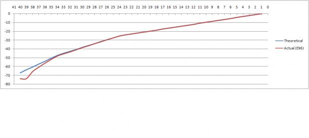
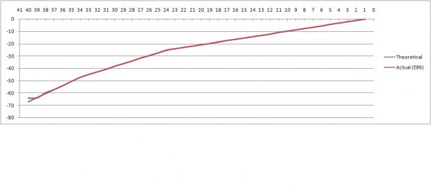
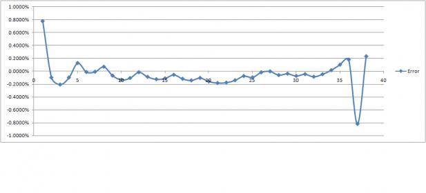
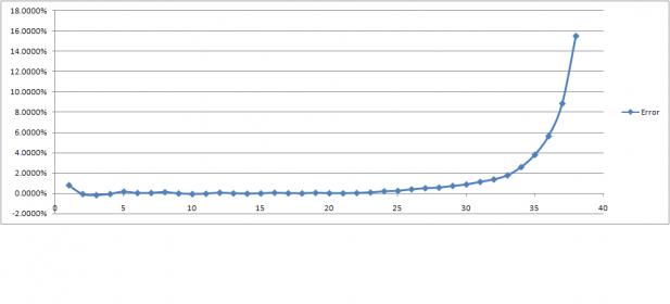
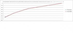
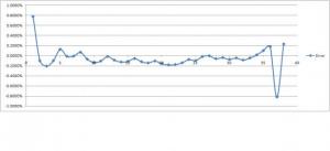
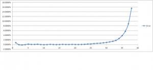
Cool! I'll try it out! The below results are using the VLOOKUP function. So, this turns out to give some unexpected results. The basic schematic is a series attenuator like this: Notice I'm using a three slope curve, not the traditional log curve. The issue is once you get to the higher attenuation steps, things go crazy. I'm still trying to figure out why. At first, I figured it was because there are course E96 values < 10 ohm in film resistor line I'm looking at. But, then I just set the values < 10 to the exact theoretical value, and Exhibit A (atten1.jpg) is the resulting graph. Notice the deviation. My other theory is somehow the error from the series resistors above somehow catches up and throws the balance off... anyways, any ideas? So, next I plotted the error between the theoretical value and the E96 values on another graph, see Exhibit B (atten2.jpg) and the non linearity at both ends of the stepper becomes obvious. Now, if you sit and play with the lower values, you can actually coerce the values a bit, but then you get this strange deal with the first 2 steps, where you have a NOOP of sort and the volume doesn't change. This is rather strange, but maybe acceptable. See atten3.jpg and atten4.jpg. Still working on some other features, then I can post the spreadsheet. A few questions in addition to comments on the above: What's the best way to provide a "mute" stop (yeah, stupid question I know)? Is there any reason I cannot use the current sensing thin film resistors for values < 10 ohm, or alternately, how hard is it to mount smaller SMD resistors on 0805 pads, if perhaps they are available < 10 ohm in smaller case sizes?

-
It was a true stepper, probably one of the best steppers out there. 40 steps. Sells for about $260 for a stereo unit these days.
-
oh, then I agree with that :)
-
just curious, does Ray normally publish internal pics? Just surprised to see that he plans to on this one...
-
I dunno about such a blanket statement like that. Seems rather presumptuous on many counts.
-
no, the one you ordered (you may have an invoice in your e-mail). let me see what I have. I know I have some, just I have no idea how many..
-
so... looks like I'm making my own spreadsheet.. So a question. Anyone know a function in Excel that is similar to VLOOKUP but doesn't have this caveat "not_exact_match determines if you are looking for an exact match based on value. Enter FALSE to find an exact match. Enter TRUE to find an approximate match, which means that if an exact match if not found, then the VLookup function will look for the next largest value that is less than value." I'd like it to return the closest value period. None of this next largest nonsense.
-
Dark forces? Hmm... it's just one a byte change...not exactly rocket science. I could volunteer to send him a patch?
-
well, one of the better attenuators I've heard was the TKD stepper with S102 shunt, championed by non other than Bob Crump.
-
Because they are the output of the CRC filters. So, the "D" goes to +V on each board and "A" goes to -V on each board and then GND goes to GND on each board. I'll double check things, but that should be correct. Steve, are you sure you don't have those other resistors? Can you check the invoice?
-
sorry, got things swapped, the above is correct.
-
meh, nevermind. I'll call the top left cap terminal "A", top right "B", bottom left "C" and bottom right "D" and all the terminals touching the copper are GND... so you need: terminal with the cutoff on the right bridge goes to "B" the terminal caddy-corner from that one goes to GND terminal with the cutoff on the left bridge goes to GND and the terminal caddy-corner from that goes to "C" next step is the following: (1) 2.2K 3W resistor from "B" to GND (it's blue colored) (1) 2.2K 3W resistor from "C" to GND (4) 0.47 ohm resistors (also blue colored) from "A" to "B" (4) 0.47 ohm resistors from "C" to "D" Let's see what ideas you have to mount the above The 0.47 ohm resistors will get warm, so whatever you do you need to make sure the bodies aren't touching each other, so they can easily dissipate heat.
-
swt61: you get an "E" for effort, but you might not want to turn things on quite yet. I'll take your pic and mark up the changes edit: can you remind me where the "notches"/"cut off corner" are on those bridges, so I can orient the connections correctly?
-
-
maybe mod you transformer boxes with these: DAYTON WRIGHT SPEAKER ELECTROSTATIC LOGAN TRANSFORMER S - eBay (item 390029326226 end time Apr-07-09 08:04:32 PDT)
-
Here are the resistor lines I'm currently considering. Any opinions on which might be the lower noise and lower distortion resistors? http://www.irctt.com/pdf_files/PFC-COM.pdf http://www.farnell.com/datasheets/3698.pdf http://www.farnell.com/datasheets/43145.pdf By the way, this statement is more or less "Due to special technology used to produce tight tolerance, low TCR at high values the RP73 resistor is not individually part marked"
-
yay! my jig shipped from front panel express, so I may send that down your way soon as well, if you don't mind. Do you happen to have 3.5mm and 4.5mm drill bits? oh, when placing the devices on the heat sink, you'll want to place them so the long side of the board is oriented along the long side of the heat sink. You can center them, or actually mount the devices an inch or two down from center. This seems to work better in my experience and thermal simulations. I cannot wait to see them mounted with stand offs and what not. Also, those orangish Bergquist pads I sent are decently hearty, but try not to torque down and untorque the devices too many times. If a tear or some other sort of rip occurs in the pads, it will be bad news ... things will burn and you'll be unhappy. So, just treat them as fragile and try not to modify things too much once they get situated. Once the devices heat up, then they will sorta melt and form to the heat sinks. You can lightly sand the semiconductors (!) and the heat sinks as well before mounting the devices. I use 600 grit sandpaper. After your done sanding, clean the area to make sure no aluminum shards are hanging around.
-
I'd recommend prototyping with the actual passive parts that are going to be provided in the kit. So, it would be helpful to have a BOM I think. I believe both you and Jacob may be working on one?