starcat
-
Posts
246 -
Joined
-
Last visited
Content Type
Profiles
Forums
Events
Everything posted by starcat
-
Using 282VA trafo (with [email protected] secondaries) divided by 230V line voltage * 133% gives me 1.63A for the fuse. As it is pretty much oversized, should opt for 1.5A or 2A fuse and should I combine it with a 1.6A (CL-130) or 1.7A (CL-120) termistor for inrush current protection, what is your take on this?
-
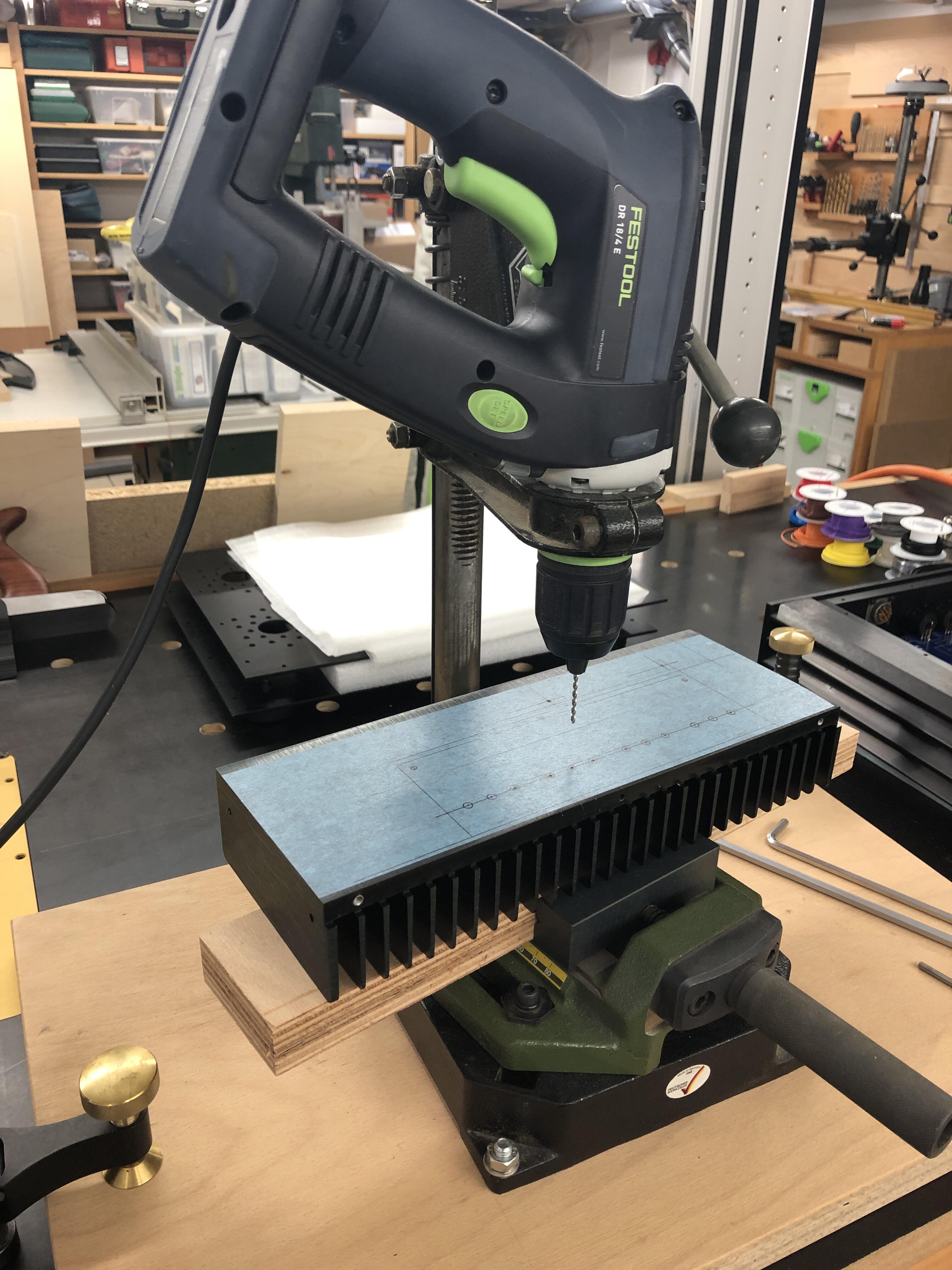
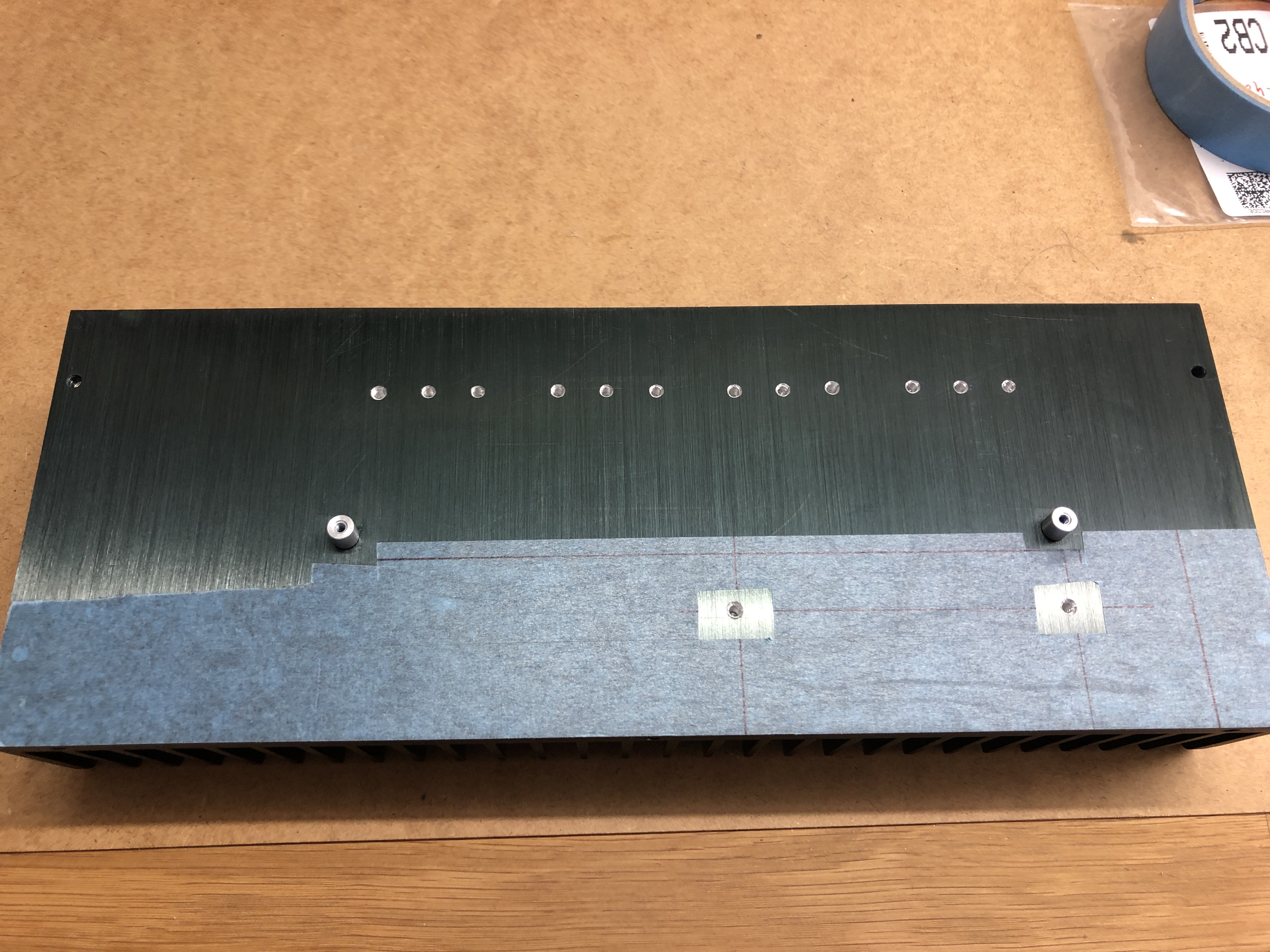
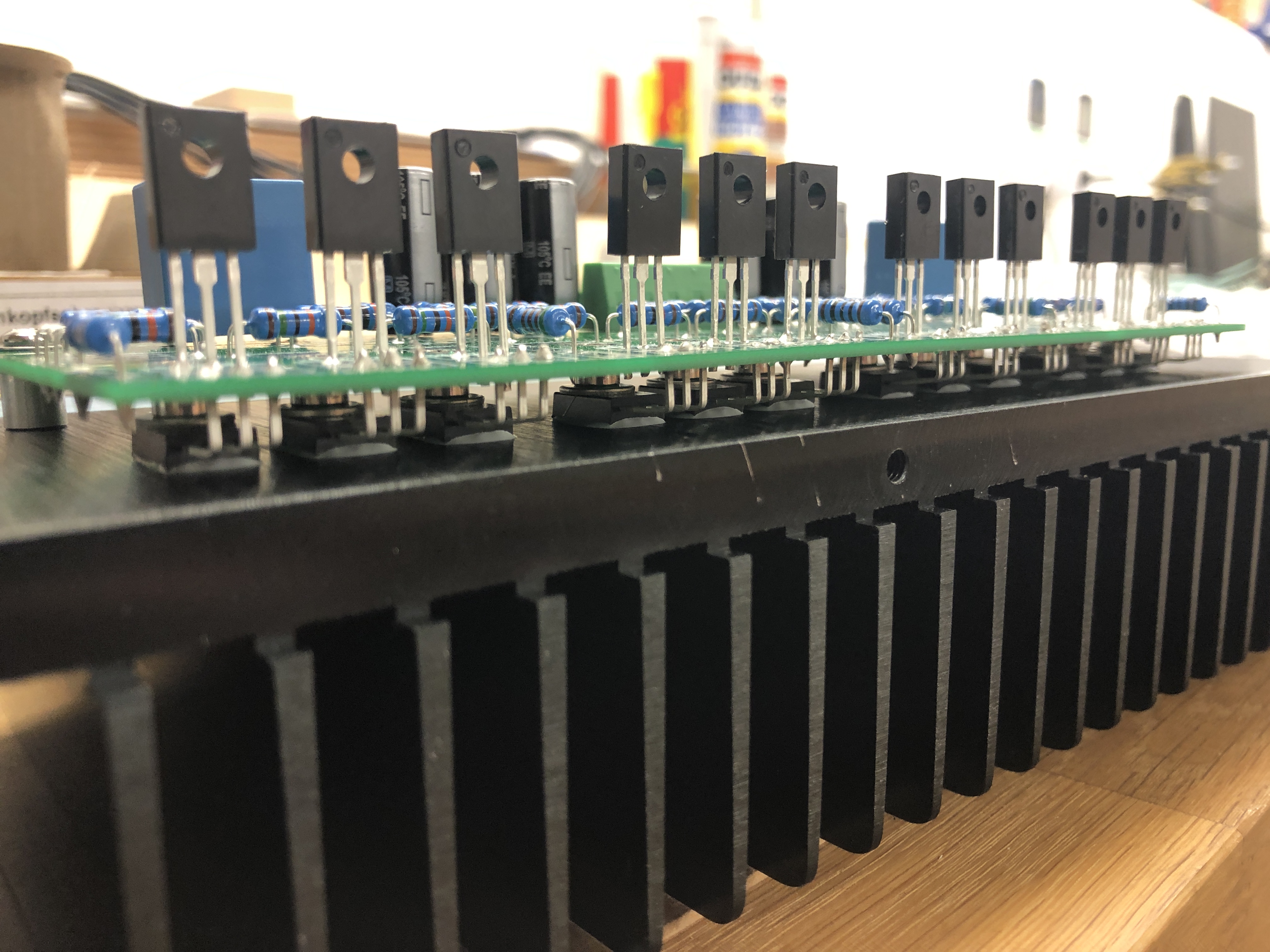
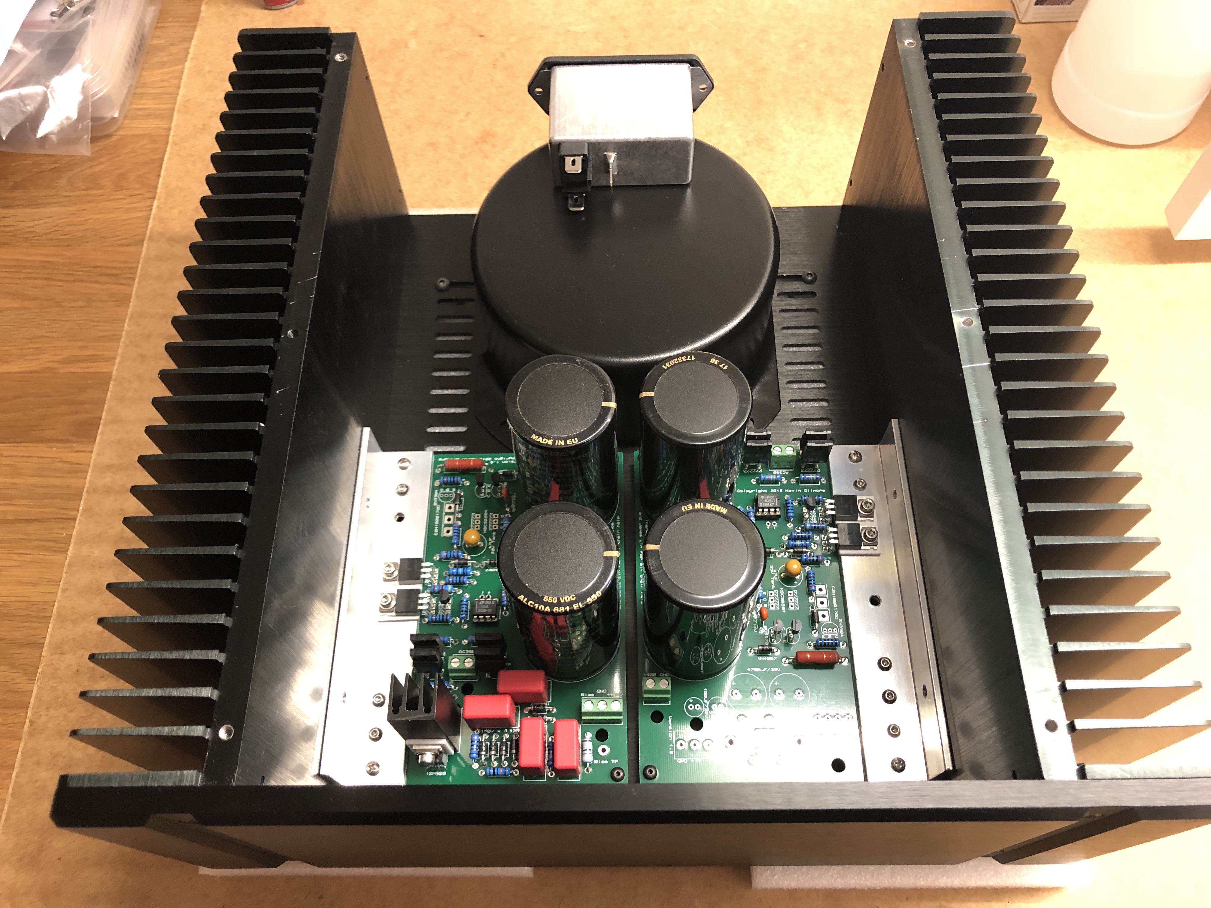
Drilling and taping holes... amp boards now mounted to the sinks.

-
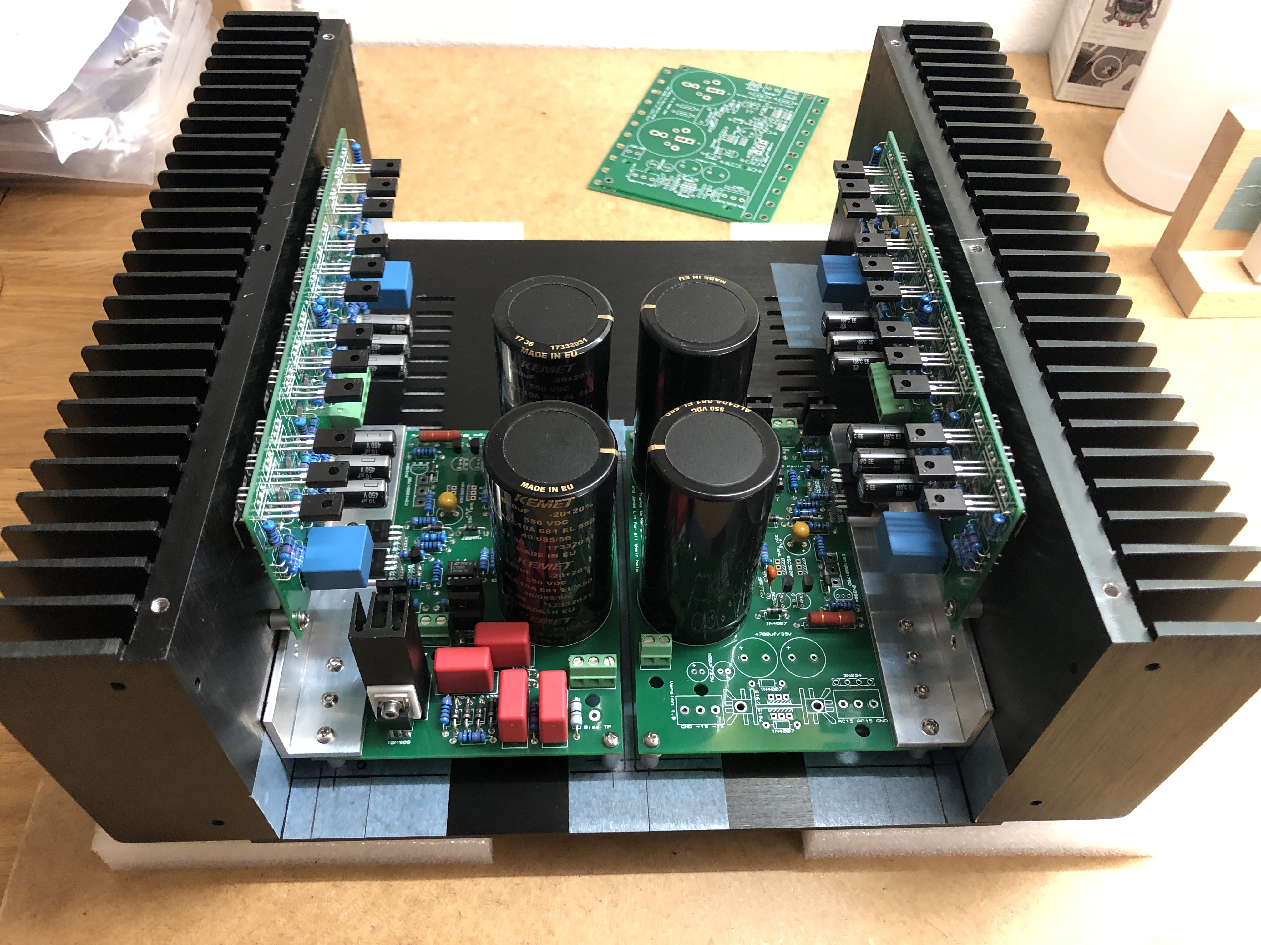
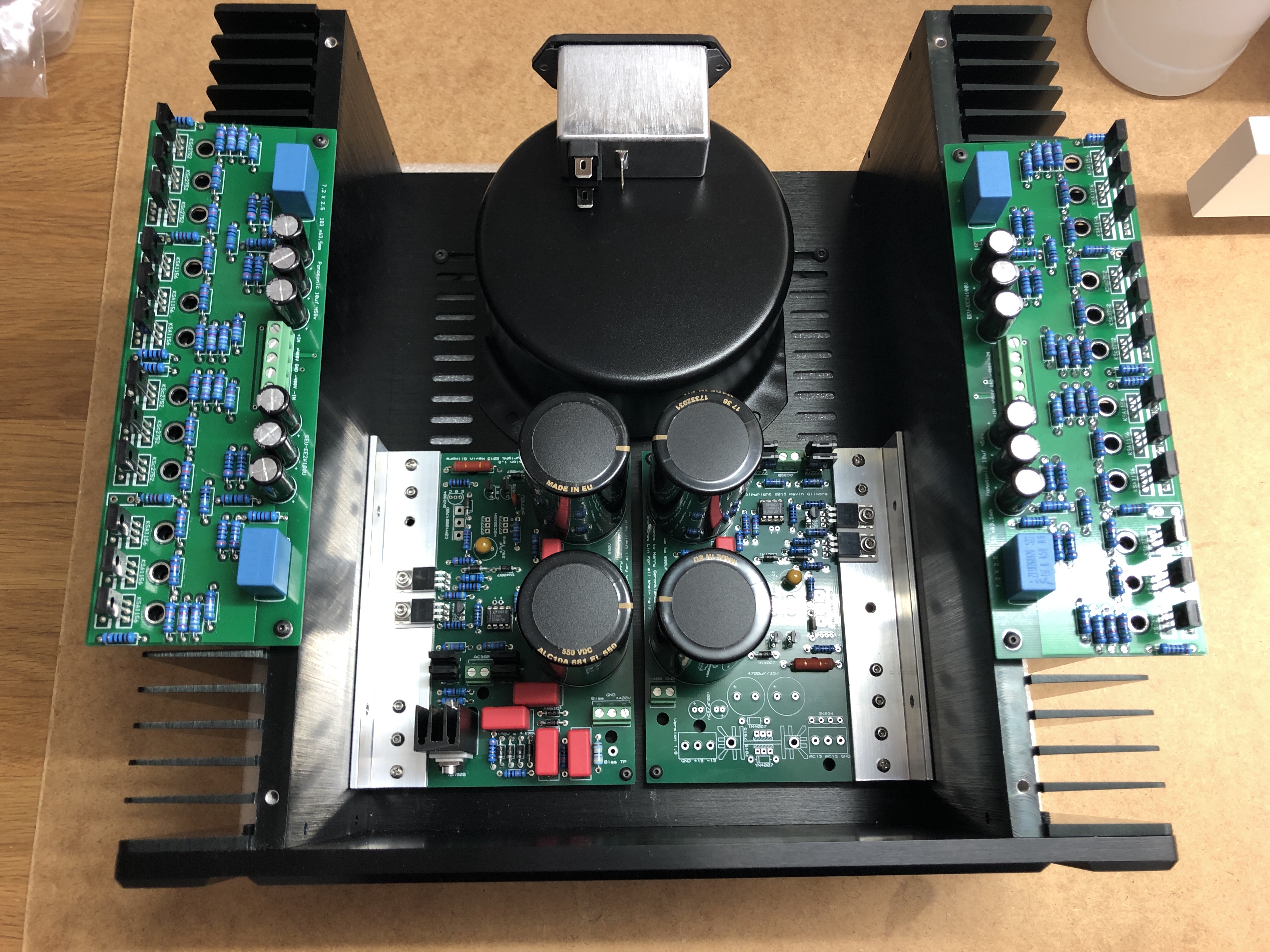
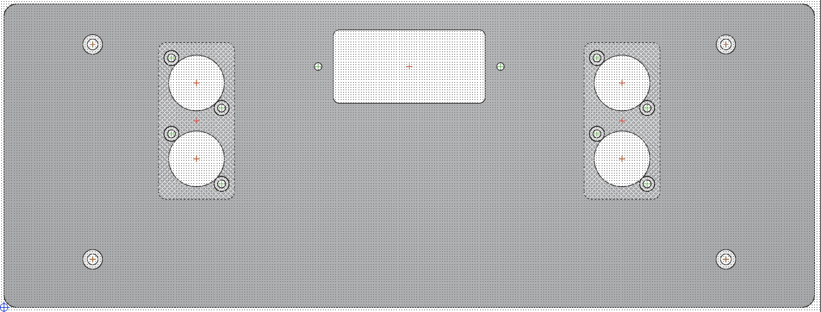
Laying down the modules for my CFAE. I decided to go with the GRHV instead of the BH Mini. Custom making the front and back panels. Back panel will have on the left/right symmetrically laid out and flush mounted the XLR ins/loop-outs and in the middle the IEC inlet. Fabricating the PCB boards for the XLR in/outs atm. Looking to use the CP4-2500 pot on a board as well together with two Stax teflon jacks on the front, symmetrically positioned left/right from the pot. Will use the 2.54mm Amphenol PV wire to board connectors between the XLR and volume pot PCBs as connectors are gold plated and directional, crimping a shielded Sommer Cable Cicada SO-D14, similar to the Canare L-2B2AT. Using 600V 300°C teflon wire for the HV. And... waiting for remaining components and transistors for the GRHV.
-
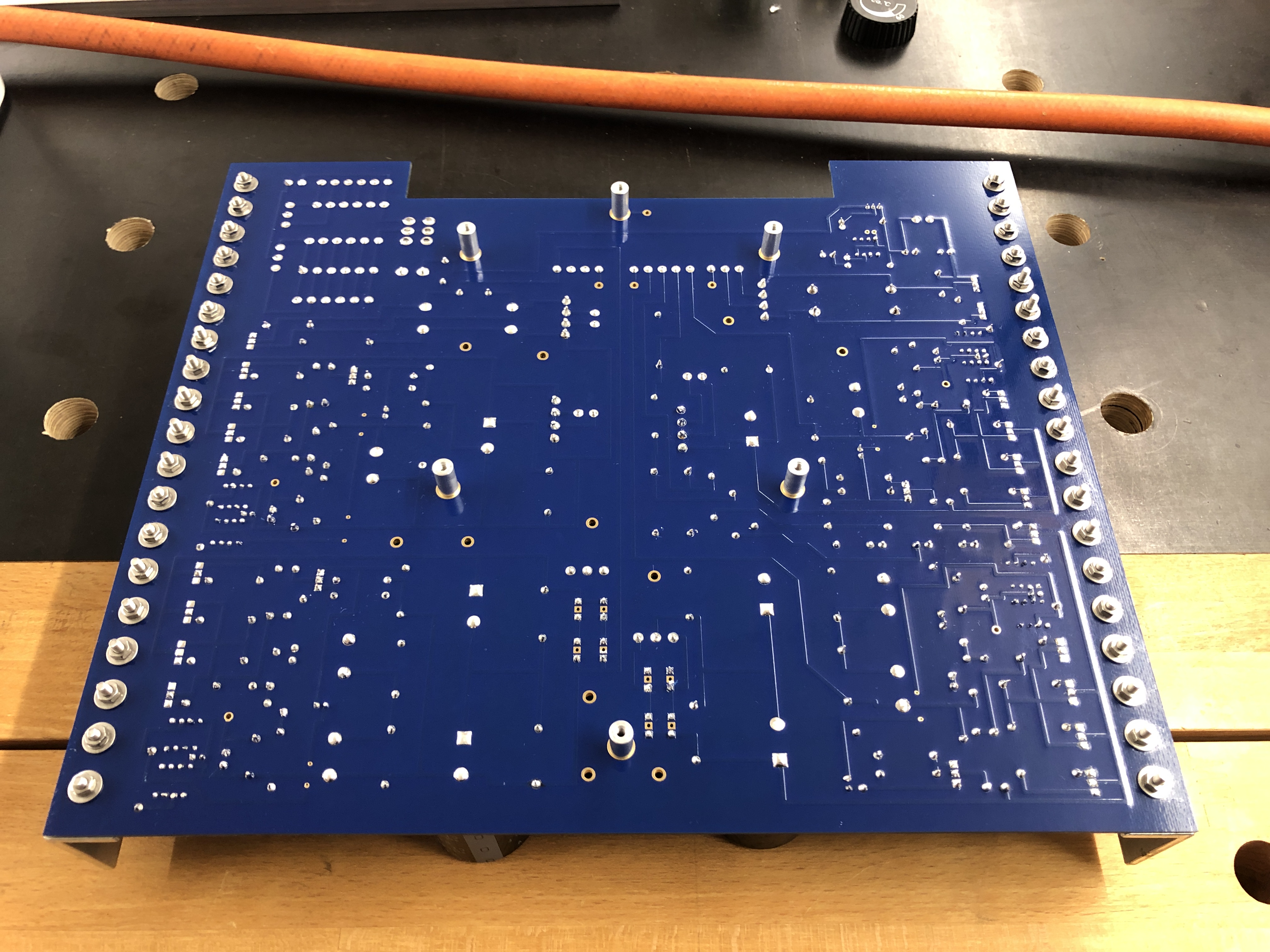
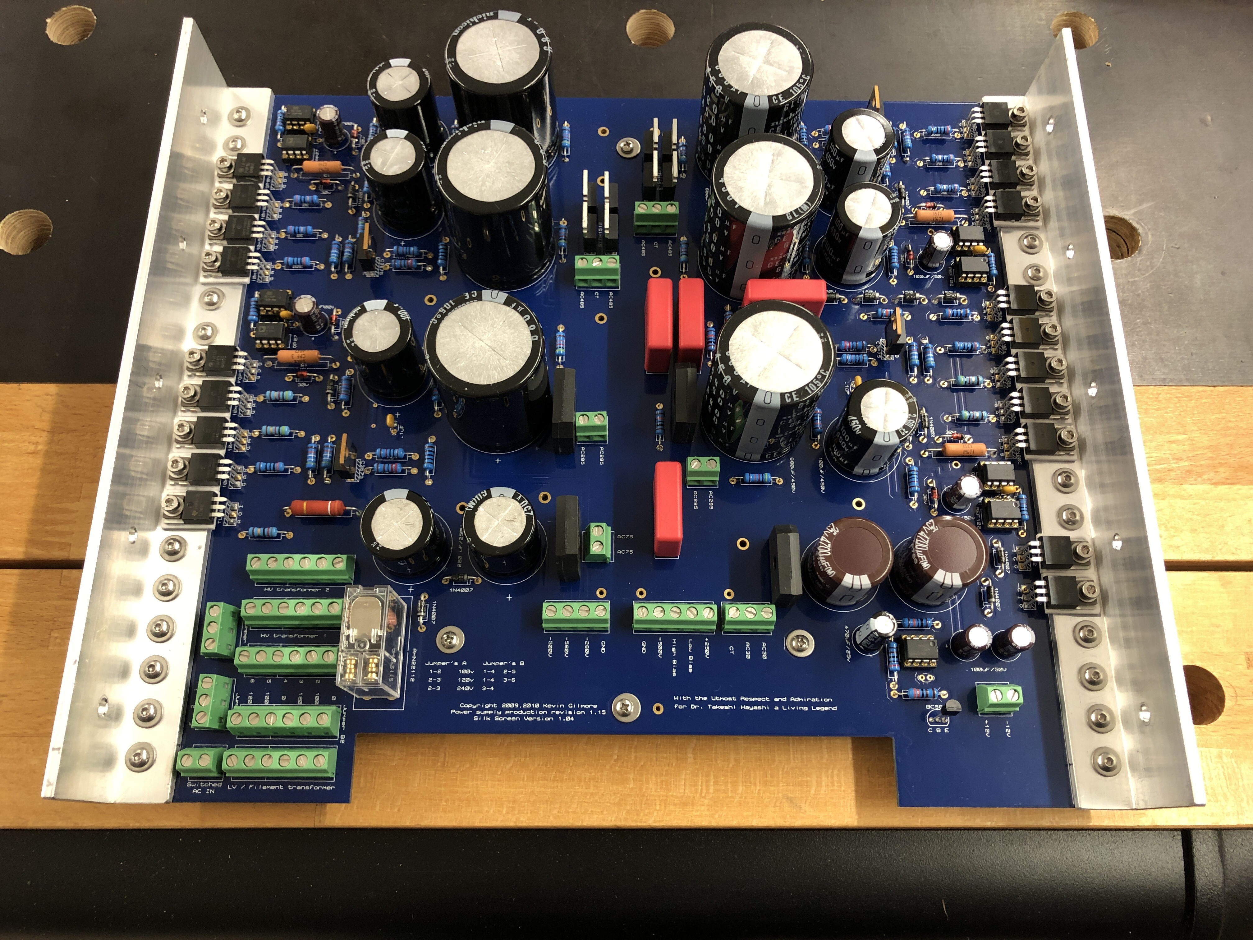
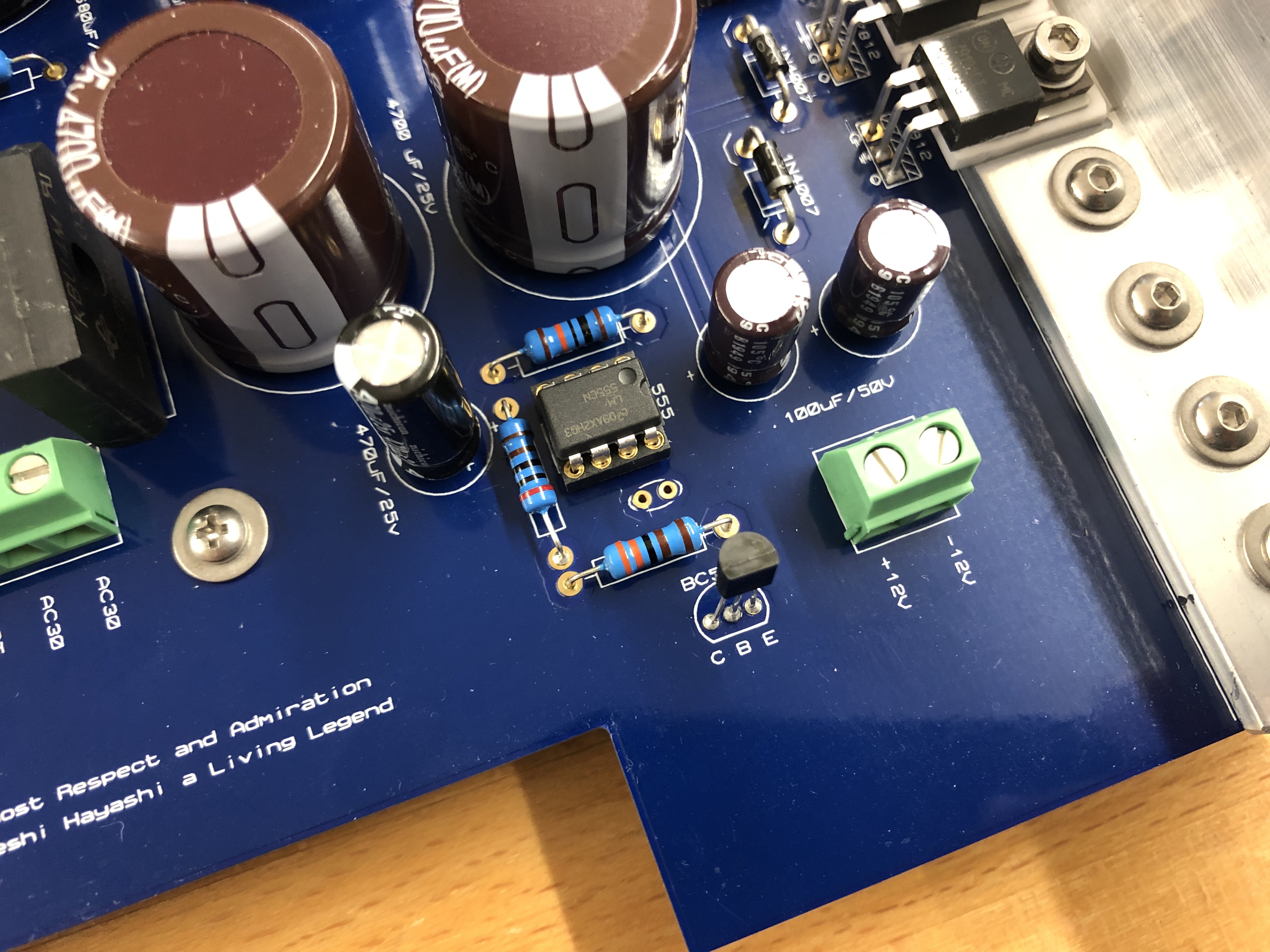
Soldered the last cs3675 and thoroughly cleaned the PSU board. And of course a single .1uF 50V is missing and Mouser again has long lead time ot it.
-
Hey Pars, the goldenreference6D.zip has two sets of outpus.
-
You can use the goldenreference6D.zip and skip yourself the further hassle. It has been checked and built numerous times and is more than good enough.
-
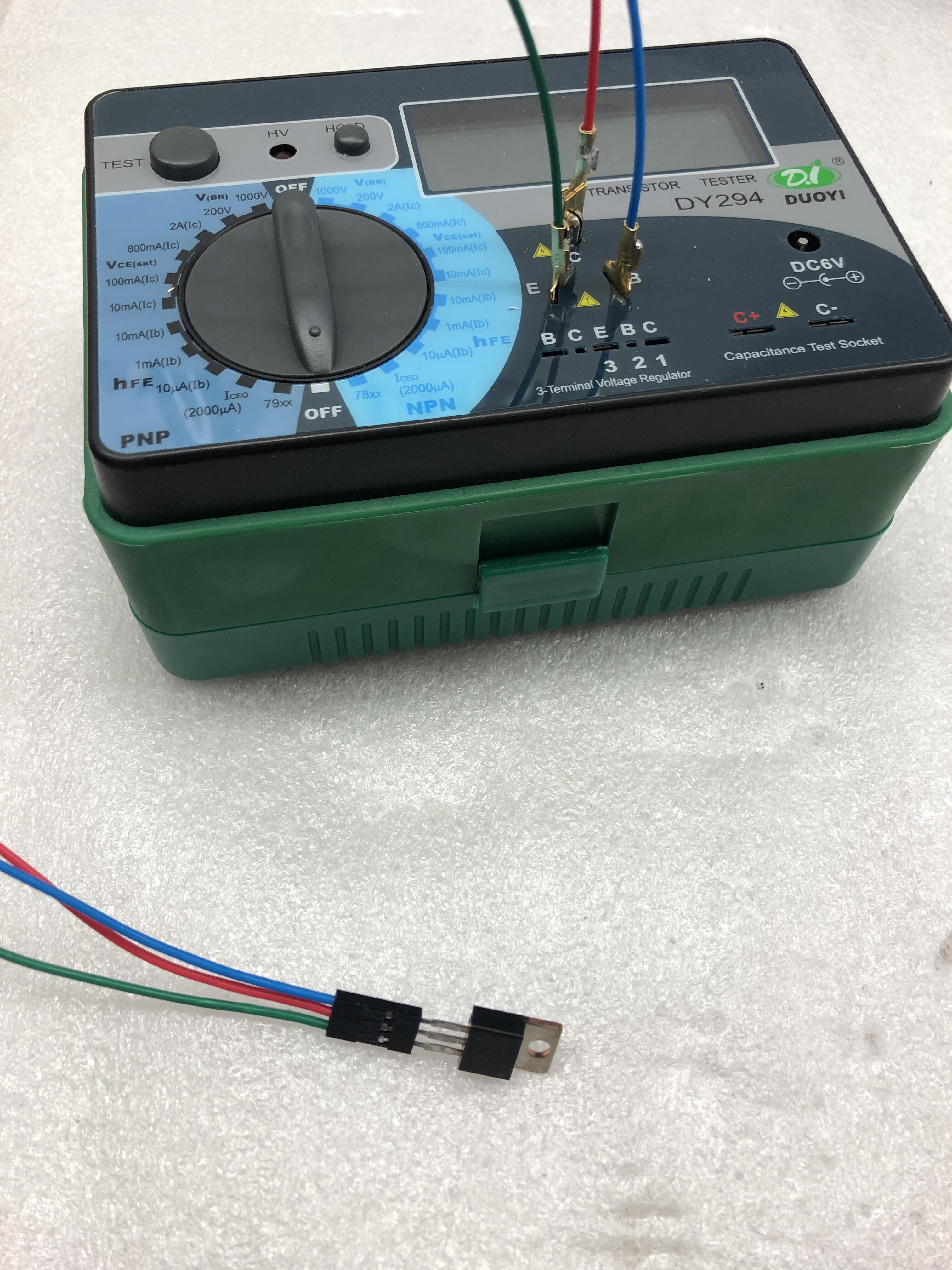
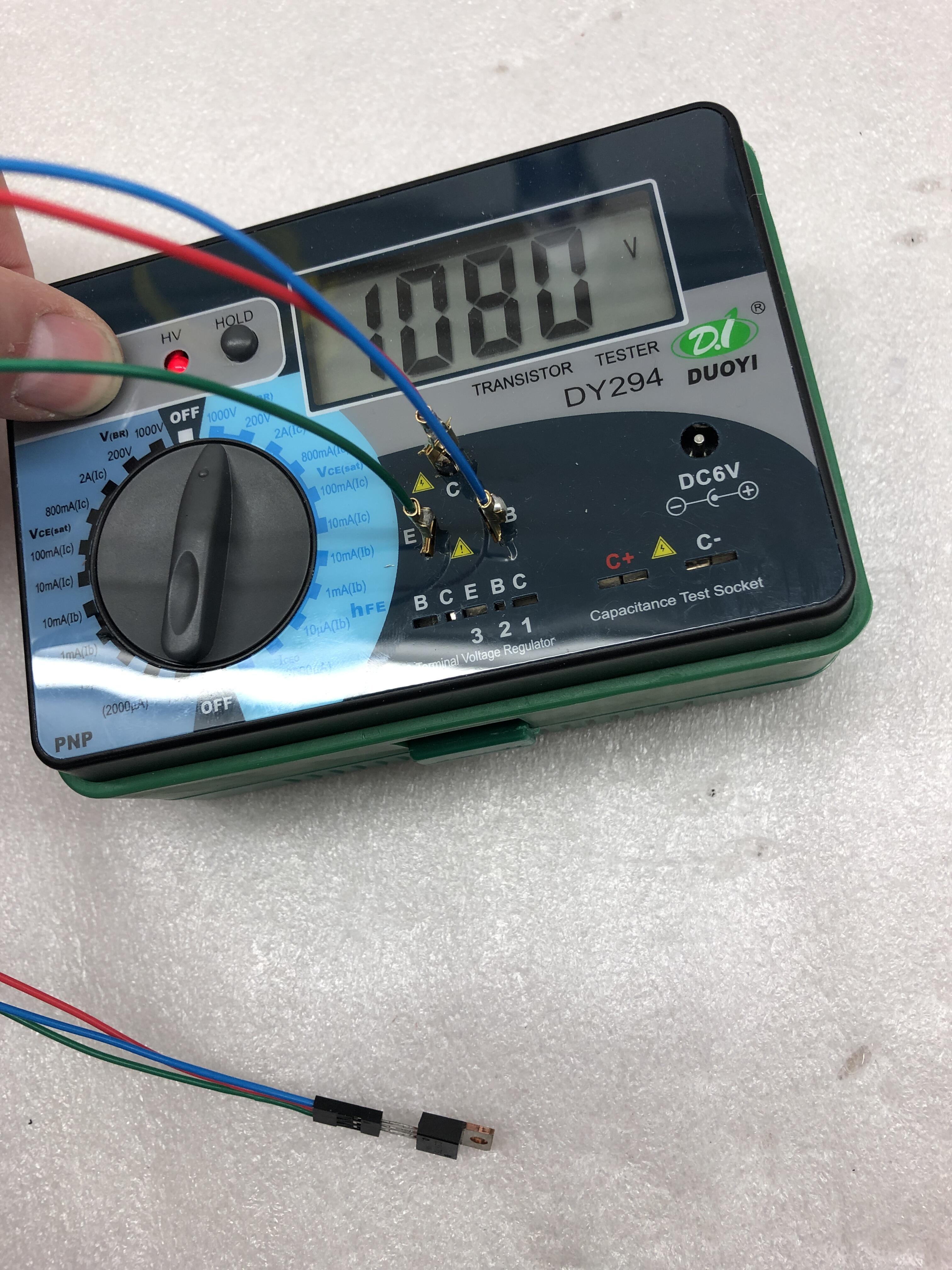
Adapter was the magic word. Made one with a 3-pin Dupont connector... very easy to swap the transistors. Thank you very much, champs! The 2cs3675 test somewhere between 1030-1120V on the DY294. Any special test procedures I should follow? Testing first with the Peak DCA75 checking pin's and type then the breakdown voltage with the DY294.
-
Thanks, James. Always impressive to see shipping cost more than the actual item: https://www.ebay.de/itm/283700277843
-
Hey JoaMat, what adapter is this, can you please share? Need to test all mine for the DIY T2.
-

and now for something completely different part 3
starcat replied to kevin gilmore's topic in Do It Yourself
Just go 2x CFA3 boards and 2x GRLV (on one or even two transformers). For the amp you do not need to separate the + and - per channel, so 2x CFA3 boards is more than good to go. No need to put the CFA3 boards in separate cases, if you want to separate the L and R channels, put an aluminium divider in the mid of the amp case and use per channel umbilical on the back (off separate GRLVs and transformers in the PSU case), so basically going strict dual mono in two chassis in total. That's already more than overkill. You can have the headphone protector as well (for dynamic headphones, stats don't need that) and eventually the ZF/SS selector (which I didn't do). -
and now for something completely different part 3
starcat replied to kevin gilmore's topic in Do It Yourself
SMD version of the CFA Electrostatic -
James, were the discoloured resistors KOA or Xicon?
-
I still have not soldered the LEDs to the mainboard, so any ideas for new P/N's are highly welcome 🙂
-
What is the white deck middle to the right, with both rotary knob, on the right to the Dartzeel pre-amp?
-
For that money one is better of connecting it to a battery. Much better and cheaper. Or if you like it modular: 1025uF 1800VDC 115A Modular DCR Check out the 600V Kemet 2100uF 10% and the 900V version for a much more realistic price.
-
900V and only 10%. 75mm high.
-
I would say electrolytic, yes. Interesting where he has got them as they aren't off the shelf.
-
Who is this guy from Vietnam? I would actually put 680uF but can't find any orderable in 550VDC...
-
Thanks Kevin for your feedback. Well, 680uF might be less dangerous, but still dangerous enough and for either precautions need to be taken. The question was if the circuit will be working properly with 1000uF as well or any side effects are to be expected if going above 680uF.
-
This is exactly what I have been fearing from. Other than that the case fits it perfectly, with just some 5-6mm or so clearance to the top plate (it is not a 2U case, so more room). Some of the smaller ALC10 series caps, Mouser is selling only in quantities of 1000x, kind of nice! @kevin gilmoreWhat would be your thought about using a 1000uF 550V cap in the GRHV? Appreciated all the feedback!
-
Thanks, James, appreciated. Going then with 550V caps. The only one however that is kind of orderable atm at Mouser is a 1000uF 550V one, the KEMET ALC10A102EP550 - possible to use this one as the board says up to 680uF... Physically it will just fit perfectly in the case.
-
Hey guys, very nice builds here!. Are the srx6rev2.zip and srxshunt3.zip for the PSU the latest gerber versions? Thanks a lot.
-
Powering the ES CFA with 400VDC from the GRHV, is there any need for 550V electrolytic caps in the GRHV or would 450V do fine as well, I mean even in the T2 the caps are 450V? PS: I am building the GRHV as well and will decide later on which PSU to leave with the amp.
-
and now for something completely different part 3
starcat replied to kevin gilmore's topic in Do It Yourself
Thanks, James, highly appreciated your feedback. -
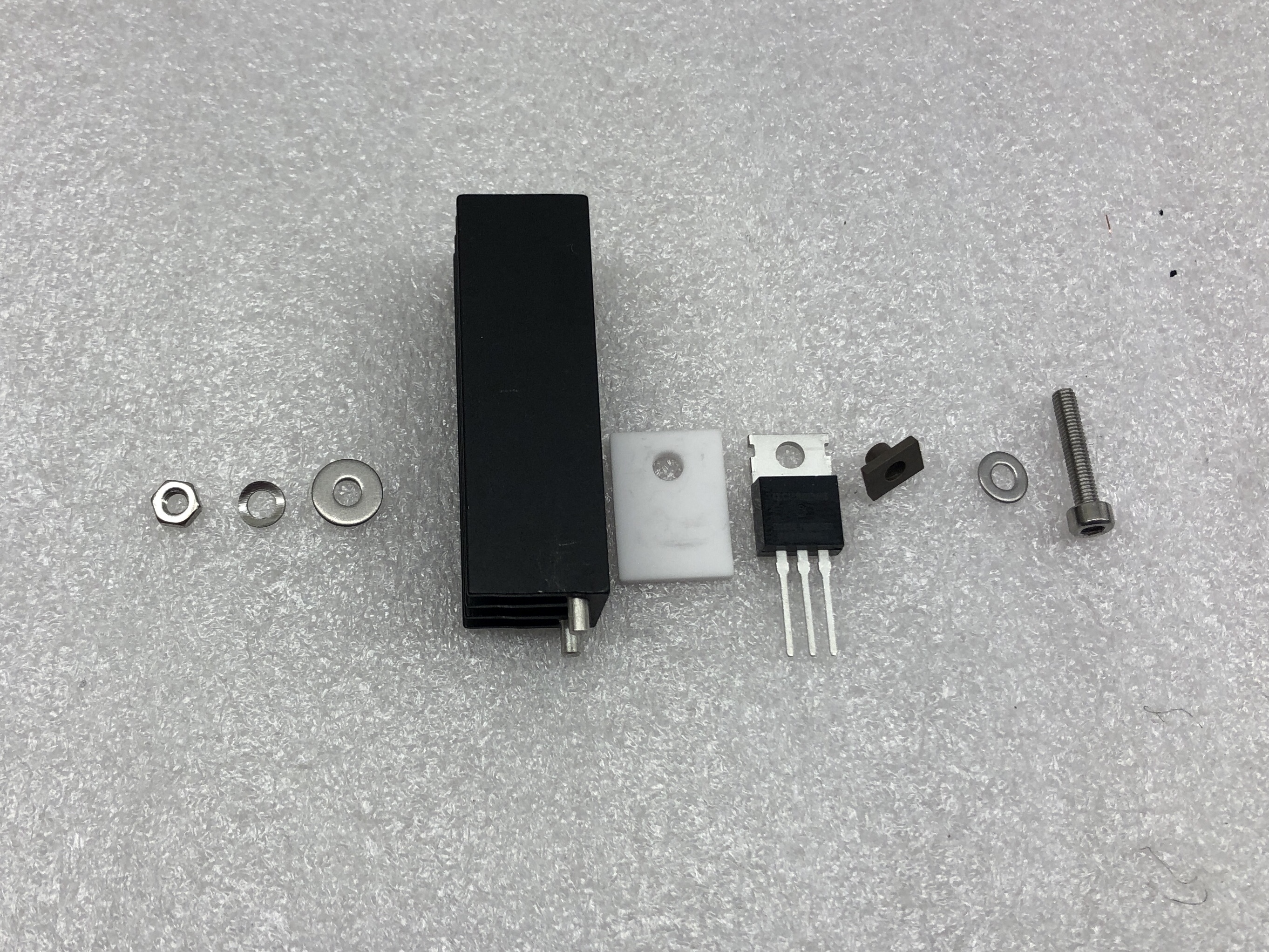
Thanks, Jose. This looks like the final setup using stainless steel hardware and non conductive EK-TIM Ectotherm thermal compound on both sides of the Aavid isolator.