dsavitsk
High Rollers
-
Joined
Everything posted by dsavitsk
-
Used to be that Apple was a hardware company that created an OS to sell the physical units. Now, Apple is actually a memory company that makes all sorts of loss leading products to sell it. One question -- anyone have any insight into running Xterm on an Android tablet? I was thinking that a *BSD music server/player with a remote interface would be just the sort of music system I have been looking for, and not finding, for years. Best I've come up with is an RDP client on a laptop to control an XP box, but it's not ideal and is way too cumbersome ... and I hate the squeezeserver, so that has ceased to be an option.
-
An orange, and a banana, and a chocolate chip cookie dipped in ganache.
-
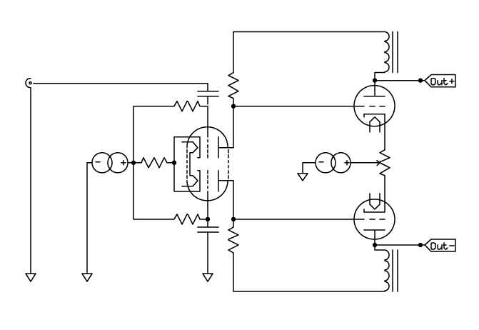
I was thinking that you were zeroing offset between the two plates, in which case R7 would need to be in a different place. But, yes, as you have it, you can zero it w/r/t/ ground, though you can't do it for both sides. But, why does that matter? The headphones appear to be differential, don't connect to ground, and thus have no zero reference? Instead, they just need to sit some voltage below the bias. So, you'd either simply increase the bias to some voltage above the plates, or you could tie the B+ to ground and consider it a negative rail only. Something like the LL1668 as a plate choke will drop ~7V in this setup, which seems pretty incidental, and will keep the offset from bias pretty close to what you want.
-
As someone who has never built a stat amp, here's my contribution Basically, LTP input and output stages. Choke loads on the output, and while chokes are not free, I think the savings of not needing a bipolar supply would make up for it.
-
I think R7 is out of place, too. Have you compared the driver + cathodyne to just using the first tube as a LTP splitter? I don't have enough experience with either topology to form much of an opinion so I am curious if you tried both. One thought, though, is that LTP front end might enable DC coupling and eliminating the negative rail (to keep the cathode load high (though, does it really matter?), use a choke, or use a single CCS bypassed by a high value resistor to give some slop)?
-
Should the grid of V4 be connected to that side of R3?
-
I have a scsi raid card and 3 scsi HDDs that are yours for the shipping if you want them. Otherwise, I'd buy a used thinkpad X61 and call it a day
-
Pffft. Real DIYers have MAPP gas torches ...
-
Some people argue that the perceived big sound of DHTs is basically reverb from the DH filaments. Any correlation between people who like the LCD2 and people who like 300b/2a3/307a/etc headphone amps?
-
I took a differential geometry class once, and I'm pretty sure it was all made up as the professor went along. all the way with gauss bonnet
-
That sounds like no fun at all. Best wishes for a speedy recovery.
-
No, not dead, just delayed. We have, in hand, what we hope to be the final revision of the PCB -- it is now 14" long. We are waiting on a prototype of the final case, which we thought would have arrived already. Probably in the next week -- other cases ordered at the same time from the same vendor are in transit, so this one can't be far behind. There were only two of the final prototype boards made. Tom is building one, but if anyone (HiGHFLYiN9) wants to do the other, I also have a set of the transformers and a blank 14" case. Whomever wants it can have it for cost.
-
Thanks Marc -- I'd appreciate it.
-
Thanks everyone! I spent most of my birthday driving from Ithaca to Chicago. Didnt quite make it, so I am spending the rest in a dumpy hotel in fremont Indiana home tomorrow ...
-
Maybe they mean Australian winter
-
Does anyone have a 1uF, 250V or higher electrolytic cap (on 2.5mm pins)?
-
I don't get the appeal -- I don't listen to headphones because I can't afford speakers, I listen to them because I like them better. Why would I want to ruin that experience?
-
There is this weird belief at HF that a 10W amp is really different from a 1W amp when putting out 1/10W. I heard a pair of these at the NYC meet, and they sounded like PA speakers in a gym. All resonance and awful. Maybe the felt had fallen out, or maybe the amp was a bad match, or maybe I was just not in the mood, but it was not good. Very odd. I am itching to hear another pair now that are known good on a system I am familiar with as something definitely felt wrong.
-
The auditory neuroscience community uses Etymotic, if that means anything.
-
The Wolfson WM8741 DAC chips have a voltage output of 2Vrms with a full scale digital signal. 2Vrms is about 5.7Vp-p. The DAC chips can only handle a PS of up to 5.5V, and are really recommended to run at 5V (actually, they can take 7V, but Wolfson will tell you never to actually run them over 5.5V). Anyhow, suffice it to say that the chips clip. They have an option to cut the signal by 2dB which results in 4.5Vp-p (~1.59Vrms) which they do just fine with. Different headphones perform differently with different amplifiers. Full stop. The notion that one perfect amp can perfectly drive everything is simply nonsense. For instance, with a traditional voltage amplifier, I think Grados do best with 10-15 ohms of Zout, balanced or SE. With an amp with near 0 Zout, they sound terrible. And this is a large part of the reason for the "Grados work well with tubes" myth in that tube amps tend to have a non-0 Zout. However, I also think they really shine with a Gm amp with a Zout in the hundreds, if not thousands, of ohms. Those same amps may not do well on other brands/designs. So, finding just the right synergistic combo would be a lot easier if we started matching gear in reasonable ways, rather than treating every headphone as a black box to be driven the same as every other one. Nobody expects a 45 amp to drive their B&W 801's, and nobody expects their Krell monstrosity to drive Loethers, so why do we expect this in the headphone world? Anyhow, this is a great thread so far
-
I could use one of his his XO's @ 24.576
-
Basically, the only step left is telling the case manufacturer to go ahead and start. That should happen this week ... I think.
-
Good to hear you solved this. And, good to know that we need to check each of these transformers individually before sending them out.
-
Too many hand matched parts/different configurations to make that work. Also, I am concerned that stencils and/or ovens will leave filled through holes. So, the directional hot air seems like a decent solution. Pace is definitely too expensive, but I think I'll give one of the less expensive ones a try and see what happens. I took rework to suggest that nobody would solder a whole PCB full of SMD parts with one, but that it was the best way to do a few. I guess I'll find out.
-
Happy Birthday!