-
Posts
4,906 -
Joined
-
Days Won
79
Content Type
Profiles
Forums
Events
Everything posted by dsavitsk
-
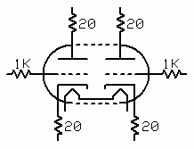
sure -- use carbon comps. Either vintage from AES or Ohmite Little Demons from Digikey. replace the first 1K5 resistor with something like a hammond 154G err, well, there is an issue which is that the Z out of the preamp is like 50K and won't likely do a good job driving the transformer's inductance. I think you should either work another tube in there (6T4 perhaps?) to lower the Z out so it can actually drive something like a cable, or the next stage, or you should switch from the 12ax7 to something with a lower rp -- maybe a 12ay7 or 12at7. The former will increase the signal a bit -- more than the 6db you were looking for, while the latter will lower it. You'll need to make some other changes to do the latter, however. Oh, and a 0.1u coupling cap will be too small in either case But, assuming you do lower the impedance, on the primary you would connect out to + and - to ground (or the cathode if you like), and leave the input ct unconnected. For out, the "right" way to do it is to connect the + and - transformer taps to hot and cold, and connect the chassis (now grounded to safety ground) to the "ground" pin on the xlr.
-
Tubes and caps are the most likely. It is possible that resistors have drifted, but it is doubtful they have drifted that much. Really, I'd guess you are just used to the sound and that it is not as good as you once thought Or, maybe your pickups are dying a slow death. But, the schematic is too small to see clearly. If you want to quiet the noise, replace one of the resistors in the PS with a cheap choke -- it'll do wonders. particularly since you plug an instrument that you touch in to this, that should be fixed asap. You have a misunderstanding of what "balanced" means. All those amps and cd players that give you an extra 6db when balanced do so because they are really bridged which doubles the circuit. If you want 6 db more from this, buy another one and use them both at the same time. If you want a balanced output, use an output transformer -- Edcor would be good here, something like the XSM10K/10K would likely work well and could just be bolted to the output. The best guitar amp forum I know is http://www.ax84.com/ Diyaudio tube section is also pretty good.
-
I'd spend $60 on a couple of transistor, a few capacitors, a 9V battery, and a plastic box, and build something super cheap that will embarrass the other stuff in this thread. You only have one source, after all, so the switch and extra RCA jacks are superfluous.
-

Wavelength WaveLink Asynchronous USB to S/PDIF converter.
dsavitsk replied to Hopstretch's topic in Home Source Components
It's very clever how they put the PCB upside down, so they can show an "internal" picture without actually showing anything -
-
One thing -- these are high Gm tubes, and they can and will oscillate without some care. And, the long leads necessary to build an adapter can act as antennae. To that end, stoppers on all the pins (of the 9 pin socket), except the heaters, would be prudent. I'd maybe put 1K resistors on the grid pins, and 10 to 20 ohm resistors on the cathode and plate pins. The best resistors to use would be SMDs, but if that presents too much of a soldering challenge, some sort of carbon film or comps would be fine. Just get them as close to the tube pins as possible. Also, keep in mind that oscillation is not necessarilly obvious -- sometimes it will just manifest itself as a bit of hardness, or glare, or jut lack of midrange clarity. Indeed, ECC99's have a reputation of being hard sounding, and I wouldn't be at all surprised if it isn't just a tendency to oscillate at HF. -d
-
That was my understanding, too.
-
Hi Miguel, For a given bias and current, the ecc99 runs at a higher plate voltage than the 5687 -- typically ~20% higher I'd say. This means that with a fixed plate voltage, the bias and current will run lower than on the 5687. Not knowing the circuit, I have no idea if this makes any difference, but probably not. However, 5687's are linear, plentiful, and relatively cheap, so I don't think you are gaining anything by using the other tube. I agree with Marc that I'd leave it as is and save your pennies.
-
He is Ron Buffington, he runs Liquid HiFi, and he wants to sell you the new PS Audio Perfect Wave system AND Esoteric SA-50, apparently in November.
-
Corporate Donuts Suck.
-
The USB EMU needs ASIO for digital out, but RMAA, last I checked, does not support ASIO, meaning that if you want to use RMAA to test digital sources, the EMU card won't work. This may or may not matter to you.
-
-
"I Turned Into a Martian" by the Misfits and "Jam On It" by Newcleus
-
So far as I know, the shield is not connected to anything else. But, you can just AC couple it to ground or earth or whatever. If I understand what you are saying, then no. You would have one side of the heater tied to 60V and the other, or the center, tied to ground, which would mean 60V across the heater. You'd have a race to see whether the heater or the resistors would burn up first. I think you are fine, AC or DC. Are you really getting noise from the heaters that requires all this effort to eliminate?
-

Mysteriously Musical Amplifier (Moth 300B "Problem")
dsavitsk replied to Voltron's topic in Headphone Amplification
It can be quite loud. Hook up resistors across the speaker terminals and turn your amps up to see what happens. -

Mysteriously Musical Amplifier (Moth 300B "Problem")
dsavitsk replied to Voltron's topic in Headphone Amplification
It is probably the OPTs. They do this, though it is usually inaudible over speakers. It is similar to a power transformer humming from 60Hz AC. This is a good way to destroy your OPTs. Don't do it. -
Compactron - Wikipedia, the free encyclopedia I would doubt you'll find many testers that test these. They weren't made for very long, so testers would need to be from the same era. They were basically a way to cram a bunch of tubes into one to take up a little less space. I've never seen a commercial amp that uses these. They are good for DIY since they are super cheap, but they are otherwise nothing special. At any rate, with a couple of clip leads, a multimeter, and a bench power supply, you can measure everything a tube tester can -- in fact more, and more accurately.
-
When you see that a manufacturer specs a certain amount of distortion, this is typically total harmonic distortion, the aggregation of several harmonic components, at a particular frequency. However, while THD doesn't show it, different components influence the sound differently. 10% 2nd harmonic distortion will be barely noticed, while 0.1% 17th will sound horrible. Additionally, while distortion might be one thing at one frequency, it can be totally different at another. So, what I am saying is that two different DACs that both measure "flat" and that both have similar THD specs might not actually be very similar at all. Here's a good article that covers this, and some other stuff: http://passlabs.com/pdf/articles/distortion_and_feedback.pdf
-
It doesn't sound like an EQ issue to me. It sounds like a particular distortion characteristic.
-
This is, to my ear, what NOS dac's based on the AD1865N-K sound like. See if you can borrow somebody's AudioNote to play with -- I think you'll like it.
-
My wife has written/worked on software to do this. She uses it to compare sound waves against brainwaves generated from listening to said sounds. I'll find out what format she needs the waves to be in to do the comparison. http://www.soc.northwestern.edu/brainvolts/documents/Lee_et_al_JofNeuro2009.pdf
-
Many years ago ... well, about 7 years ago, I had a Pentium 1, 150, running FreeBSD and acting as a headless music player. I basically wrote (in Python) a socket server that would serve up some basic HTML to give me a list of tracks and that would control mpg123 when I clicked one of them. I think it also had a crude queue for track lists. All in all, it was about 100 lines of code, and actually worked reasonably well. The point is that mpg123 might do what you need.
-
Actually the LL1674. Similar transformer (Kevin at K&K says they are virtually sonically indistinguishable) but on a larger core than can handle higher dBu. I think if you look around that Lynn Olson did some measurements on it, or maybe the LL1676.


