dsavitsk
High Rollers
-
Joined
Everything posted by dsavitsk
-
What is the source?
-
I am looking for measurements of the voltage out level of various sources, commercial and otherwise. Nominally, sources are "line level", but this turns out to be a term without a lot of real adherence. Consumer gear is said to be at -10dBV, which equates with ~0.316V RMS, but most sources seem to run hotter than that. Pro gear has a US standard (+4dBu or ~1.228V RMS which is 1.78dBV) and a German one (+6dBu, 1.55V RMS or 3.78dBV). Notice that V RMS, dBV, dBu, and dB are all different things -- you can convert between some of them at dB dBu dBFS dBV to volts conversion - calculator volt volts to dBu and dBV dB mW - convert dB volt convertor converter calculation online attenuation loss gain ratio reference audio engineering dBFS dBVU 0 dB audio logarithm level converter peak to p So, in order to determine what level stuff actually outputs, it is pretty simple to just measure. To do that, you will need a 60Hz 0dB test tone, and a $5 multimeter. A test tone can be downloaded from Free download of bass test tones -- there are several available, but it is probably a good idea to standardize on one. Basically, all you do is play the tone and measure the AC voltage on the meter. For balanced outputs, measure from pin 2 to 3. For single ended, from the pin to ground. You use a 60Hz tone because multimeters are designed to measure AC at the wall, which is 60Hz, so they tend to be reasonably accurate here. Some will work fine at other frequencies, but some probably won't. To get the ball rolling, my WM8741 dac (http://www.head-case.org/forums/do-yourself/476-diy-amp-such-build-gallery-153.html#post331335) that takes the output directly from the chip is ~1.96V (balanced signal) or a little over 8dBu. My other DACs run a little cooler -- for instance, my AD1865N-K based dac which uses a passive IV into C3g's that are parafeeded (parafed?) into Magnequest 15K:500 OPTs runs at ~1.32V, or ~4.6dBu. Measurements of commercial cd players and dac's would be appreciated. For extra credit, it would be interesting to measure the voltage out of listening level across headphones, but that might be another thread. It is best to do this with the phones attached. Thanks!
-
I think I disagree -- the CCS load is good as it is a high impedance load that keeps the signal current away from ground. An LED is a low impedance load that shunts AC to ground, exactly the opposite of what you want. I'd just stick with a resistor. A negative supply to tie it to would be helpful. If you are feeling really ambitious, use the choke in the cathode. Otherwise, use a CCS in the cathode and a shunting element as a voltage regulator (with a cap from B+ to the cathodes). And, I am not sure I'd run a 6c45 as high as 30mA. 20mA has worked better for me.
-
I think that's right -- IIRC, the Neko uses dual mono 1794's and a Wolfson receiver.
-
So long as you are under 8oz, Digikey shipping via first class mail nearly always gets to me in Chicago in 2 days, and costs under $2.
-
It's actually not Hammond's doing, as much as I'd like to blame them. The board fits in the case just fine, but the person who did the layout had the pot extend a tiny bit too far. Now, the intention was that the board would be just shorter than the case to allow for some wiggle, in which case things would be fine, but since the board and case are matched, a couple of washers will be needed. As Tom says, this will be fixed in the final.
-
It's the impedance selector. The on-off switch is built in to the IEC, as is the fuse. This is for safety reasons so that the fuse can't be easily defeated, and when the switch is turned off, there is nothing past the IEC that is live. Also, the yellow caps block the high voltages, so the the front 4" of the amp is entirely low voltage.
-
Good point -- for now, I think we are going to have to add a tiny shim inside the front bezel.
-
NOS, but plentiful.
-
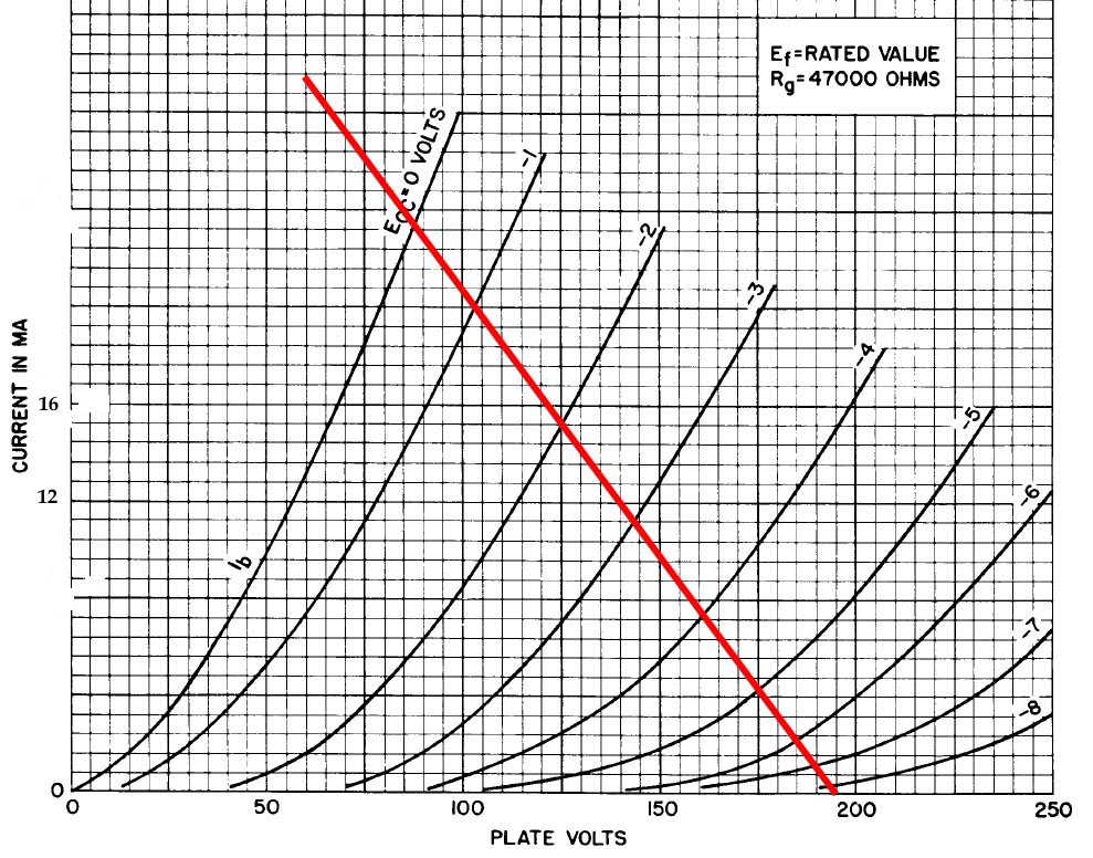
Here are the curves of the secret tube ... We use a custom made transformer with 300 and 32 ohm taps on the secondary. Without accounting for copper losses, etc, this gives an overall gain of just under 2 into 32 ohms, and just under 6 into 300 ohm loads. In reality, this probably turns into 1.5x and 4x, or something like that. But, I've been using an old TDA1545 DAC with very low output, and there is plenty of gain for that, but with a dac with normal output, there is still enough play in the pot.
-
To be even more exact, it is 0.5mm shorter than it needs to be No, just PCB mount -- you could probably socket them if you really wanted, but I'm not sure the benefit ... That's the idea -- the parts cost is remarkably low -- $1 tube, which is still a secret for now , $9 OPT. The most expensive things there are the IEC and the Alps pot (unless you use Auricaps, I suppose). I need to shoot Gary an email to be sure that it isn't going to step on any toes.
-
A little teaser ...
-
I am looking for rubber standoffs for mounting vibration sensitive parts. I have an old HDD cooler from Zalman that came with some that have a male end and a female end that are held together by pliable rubber. Anyone ever seen anything else like them?
-
Two things to think about. With all the secondaries in parallel, the copper impedance is a little more than 4 ohms. No big deal. When you step up to the next level, the copper impedance is about 16 ohms. You will, in theory, be jumping up 6db, but if you run it into 32 ohm phones, ~3db of that will be lost due to the copper so the gain will not be as big as you think. This is less of an issue with high Z phones, but it exists there, too. Second, keep in mind that the tubes only see 1/4 of the primary impedance in a push pull amp. 18:1 is ~10K:32 which is like loading the tube with 2K5. Since rp is ~1K5, this means that Zout is likely higher than you might think -- especially when you all in the 4 ohms from the copper. This is not necessarily a bad thing -- as I've said elsewhere, I think it can actually be a useful thing, but it is worth being aware of as, if nothing else, you'll lose some more gain there, too. The TCJ PushPull Calculator might prove helpful. It isn't spectacular, but it is definitely worth the $30 as it will help you get things right faster than trial and error. If I were doing it, I think I'd use a quad of 6C45's instead for the extra gain and lower rp. Or, I'd use some step up's (LL1674) on the input.
-
Why would it be a waste of time? Kevin Carter does this all the time or headphone use.
-
Is there a practical reason for the group of mounting holes to be north of center? If you added a touch of height to the FP, they could be centered which would look a little nicer to my eye. Will CE take FPE files? Otherwise, what format do they want? Yes, but will CE send you a chocolate front panel for Xmas? [ATTACH=CONFIG]2482[/ATTACH]

-
I've been using the Schurter DD11 and DD21 (for PCB mounting) lately. I can't say they are any better than anything else, but they are what I standardized on. The one problem with them is that the fuse drawers are sold separately. This is not inherently a problem, but it always seems that only Mouser will have the IEC while only Digikey will have the fuse drawer, or vice versa. I've never managed to get both from the same vendor. Note that these don't have a filter in them -- if I want a filter, I'll usually do it separately. http://www.schurterinc.com/pdf/english/typ_DD11.pdf
-
I can't offer much on the particulars. But, I can say that from a safety perspective, I really like the IECs with a built in fuse and switch. It is all I use anymore. 2 less things to worry about. And, I'd think you want the voltage selection to be a little user unfriendly -- it is not the sort of thing that should need to be changed more than once, maybe twice, over the life of an amp. Probably better it not be changed accidentally.
-
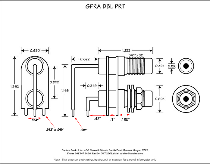
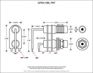
Here are some numbers from Cardas
-
Those would be fine -- a little more expensive, but not enough to break the bank. I did, and they said they don't have a better drawing, though they were able to provide a few more numbers. And, I shouldn't say it as I know how these things get abused, but they are sending me a sample to measure.
-
No, I wouldn't either -- some of your numbers don't add up. The width of the whole thing is listed as 0.63", but you have the pins that are within this being 0.81" apart. Same with the distance between the L and R signal pins -- you have 0.7", but it must be at most less than 0.622", and if the original drawing is to be believed, it should be exactly 0.273". Are these off by some multiplier perhaps?
-
Thanks, Nate!
-
I need pin diameters, spacing between those ground pins, and space from pin to panel, and probably vertical distance from board to drill centers. If you can measure some of that, that would be very appreciated. Thanks
-
Does anyone have measured dimensions for the Cardas GRFA DBL RCA jacks? I am trying to do a PCB and case layout, and Cardas doesn't give quite enough information away to actually accomplish this. Even better, anyone have an Eagle part library for these? Drawings for an alternative part from another manufacturer (Vampire?) that is of decent quality would be fine, too.
-
This is the issue with these comparisons -- the PS Audio is a decently designed and built piece of equipment made by engineers who have some idea of what they are doing. The Monica is a piece of garbage designed by someone who does not. Instead, compare a good oversampling dac to something like the Abbingdon or even an AudioNote for a more fair comparison. My experience, using both NOS and OS dacs with the same IV and analog stages is that they are closer than they are different. Most of the overly warm detail lacking that people associate with NOS has more to do with the output stages, or the cheap tda1543's typically used than anything else. Personally, I like a differential pair of AD1865N-K's run NOS more than a PCM1794 that is oversampling. But, both are fine. And, for the record, I like the TDA1543 -- It's fun to tinker around with: http://gilmore2.chem.northwestern.edu/ubb/showpage.php?fnum=3&tid=7740 Oddly enough, yes. Almost all NOS DACs are based around the TDA1543, TDA1545, TDA1541, or AD1865. I guess you can still get AD1865's from AD, but it is clearly an old design. The others have all been out of production for years.