


JoaMat
High Rollers
-
Joined
-
Last visited
Everything posted by JoaMat
-
Roon pointed to this for me. For some info about the recording follow this link.

-
A right channel is finished now. Here is an aerial picture. Output current sources differ between channels. Left, as said in a few posts earlier, has T2 style CCS while right channel only has 01N100D/DN2540 CCS - a “Carbon style” CCS. The boards are ready for both CCS. The boards have same size and tube positions as mini T2. I run this on +400/-460V PSU, same PSU as I use for mini T2.
.thumb.jpg.0395ed27e6d16f0bb64dc9c3aa711665.jpg)
-
Just small plastic jars with garlic sauce, found them in the fridge. Suites me perfect. All the sauce makes me fat...
-
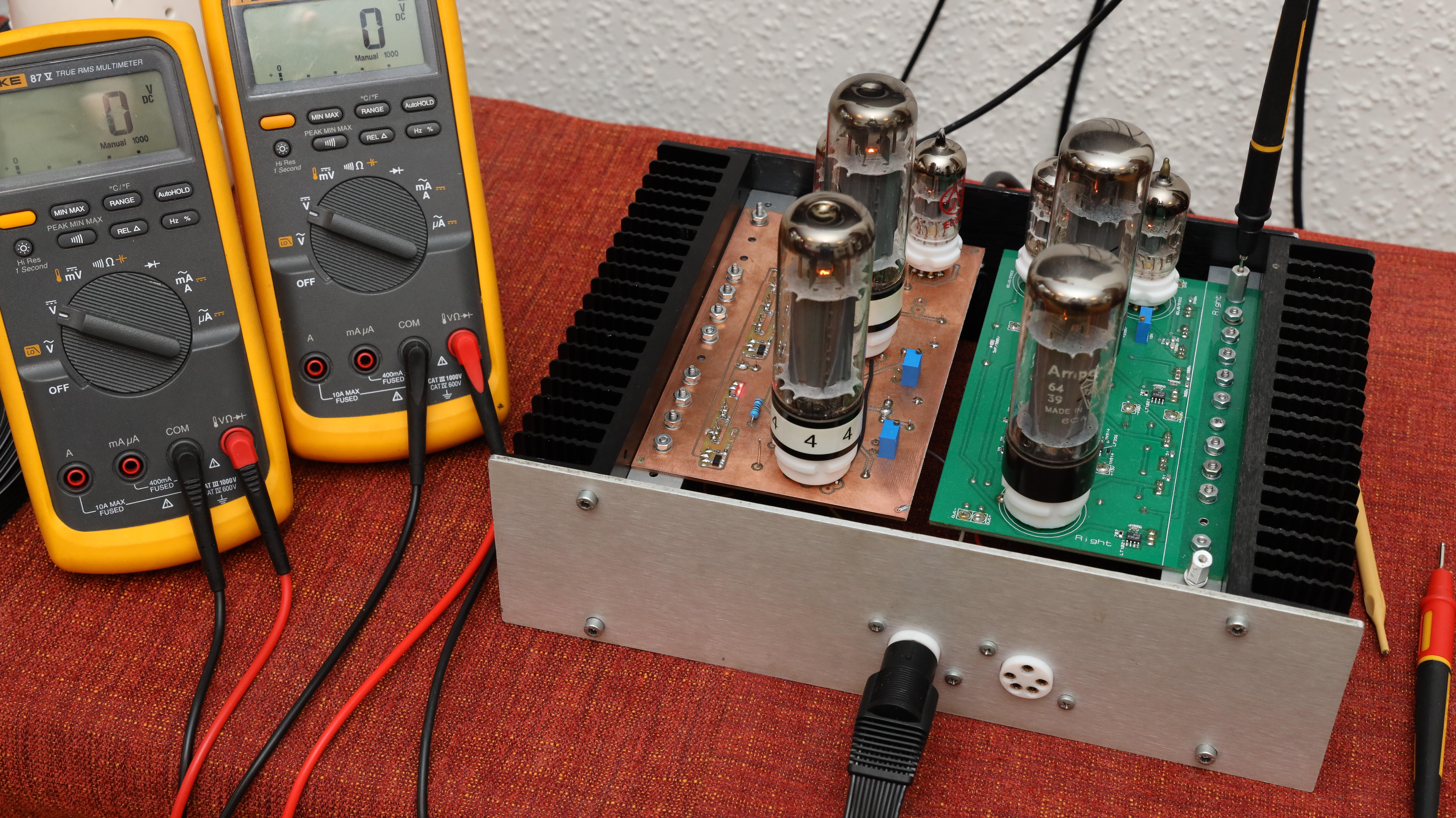
Here is one of my mini T2. Left channel is changed to this… A Megatron something. Upper EL34 changed to T2 style CCS with 3 x 2SC4686 and 01N100D driving two LEDs. Current 28mA, cathode resistance 1390 ohm (the 500R resistors and a trimmer). The big black capacitors are Mundorf MCap Supreme silver/gold/oil, expensive but they look nice. My kitchen at lunch time.
.thumb.JPG.091e6e1aab79f34c5c7508021fa91eba.JPG)

.thumb.jpg.0894a4ee426f0998316949b8a68c8128.jpg)
-
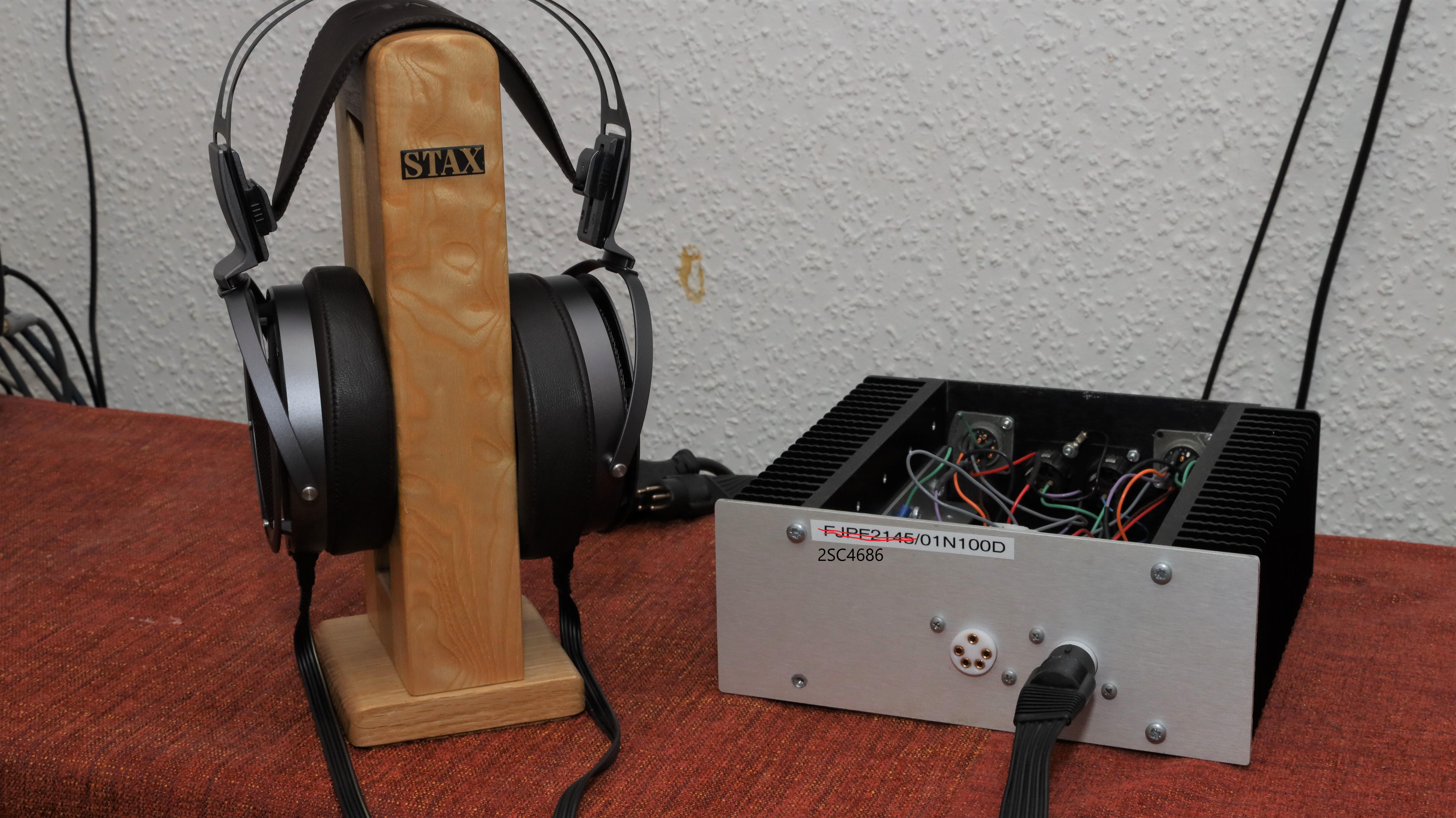
While waiting for the replacement I today brought forward my home-built headphone which has been stoved away for a year or so. It sounds really good, even better than I remembered. Perhaps it ages as a good wine. Wonder what happens if I put it away in our wine cellar for a couple of more years? Original home-built Faulty Stax
.thumb.jpg.95b82d71e3950419b391aa61ba00bf78.jpg) Back in 2011 I bought 50 2SA1486 from www.utsource.net. Price 0.30USD each plus 28USD for FedEx, a few days from China to Sweden. They were green and I haven’t used them at all, but they measure same on DCA75 and DY294 as 2SA1486 from bdent. Anyone tried www.utsource.net ?My condolences to you and your family, Steve.I’ve tested two dozen 2SA1486 randomly out of my small supply with same meter as you. I get roughly hFE at 60 - 70 and VBE at 0.60 - 0.65V. If possible, test breakdown voltage. Some of us use transistor tester DY294 for that purpose. Your measurements diverts to much for my taste… even compared to datasheet...A small project I did some time ago. DIY solder station for Weller WMRP soldering pen. Check this http://kair.us/projects/weller/index.html . I ordered ten PCBs, same price as for the one I needed. If you want to try this, ping me and I send you a board for just shipping costs and I pay same amount to Doctors Without Borders. Does it work? Yes, only for fine smd jobs. Have I used it? No, not really. Why build it then? Because you can.
Back in 2011 I bought 50 2SA1486 from www.utsource.net. Price 0.30USD each plus 28USD for FedEx, a few days from China to Sweden. They were green and I haven’t used them at all, but they measure same on DCA75 and DY294 as 2SA1486 from bdent. Anyone tried www.utsource.net ?My condolences to you and your family, Steve.I’ve tested two dozen 2SA1486 randomly out of my small supply with same meter as you. I get roughly hFE at 60 - 70 and VBE at 0.60 - 0.65V. If possible, test breakdown voltage. Some of us use transistor tester DY294 for that purpose. Your measurements diverts to much for my taste… even compared to datasheet...A small project I did some time ago. DIY solder station for Weller WMRP soldering pen. Check this http://kair.us/projects/weller/index.html . I ordered ten PCBs, same price as for the one I needed. If you want to try this, ping me and I send you a board for just shipping costs and I pay same amount to Doctors Without Borders. Does it work? Yes, only for fine smd jobs. Have I used it? No, not really. Why build it then? Because you can..thumb.jpg.76341cd7da173c04bdea2c03e0101ab5.jpg)
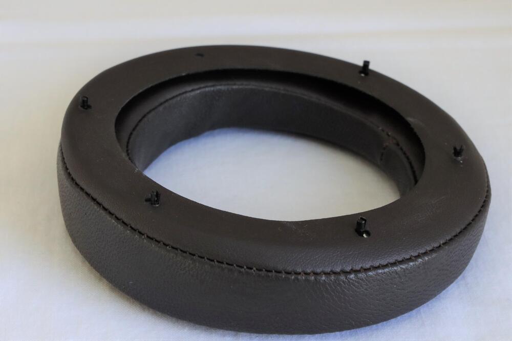
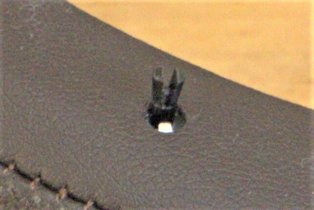
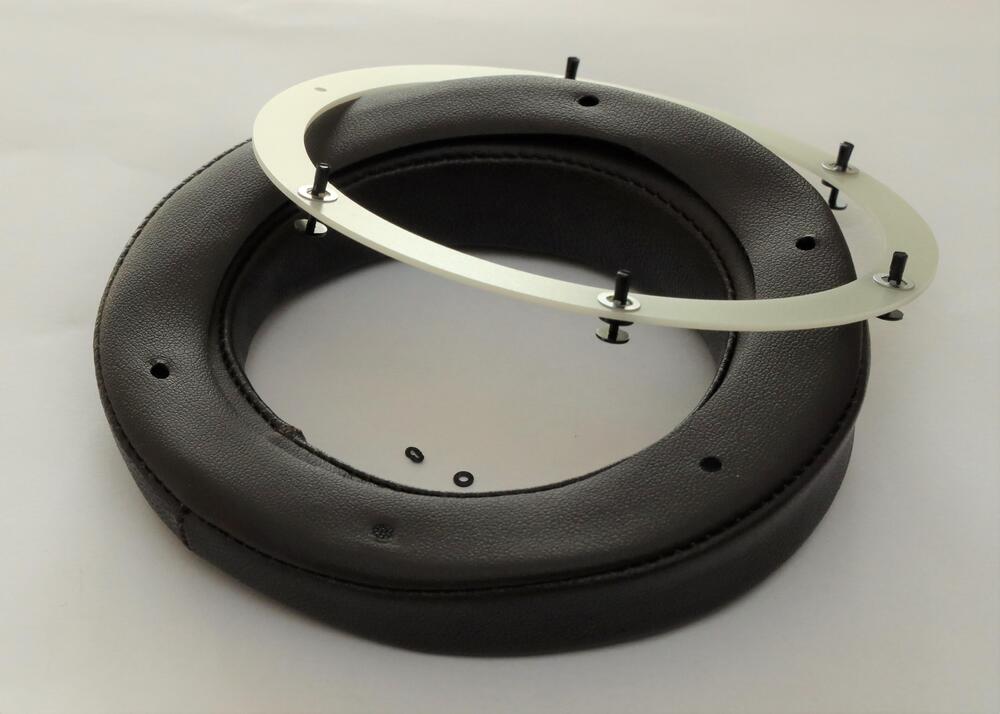
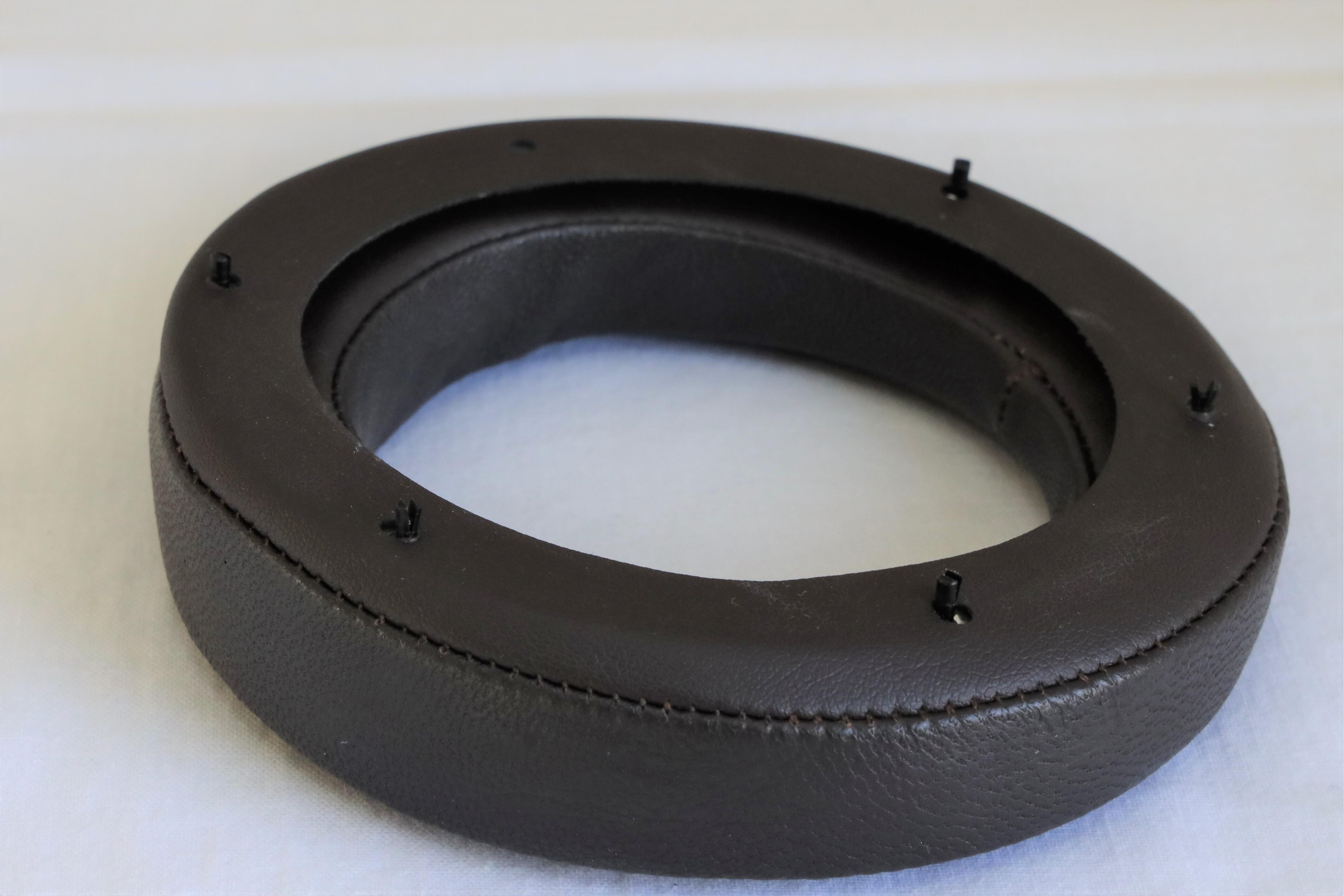
.thumb.jpg.cc7c2ef9044614505777ae76de0e5fda.jpg) Excellent, thank you @Kung. The evidence is clear. There are foreign objects, most certainly the cause of the problem. A replacement is on its way. My supplier is very helpful$$$Happy Birthday!Happy Birthday!It’s a small rip, a couple of millimeters. I guess a return for repair is the only option. But the headphone is not completely useless. I use Roon and its signal processor, -12dB on good side and +6 dB on bad (damaged) side. Playing at low to normal level the headphone sounds really nice. I imagine the small wound will grow larger by time. Changing the cable on 007 shouldn’t be a problem (knock on wood).Well… I’ve finished the work with the new headphone and it ended in a disaster. I decided to resolder all solder points, so I took the driver package a part. Even removed the small cable connector. After cleaning all solder points, I connect outer stator and put into its position. It was a bit tricky to arrange the short wire in the connector house. Next was the diaphragm and here I made the disastrous mistake and got a scratch on the membrane when I should solder its wire. I guess I’m getting to old and clumsy for this kind of delicate work. Nowadays I have to wear headband magnifier which also makes it more difficult. Anyhow, I finished the assembly and have one good side and one bad with a small defect on membrane. After visual inspection with good light and magifier I don’t think the lower loudness had anything with dust or any foreign particles to do nor bad connections. So, I really should had waited for this… Thanks a lot, Wachara and Birgir!It seems I’m running out of luck. SR-X9000 was the best headphone I’ve listened to only for a couple of days. You better keep your Omega, Andy. Today the Stax have a terrible unbalance. Left side is more than 12dB lower then right side. It was left side I opened, lifted inner stator and flipped as you see on picture a few posts above, removed plastic ring and easily lifted the diaphragm and gently held (didn't touched the membran) it in hand for a short while before I put it back. Could that be the reason or is just an unfortunate coincidence? No worry though. It’s a calculated risk and mostly nothing bad happens. If just had been something cheaper. 😭Sorry Andy, no review or opinion from me. We have to wait for the trusted - Birgir. I just tear things down, a bad habit. P.S. I think SR-X9000 is the best headphone I’ve listened to. I haven’t listened to original Omega or HE90."Diaphragm" side of stator. Zoom in and you can see the structure of net (copper??). Stator with plastic ring. Outer diameter 94mm and inner 84mm. Thickness of diaphragm ring is 0,95mm on my digital caliper, so I would say spacer thickness 0,5mm. To me spacer material looks like aluminium.
Excellent, thank you @Kung. The evidence is clear. There are foreign objects, most certainly the cause of the problem. A replacement is on its way. My supplier is very helpful$$$Happy Birthday!Happy Birthday!It’s a small rip, a couple of millimeters. I guess a return for repair is the only option. But the headphone is not completely useless. I use Roon and its signal processor, -12dB on good side and +6 dB on bad (damaged) side. Playing at low to normal level the headphone sounds really nice. I imagine the small wound will grow larger by time. Changing the cable on 007 shouldn’t be a problem (knock on wood).Well… I’ve finished the work with the new headphone and it ended in a disaster. I decided to resolder all solder points, so I took the driver package a part. Even removed the small cable connector. After cleaning all solder points, I connect outer stator and put into its position. It was a bit tricky to arrange the short wire in the connector house. Next was the diaphragm and here I made the disastrous mistake and got a scratch on the membrane when I should solder its wire. I guess I’m getting to old and clumsy for this kind of delicate work. Nowadays I have to wear headband magnifier which also makes it more difficult. Anyhow, I finished the assembly and have one good side and one bad with a small defect on membrane. After visual inspection with good light and magifier I don’t think the lower loudness had anything with dust or any foreign particles to do nor bad connections. So, I really should had waited for this… Thanks a lot, Wachara and Birgir!It seems I’m running out of luck. SR-X9000 was the best headphone I’ve listened to only for a couple of days. You better keep your Omega, Andy. Today the Stax have a terrible unbalance. Left side is more than 12dB lower then right side. It was left side I opened, lifted inner stator and flipped as you see on picture a few posts above, removed plastic ring and easily lifted the diaphragm and gently held (didn't touched the membran) it in hand for a short while before I put it back. Could that be the reason or is just an unfortunate coincidence? No worry though. It’s a calculated risk and mostly nothing bad happens. If just had been something cheaper. 😭Sorry Andy, no review or opinion from me. We have to wait for the trusted - Birgir. I just tear things down, a bad habit. P.S. I think SR-X9000 is the best headphone I’ve listened to. I haven’t listened to original Omega or HE90."Diaphragm" side of stator. Zoom in and you can see the structure of net (copper??). Stator with plastic ring. Outer diameter 94mm and inner 84mm. Thickness of diaphragm ring is 0,95mm on my digital caliper, so I would say spacer thickness 0,5mm. To me spacer material looks like aluminium..thumb.JPG.c549761b5fac70205bd09bcbf57bc57f.JPG)
.thumb.JPG.22494018e114424d4d15438f75d45525.JPG) This broke after a couple of years. But a piece of aluminum and 2 component epoxy fixed it and a cnc milled small PCB replaced another broken original part.
This broke after a couple of years. But a piece of aluminum and 2 component epoxy fixed it and a cnc milled small PCB replaced another broken original part..thumb.JPG.8ded12970550dd8df38ff4b0be0dee21.JPG)
.thumb.JPG.1bec5870e66727e3a4054b649a50063f.JPG) Until trusted person gives a reliable review here, you might study the interior of the new Stax SR-X9000. I let the pictures speak for themselves.
Until trusted person gives a reliable review here, you might study the interior of the new Stax SR-X9000. I let the pictures speak for themselves..thumb.JPG.83220d0878997b35ffc3bdc931b32664.JPG)
.thumb.JPG.c2dda9a851e621c9590b085a61e538c5.JPG)
.thumb.JPG.87c4214745c446a4ebab13b2881a7ac1.JPG)
.thumb.JPG.9b8b92c7b2903195cb265eebe5d91fd2.JPG)
.thumb.JPG.b83e2299b84b9c1738fad9e260430fa8.JPG)
.thumb.JPG.eff13445b5f6611dde20b6c0d40e2c82.JPG)
.thumb.JPG.73fdaca14c51616b83f82bd5d7c66235.JPG)
 The new Stax just arrived. Sorry for posting in CRNB thread.
 Tomorrow before 6pm Swedish local time, according TNT.Years ago I had problem with high temperature when stacking two transformer. It was so high so upper transformer started to “boil”. I bought some BERGQUIST GAP PAD VO Soft, 3mm thick, from Mouser. One piece between lower trafo and 3 mm aluminum bottom plate, one between trafos and finally one between top trafo and top aluminum plate bent and bolted to heat sink. This way the temperature was reduced considerable. Determine inner temperature of a transformer is not easily done. One way is the measure resistance of primary winding when cold and when hot. Put those figures in this formula, T(hot) - T(cold) = [[R(hot)/R(cold)]-1] x 235 and voila.. you have calculated the temperature raise of the transformer.Early draft of a modified Megatron. Top EL34 is replaced by 3x2SC4686 and a 10N100D. Less transformers – reduced risk.
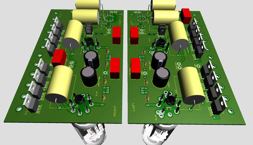


.jpg.daf1a7eb8df8d4c6722e955d00faa993.jpg)


.JPG.14e596f25c456e340489f507c9ce80d6.JPG)
.jpg.311f0f3ecd27d1b1f9b2db86354af05f.jpg)


.jpg.a6b40fc14d07772cdcba944e2d0fdb8b.jpg)
.jpg.ba903801091e122f93861676e819fdd2.jpg)
.jpg.5a2398c7855199775e0527a8d06af03d.jpg)


.JPG.10464d3d97612599fc9865b632b1a06c.JPG)
.JPG.ff14255e51b2775a708401167fdf532a.JPG)

.JPG.088a30a35b773609542f95e9c37fbb16.JPG)
.JPG.5a98250764d1719a3e9914cdd37a395b.JPG)
.JPG.b73e3d822b4d18bdcd6e26faaf8a93e2.JPG)
.JPG.08ea71c77054712d5d2e5318beaf7f32.JPG)
.JPG.d73a1bd6fae575b4b59a8f14bcd20438.JPG)
.JPG.a0612ef5614d2e4ee40c2bce5523f9cf.JPG)
.JPG.8b54a0de03bb04c81681165e03898067.JPG)
.JPG.bab4141d4273c91f2e5dd51d649d2fdf.JPG)
.JPG.ccc38c089d1505dc1de1d2df393dbc20.JPG)


Important Information
By using this site, you agree to our Terms of Use.