mwl168
High Rollers
-
Joined
-
Last visited
Everything posted by mwl168
-
All except 3 US/CA destined packages have been shipped yesterday. Of the 3 remaining packages, 2 has not responded to my inquiries and 1 has asked for package to be held and shipped later.
-
I bought a matched quad of NOS Winged C Svetlana EL34 from Upscale Audio in preparation for the Grounded Grid build. The 4 tubes have these spec's on their boxes: Tube 1: Bias 40.8, Transconductance 5.80, G2 mA 7.07 Tube 2: Bias 40.9, Transconductance 6.07, G2 mA 7.25 Tube 3: Bias 40.9, Transconductance 6.07, G2 mA 6.70 Tube 4: Bias 40.8, Transconductance 6.18, G2 mA 7.02 So based on the Grounded Grid circuit, how should I pair them up? Would the same pairing work for the Blue Hawaii? Thanks!
-
A few packages including pots and boards have been shipped to US and CA participants. MLA is waiting for the boards that I ship him about 10 days ago. There was delay on my end on figuring out how many boards to ship to MLA because I was not able to ascertain the country of residence of all the GB participants.
-
I saw that and they were offering 15% discount over Thanksgiving and now 10% discount over Christmas which makes their price "acceptable" for those XF2 EL34. I bought some KenRad 6SN7GT from them a few years ago and now regularly receive e-mail informercial from them. The 6SN7 I received seem fine. Cannot speak to the XF2 EL34 though. Anyone has experience with them and can vouch one way or the other? I did pull the trigger on a quad of NOS Tesla EL34 with Brent. Anyone has experience with these tubes and can share your impressions?
-
Only received three responses so far about shipping option. Two of these will be shipped today. I will be leaving on a long trip in two weeks and would like to process all the US/CA shipments before I leave to avoid long wait so would really appreciate prompt responses. Again, flat rate USPS priority shipping option is $6.8 USD plus $1 for each of the pots you ordered for US destined packages.
-
What do you all think of Charles Hansen's (of the Ayre fame) article below about PCM vs DSD? I am a big fan of his early Avalon speakers so tend to pay attention to what he has to say... http://www.ayre.com/insights_dsdvspcm.htm
-
Exchanged e-mails with Brent. He does not have enough XF2 Mullard EL34 on hand to make a matched quad at this time.
-
Anyone know and can recommend reliable sources for NOS XF2 Mullard EL34? What's reasonable price to pay for a matched quad? Have been thinking about getting a set so I don't kick myself 5 years from now...
-
I am ready to ship the US/Canada destined orders. $1 USD for each TKD volume pot will be added to the postage to cover the shipping from MLA to me. For Canada destined packages I‘ll need to get quotes from USPS based on weight/destination and PM each individual. For US destined orders we can either do the same or we can use the Flat Rate Priority Mail option which will be $6.8 USD per package. I can check other options but given that, except for sbelyo, everyone has one or more volume pots so order need to be sent as packages, by the time we add the cost of shipping container/envelop the saving is likely amount to 1 or 2 dollars. For those that prefer to go with the Flat Rate Priority shipping option, please PayPal me $6.8 USD plus $1 each for the pots you ordered. Please remember to include your shipping address and HeadCase ID if you have not already done so previously. My PayPal ID: If you prefer to go with the weight-and-calculate method please let me know either by responding to this post or PM me. Thanks!

-
On my builds, which are all balanced inputs with Neutrik XLR connectors, I tie PSU ground to the chassis ground (star ground) which is then tied to the AC ground. No ground connection between the input XLR and the amp's input. The input XLR ground pin is tied to the chassis as is suggested by the white paper "pin 1 revisited" by Rane. For my Carbon which has the GR LV and GR HV PSUs, I run a heavier gauge wire between the ground of the two PSU and run one of the PSU's ground to the star ground. Seems to work very well for me.
-
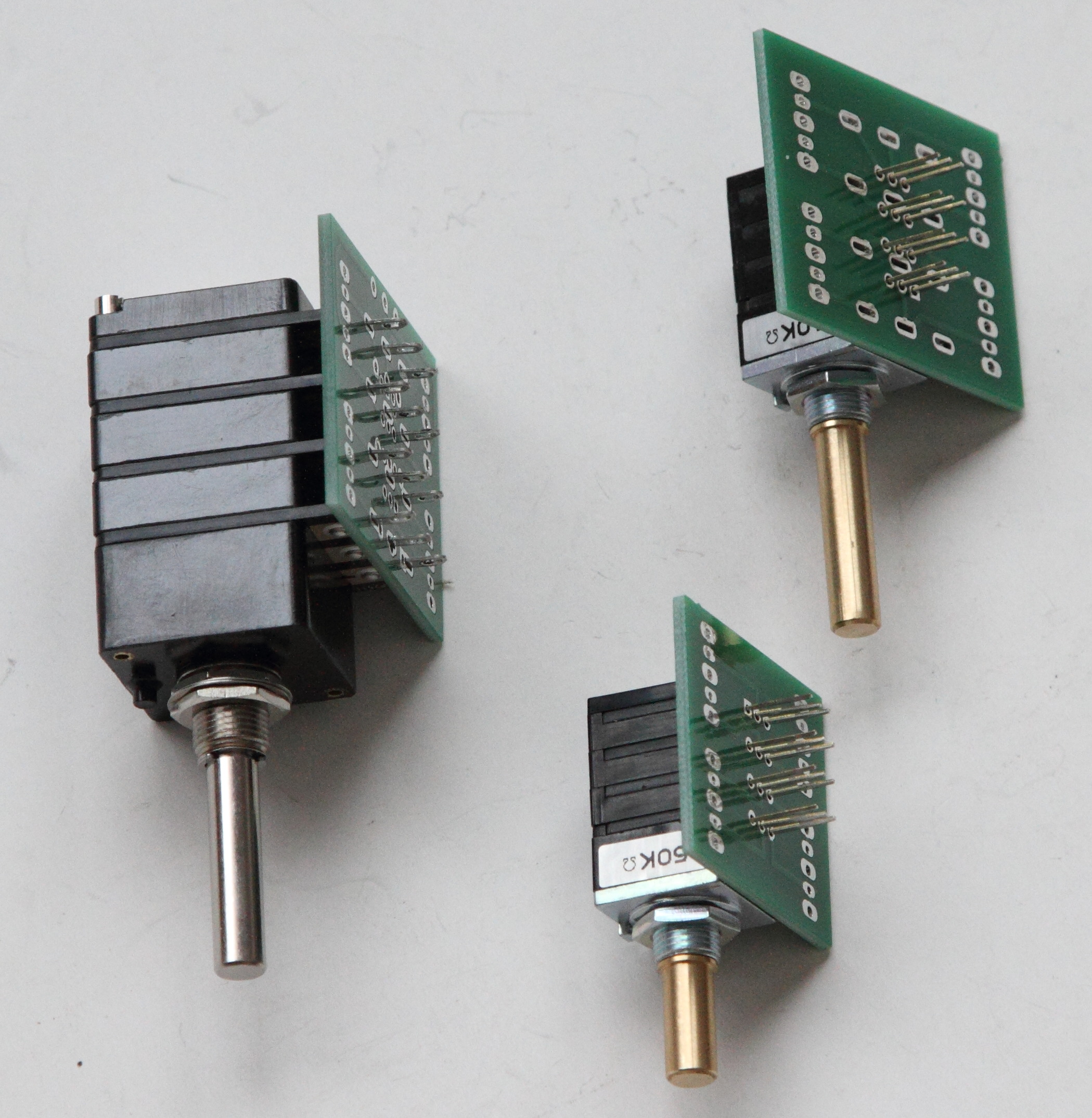
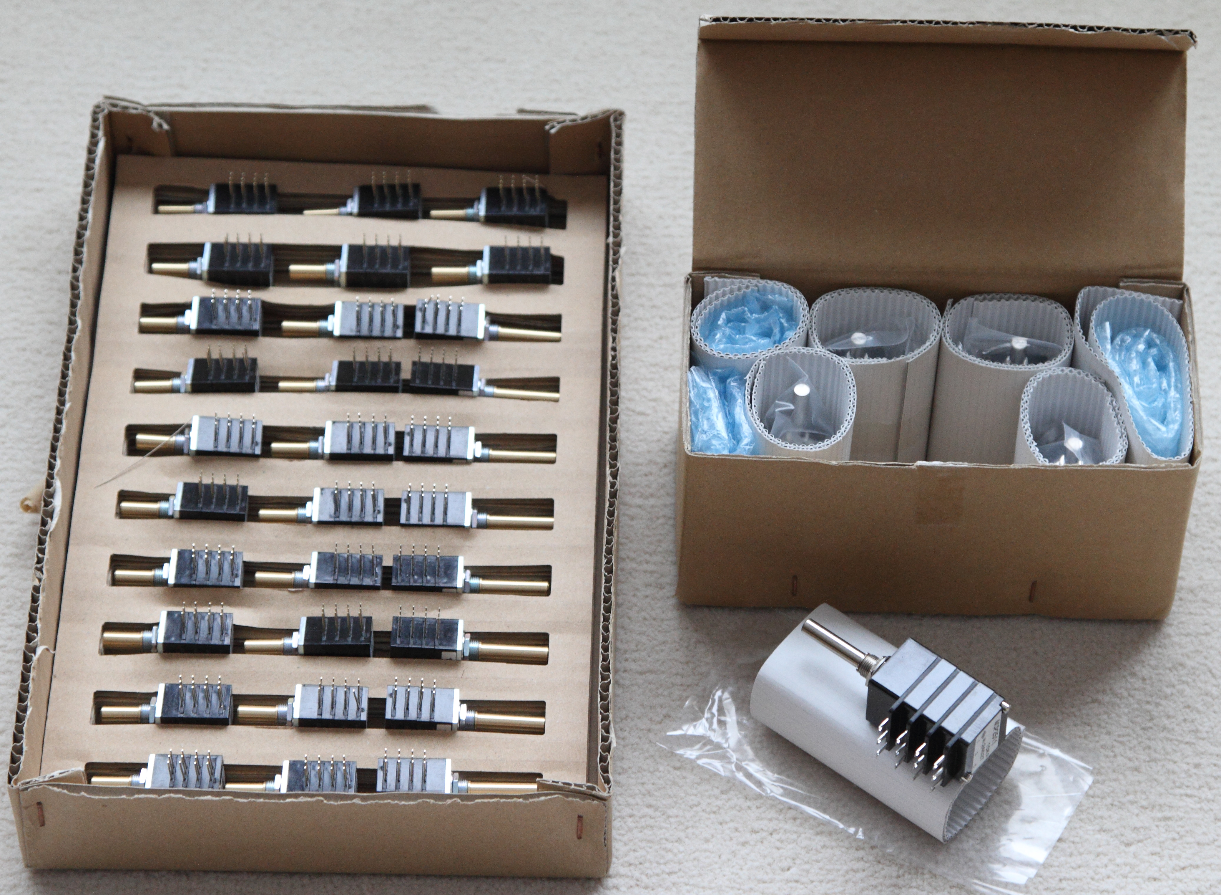
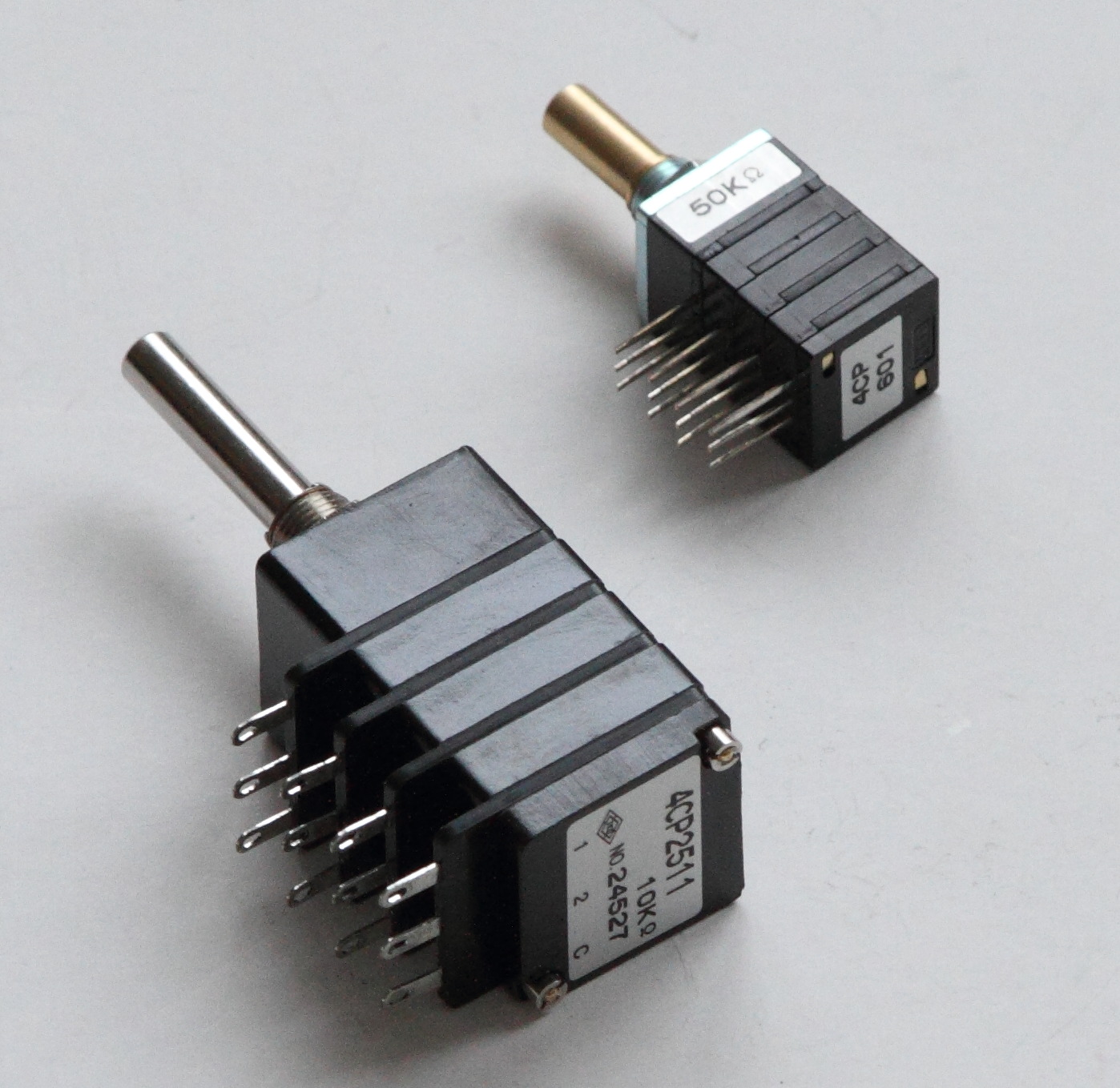
Received the US/CA destined pots from MLA yesterday. The pots and boards fit perfectly as can be seen in the pic below. Many thanks to Pars and MLA for their great work! Still waiting for a few board payments but soon as MLA and I figured out the shipping charge I will notify the US/CA GB participants of the final shipping cost and start sending pots/boards out. The shipping charge from MLA to me will be evenly spread between each pots I received. So far, we have one participant who did not respond to multiple payment reminders for pots and boards and will be stricken from the GB.


-
Since the input to the two channels' tail current sources are on the same connector on the amp board marked as -20VDC input, how do you recommend wiring the two 220K ohm resistors from B-? Also, I assume the 220K resistors would need to be 1W or higher given the voltage drop across them?
-
Where are the pics? It's your own rule
-
If you turn the volume pot all the way up wouldn't that serve the same purpose as bypassing the pot?
-
for V+: (R8 + R7) / R7 x 10 (reference voltage of D5 - LT1021-10), R7 = 1.5K, R8 = 750 for + 15VDC for V-: (R9 + R10) / R10 x 10 (reference voltage of D7 - LT1021-10), R10 = 1.5K, R9 = 750 for -15VDC On the goldenreference4 board silkscreen, R7, R8, R9 R10 are all 1.5K. R7 and R8 are connected and R9 and R10 are connected. R8 and R9 are the 1.5K resistors closer to the DN2540 on each side of the board.
-
-
I agree. As an example, years ago I read a review from a prominent reviewer on a prominent audiophile magazine. This guy went on to rave about a front-end gear asserting its outstanding bass extension and quality and this all through using a pair of mini-monitor speakers that barely reach beyond 40Hz if that. So much for a rave review...
-
-
-
@ nopants: the Galaxy has what is referred to as "quasi heatsink" which the GR HV is attached to. I can barely detect a temperature rise after a few hours running in 70 F ambient temperature. My Antek trafo has 325vac secondaries (IIRC) that is regulated down to 400VDC so the voltage drop on the pass transistors is not too severe. @ JoaMat and UFN: yes, no volume pot I rely on the digital volume on my TPA Buffalo DAC. It's a controversial topic I know but it does save me a bundle of $$$ @ GeorgeP, Birgir and Kevin: yes, I don't like the idea of using male connector on the chassis end either but that's the only way this Y2M-7TK connector comes to my knowledge. I have been searching for some connector covers to use for this reason but have yet to find any that fits. May have to bite the bullet and sprint for the Ampheno connectors some day.
-
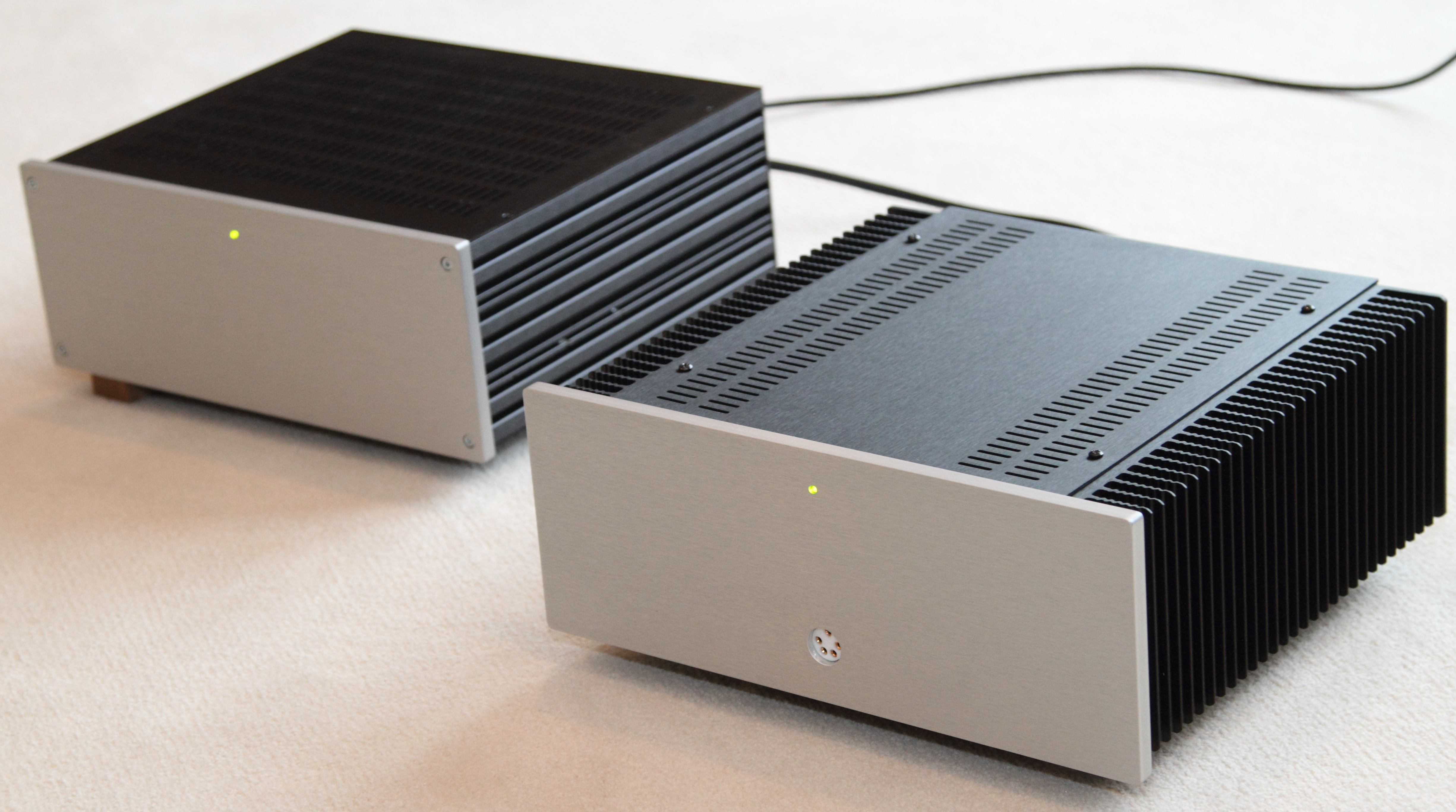
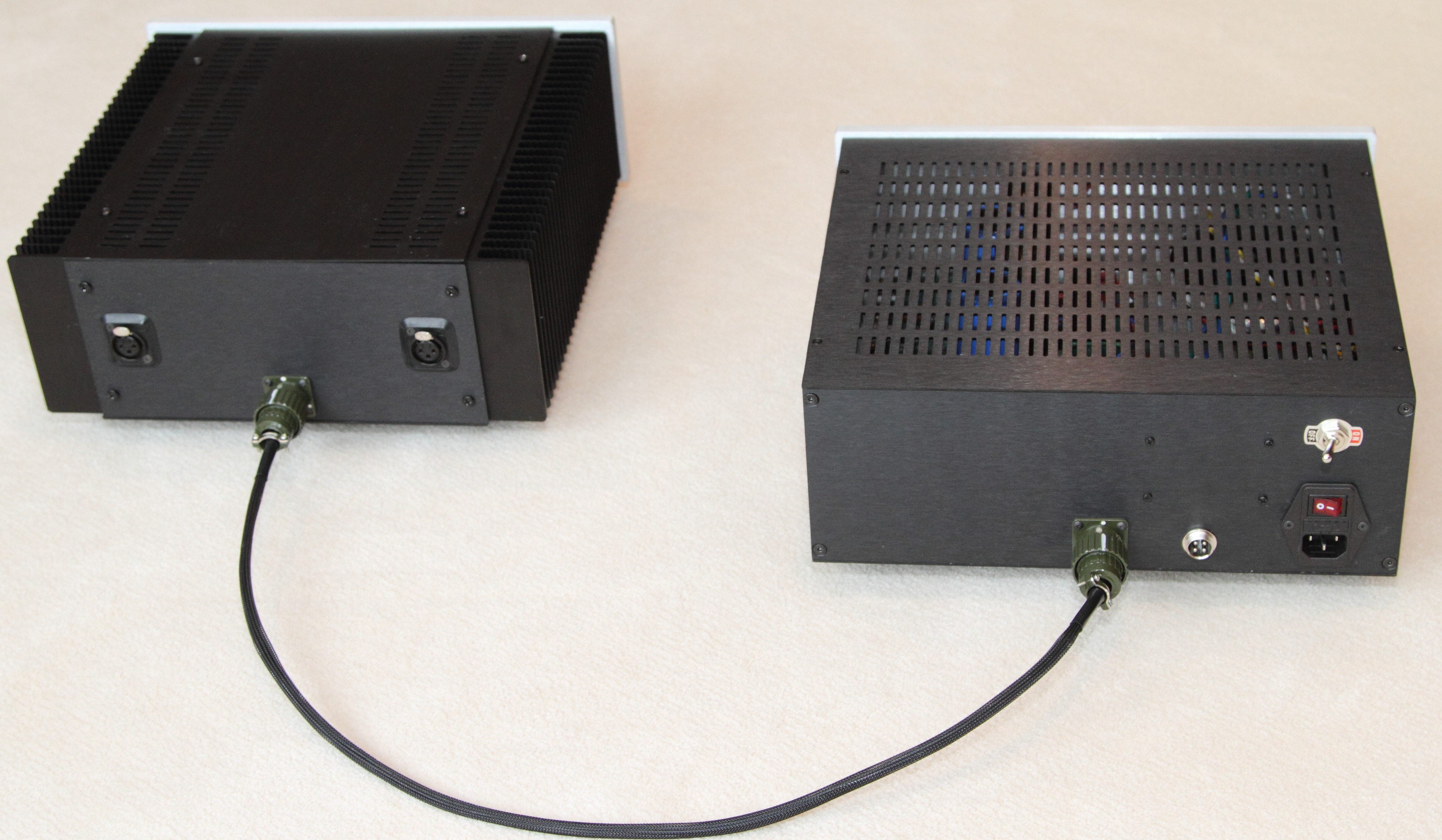
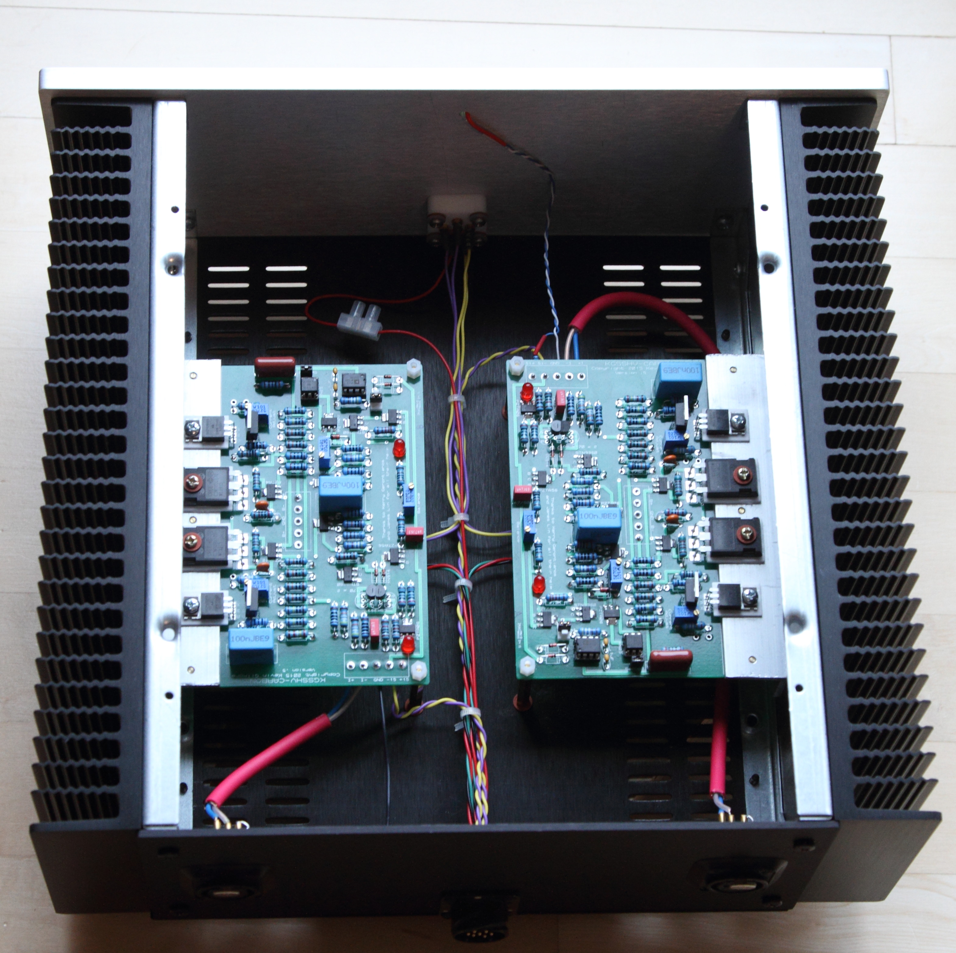
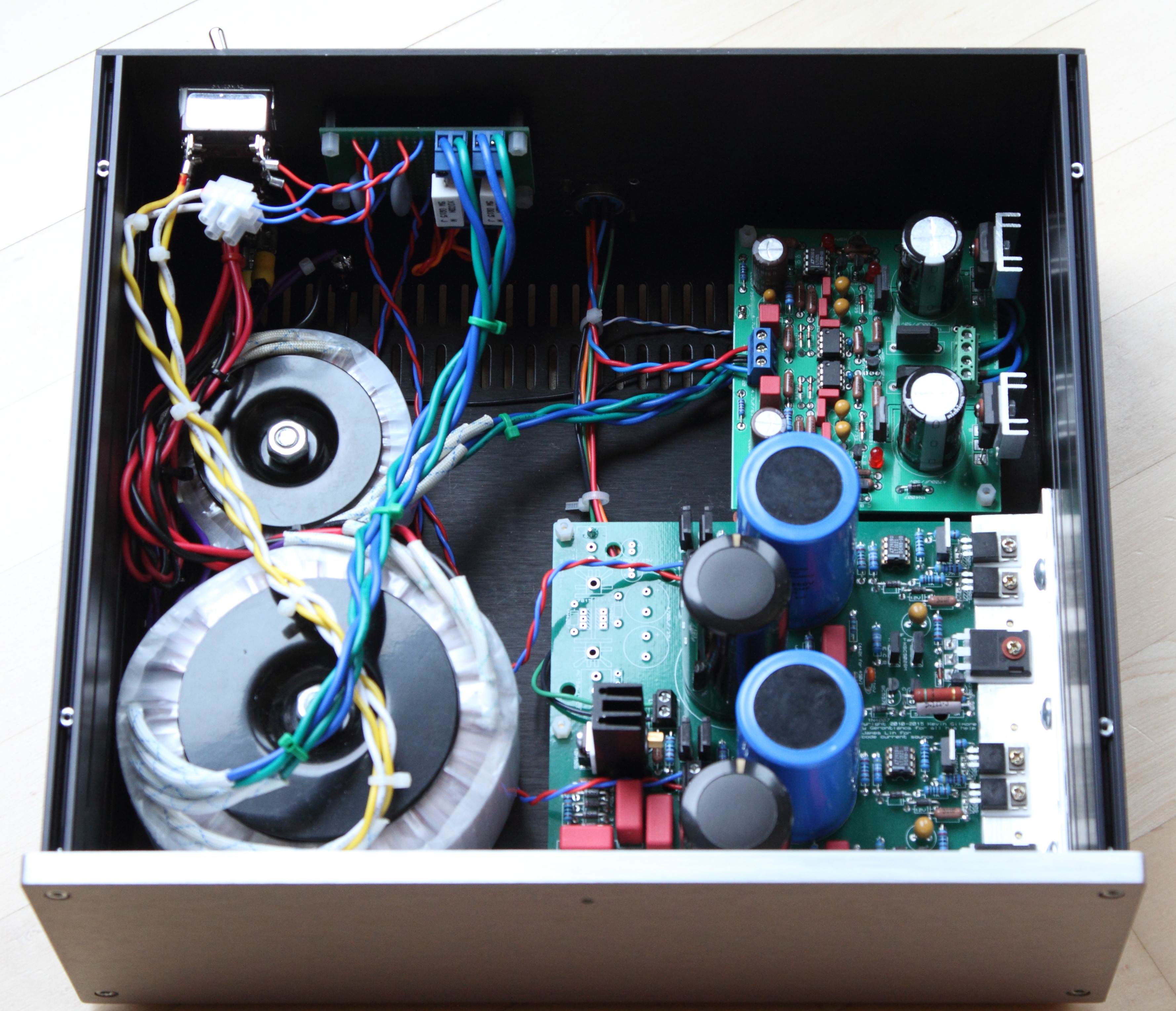
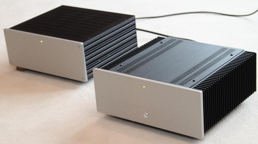
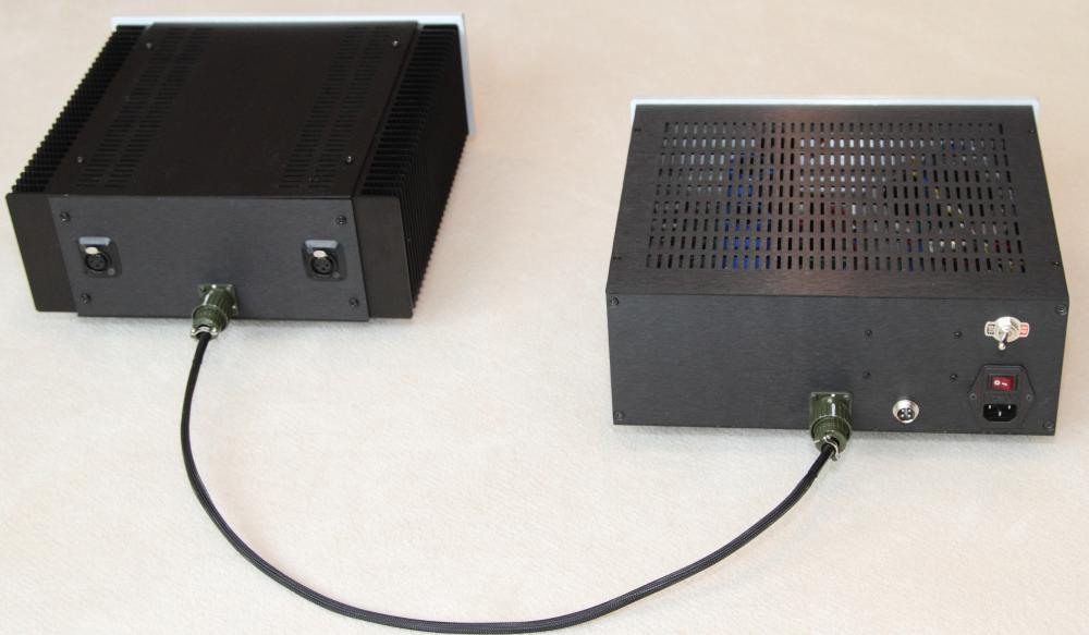
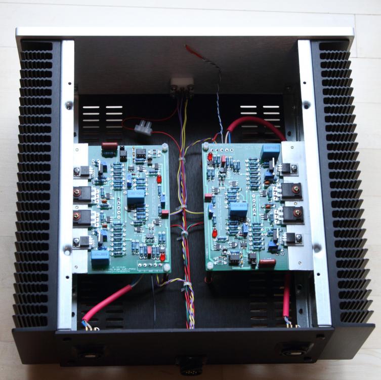
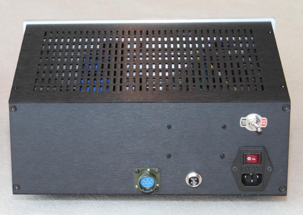
Finally finished casing my Carbon. Apologize for the quality of the photos, the lighting condition isn't ideal. I went a different route - have the amp and PSU in separate chassis and set up the PSU as an "universal" PSU which I plan to use for the Carbon, the KGSSHV, the Blue Hawaii and, in the hopefully near future, the Grounded Grid. I used two off-the-shelf Antek transformers. The secondaries for the HV and filament are on the same 300VA transformer. The toggle switch acts as my manual HV delay and switches the HV secondaries which also have thermistors in series. The 7-pin connector houses the +/- 400VDC, +/- 18VDC and Bias supply. The 4-pin connector houses two sets of 6.3vac filament supply, each set has a 0.15R/5W resistor in series to lower the filament supply to around 6vac to help preserve the EL34 tube life. The amp chassis is a Mini Dissipante 3U and the PSU is a Galaxy 3U. Both with all aluminum panels.

-
Those .22uf/1000VDC caps are coupling caps between stages and directly on the signal path. Quality of the capacitor does matter in that position IMO. I started out with some Wima MKP and later changed to Teflon caps that I happen to have on hand. Good luck and looking forward to seeing pics of your build and your impression of its sound.
-
-
Congratulatrions!
-
Fees paid. Thanks!