luvdunhill
-
Posts
13,727 -
Joined
-
Last visited
-
Days Won
40
Content Type
Profiles
Forums
Events
Everything posted by luvdunhill
-
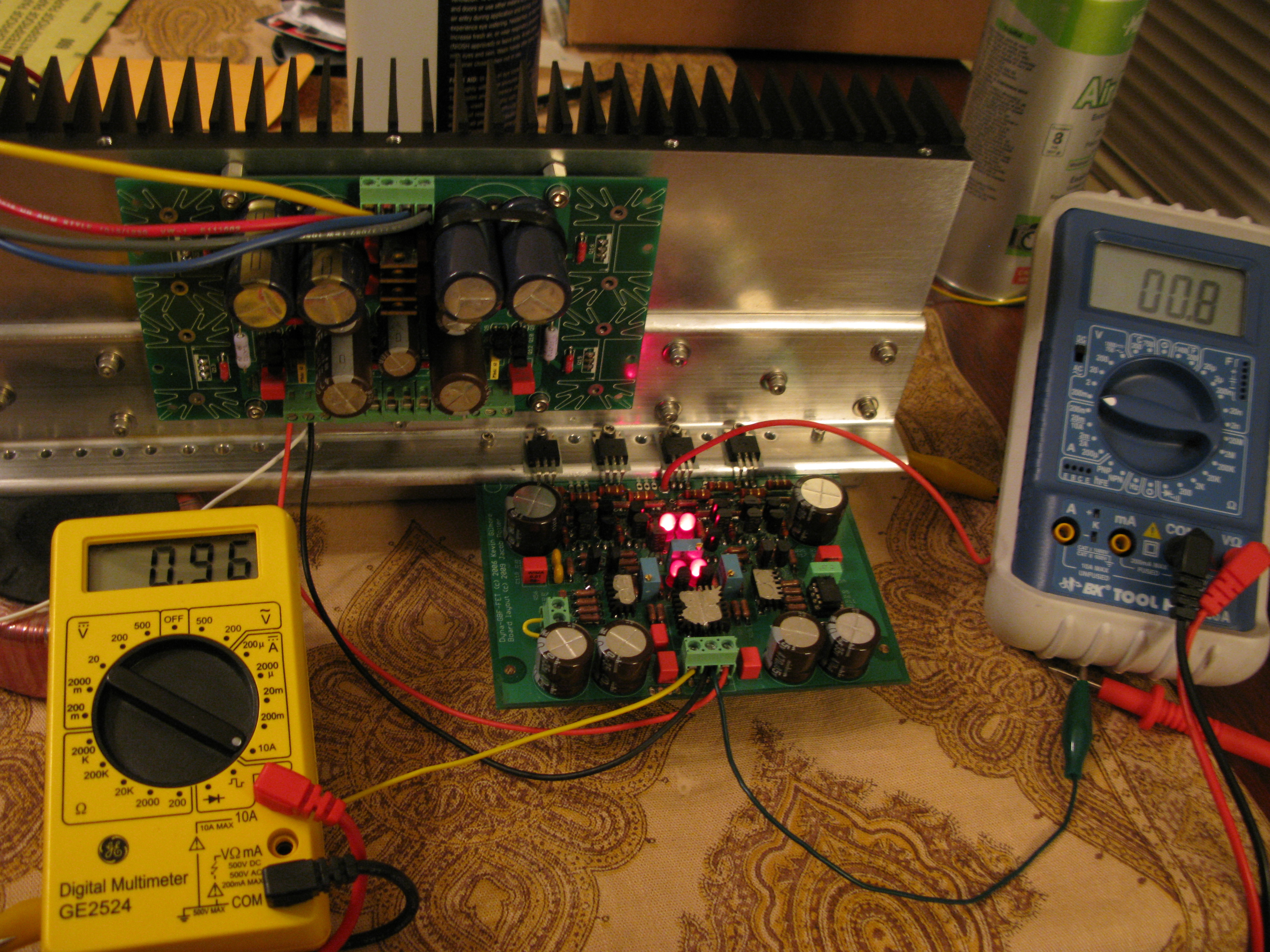
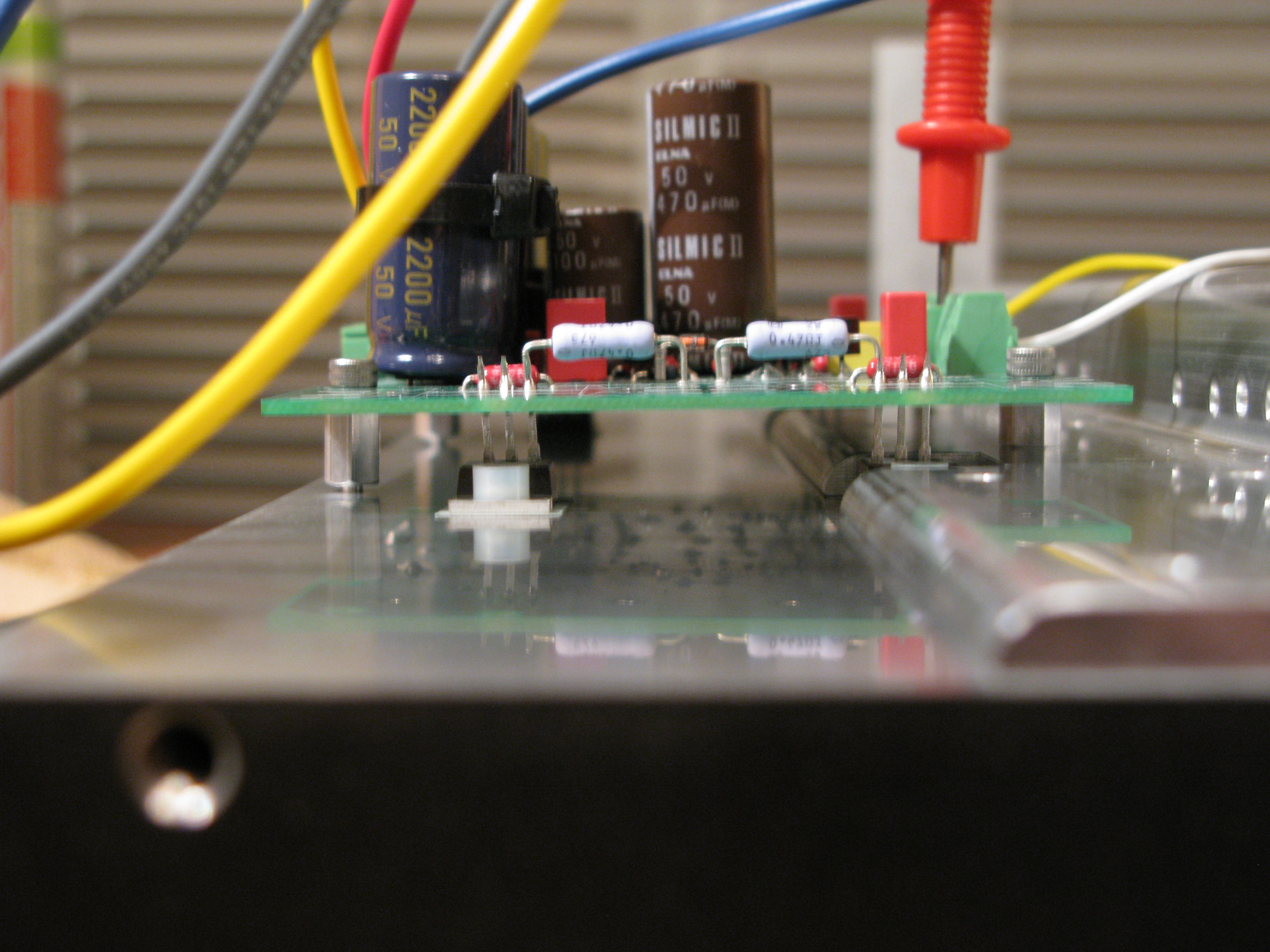
A few numbers for j4cbo and digger945: FETs drawing 329mA, 322mA, 336mA, 315mA. Total draw on negative rail is 710mA. Toroid (160VA I think?) is cold to the touch. Gate voltages 3.39V, 3.22V, 4.55V, 4.57V 2Ω/2W resistors dissipating 0.286W (definitely want to try down to 1Ω, devices are well-matched and we have plenty of dissipation available even at 0.5W.. could stack the resistors and go even lower..) 4.7Ω/1W resistors dissipating 0.001W 10Ω/1W resistors dissipating 0.0002W 221Ω (R27-R30) 1.11V, 1.11V, 1.74V, 1.73V across them I agree with digger945 that we need to work out a solution for lower bias, but I'm pleased as punch so far. I'm assuming we will want to run the same dissipation numbers with around half this current draw, as well as maybe a quarter? I run these same FETs at 70mA in the Blowtorch... but it's a preamp after all. They sound better in this application at 100mA, but I've never had the heat sinking to go higher than that, so stuck with 70mA.
-
I don't quite understand. The gate voltage is directly proportional to the current draw of the output stage. So, you are saying that the thing gets hot? Well, yes it does. How low do you want to go? I'd be willing to try to lower things, but it seems that raising the pot is the ticket, to say 50K? Let me know what you'd like to try and I can give it a go. At this point I'd like to look closely at the buffers and try to get them to run a bit cooler. I need to somehow work on the back side of the board so I can measure some voltages here and there. I'll also get some music flowing for Naaman
-
Conrad MF35-151.5: Conrad Heatsinks - Products
-
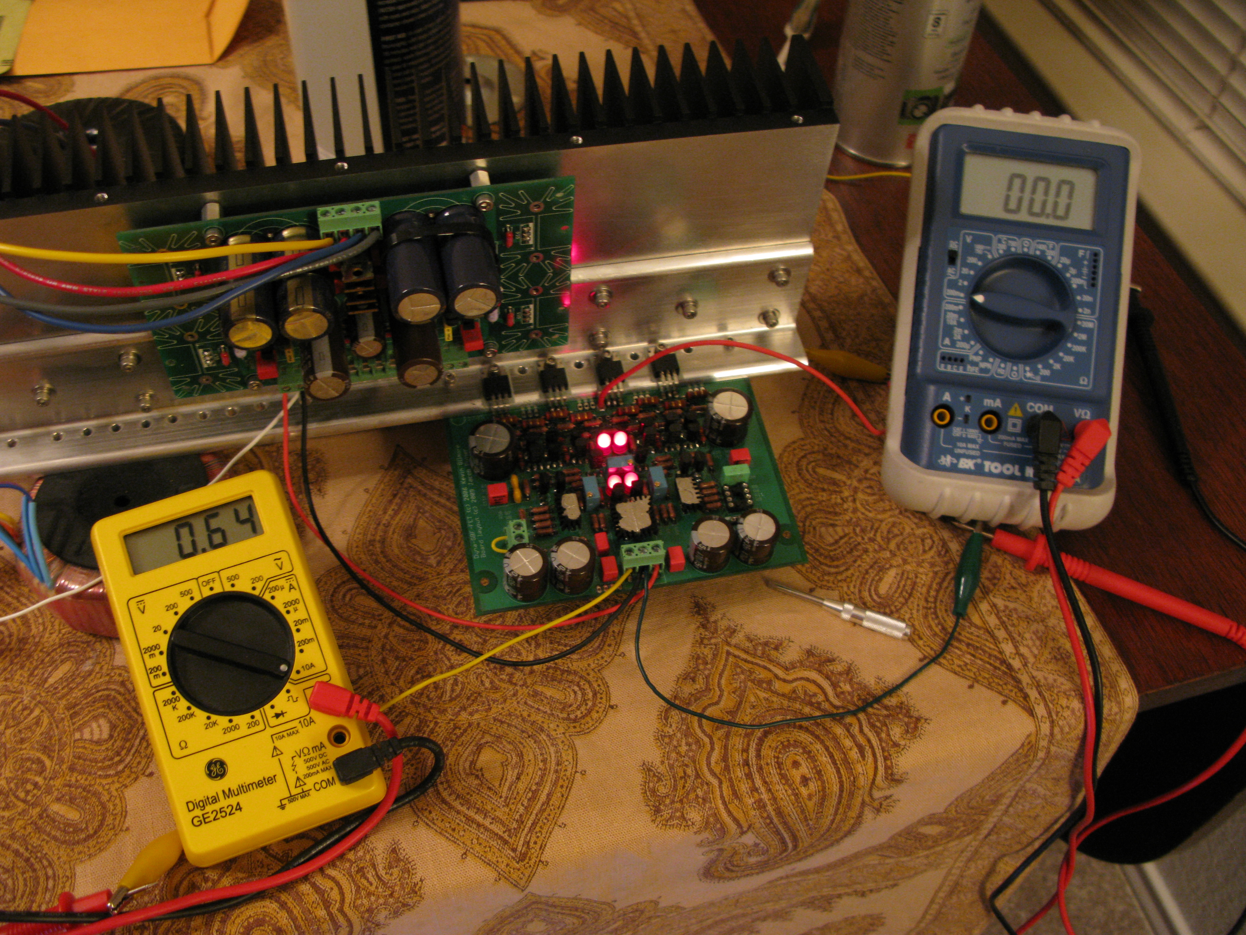
pics. Note current, servo (or lack thereof), and offset. It was actually at 0.00mV for like a minute, so I wasn't trying too hard to get the money shot

-
2mV without the servo. More like +-1mV. even at the lowest bias, the buffers run pretty toasty. So fracking hard to get a probe in edgewise on these boards. Anyone know how much current you can put through a sigma22, assuming unlimited heat sinking for the four MOSFETs? Kinda wish I was using four simga22s
-
hm, pin 6 is 18.3V to ground .....
-
still playing with it. Starts out with 0.1 offset gets down to less than 0.1mV (the resolution of my hand held DMM). This is the trimmers set at 500 and not touched at all. I'd say they are sorta not needed. Much better than my Dynahi version. I'd say these heat sinks are rather perfect, and the long hours of matching are rather worth it. The minimum bias with the 20K pot is 750mA. Lamers may need to up this value. Accidentally had the bias at 3A for a bit... oops. Running at 1A now. The transistors in the buffer are hot, I cannot touch them for more than a second.
-
it works
-
Muse Model 9 Signaure. Wait... crap. I'm half tempted to buy one of the upper end models that will also play SACD... but haven't found a good deal on one and have to free up lots of cash to afford one...
-
Bigger than 19" x 13.77" x 6"? If so, then I must make mine bigger!!!!1!
-
my SACD's arrived... I got an extra one too, but it's a duplicate of one they already sent me :/
-
Jacob: One more thing. You can fit in a three pin Molex connector (similar to the one below C13A) right below C1B, oriented perpendicular to C1B. Connect one pin to ground, one pin to R55 and one pin to R56. Then it would be easy to adjust the gain remotely. Of course a DPDT (or 4PDT) relay or something to keep the signal short here in the feedback would be cooler and fantastic if integrated into the UberController project!
-
Reks Fiat
-
now that's colloquialism failure
-
turn a blind eye
-
that was supposed to be a funny
-
what about the inductive component of the load, after all you're driving a large transformer...
-
check out their posts and see for yourself try this Google Search: "offline." "banned." site:head-case.org
-
I my opinion, any amp used as a speaker amp should have output protection, preferably something active. However, if you want to go passive, a simple capacitor / resistor zobel in my opinion is inadequate for what you're doing and an inductor (RLC) like amb recommends for the beta24 would be a safer option. Since a beta22 doesn't have any output short protection, maybe an active speaker protection device is a better choice.
-
good if you drive 2 miles to work, bad if you drive an hour to work.
-
never heard of any inert metal, so I dunno
-
maybe it has a greater effect on lower level pain signals ya know, it starts clipping at some point or buffers get overflown..
-
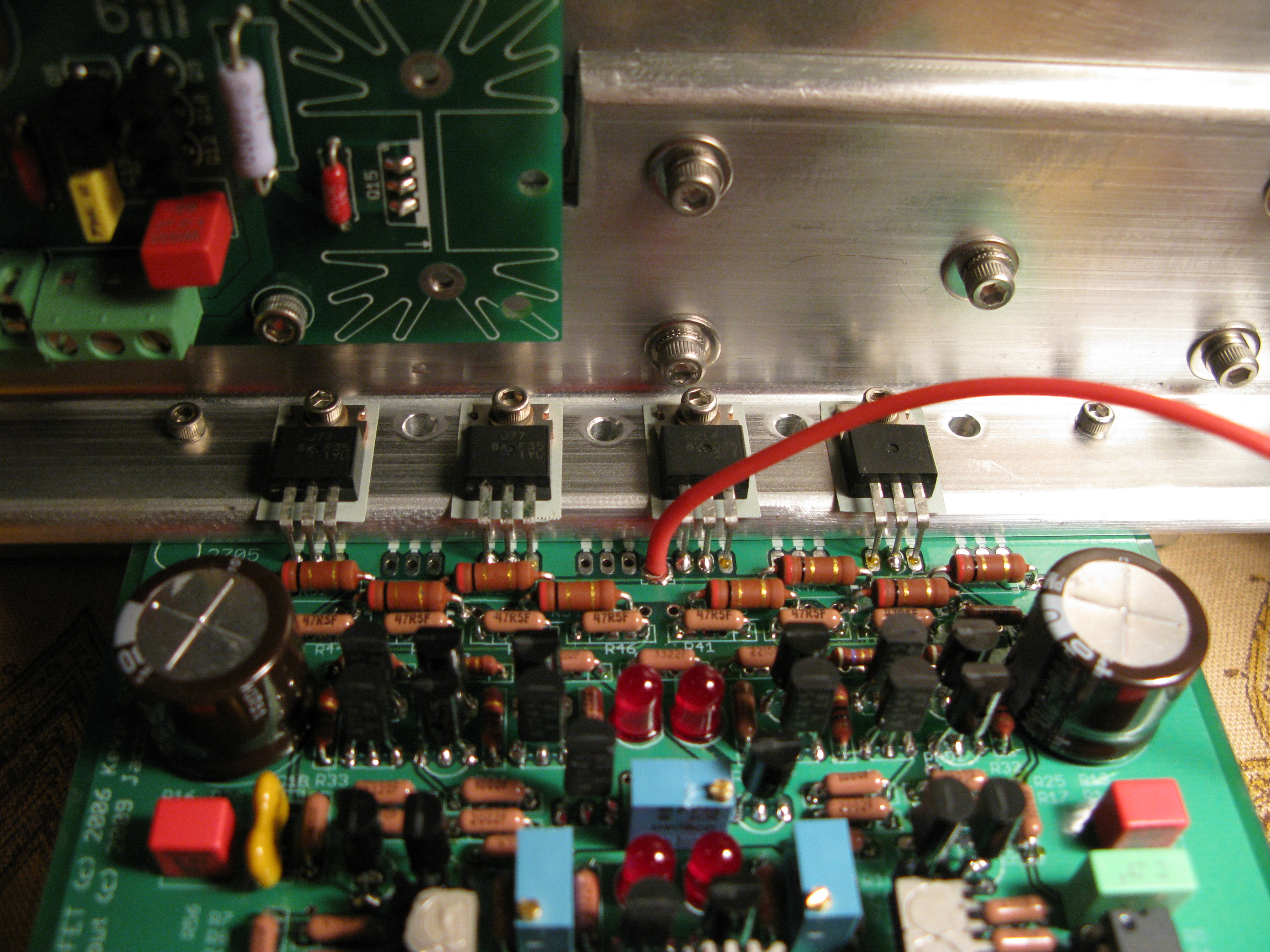
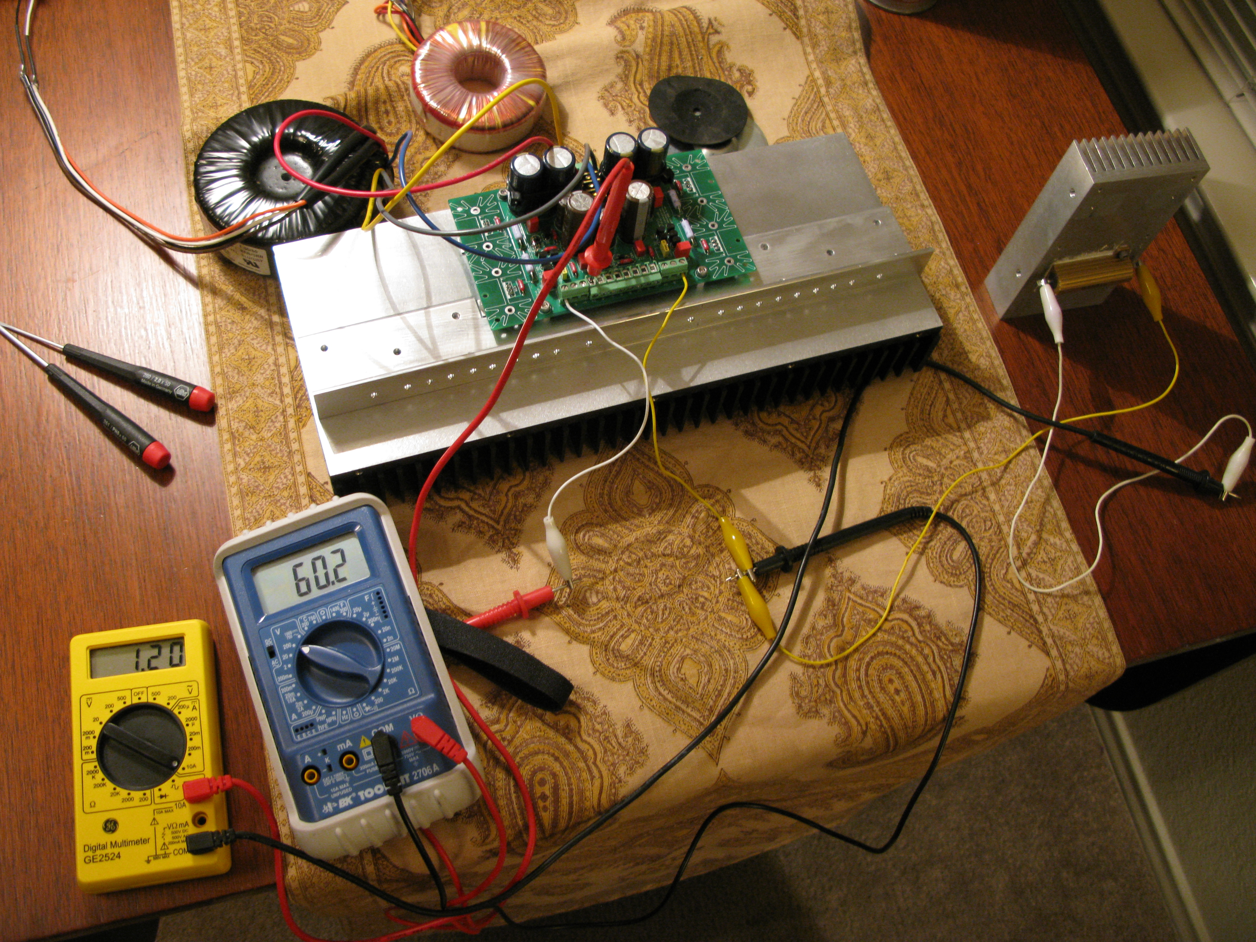
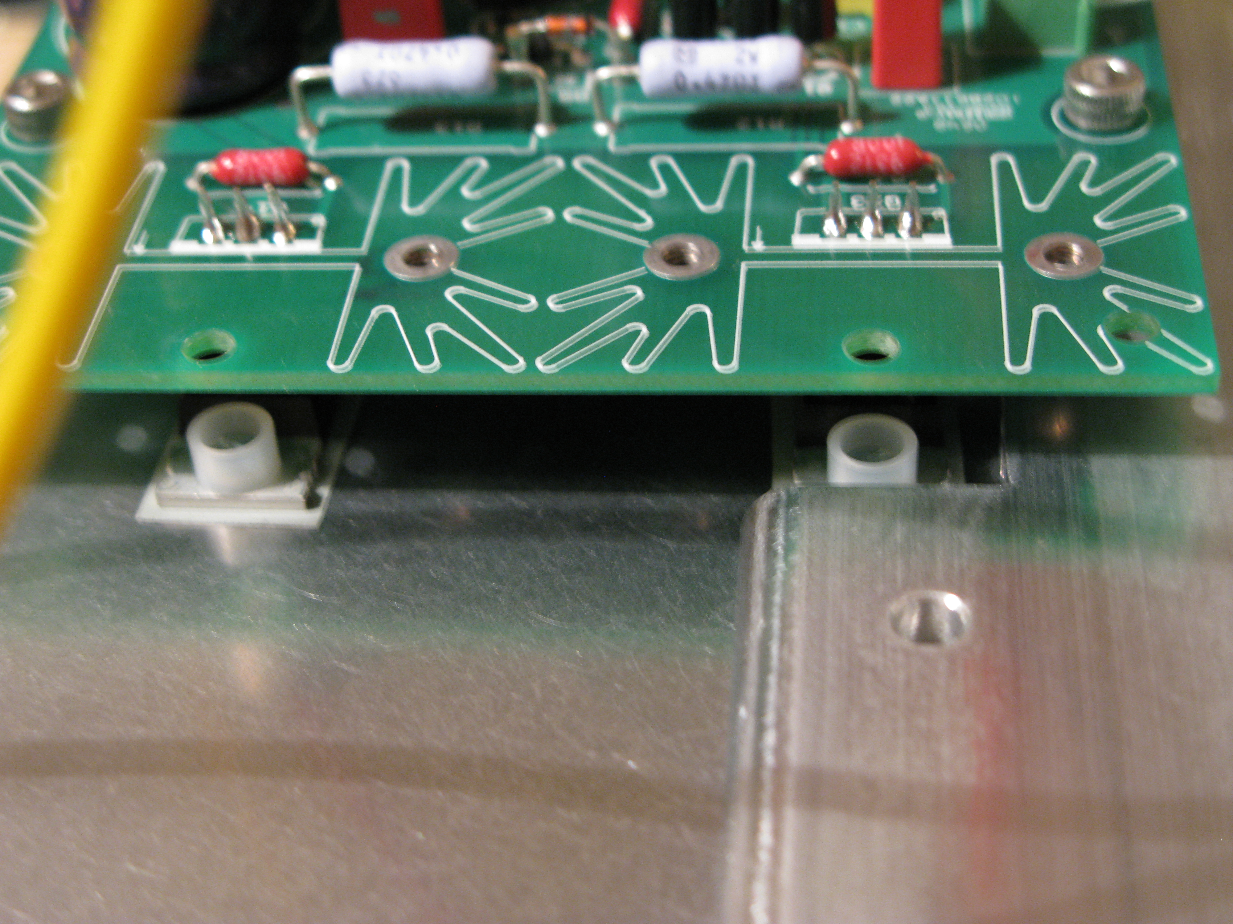
well, after tapping 8 holes at #6 instead of #4 , I had to order some parts from Mouser and they just arrived. Namely, the four #6 standoffs and the nylon clad steel screws. Since I cannot fit a shoulder washer anymore to isolate the MOSFETs, I decided to try some nylon. With these fancy screws I cannot get as much torque as using just plain nylon unfortunately, as the inside screw starts to spin a bit... So, I may go back to pure nylon... Anyways, sorta got lucky this worked out. Perhaps there are some other creative solutions, but I couldn't think of any that didn't require tapping and milling my heat sink and/or bracket. Meters show ~+-30V drawing 1.2A. Things get rather toasty Now to get the FETs mounted to the DynaFET boards and get this show on the road!
-
Think of it this way... That cartridge didn't cost you $5K, and it's doubtfully worth $5K on the used market... There, does that help?
-
Jacob: Would you consider adding a way to mount a small PCB in place of the input transformer? I'm thinking similar to what Nelson Pass does for the UGS boards in his preamps. He uses two banks of DIP pins to connect the daugherboard and you'd route up the necessary I/O signals up via these pins. I have a solid state SE to Balanced design I'd like to try down the road a bit, and it would be nice to just snap it into the boards.