Arthrimus
-
Posts
112 -
Joined
-
Last visited
Content Type
Profiles
Forums
Events
Everything posted by Arthrimus
-
That looks really nice. Well done sir.
-
Exactly and exactly. I sat here for a couple of minutes trying intentionally to get shocked by my SRM-1 Mk2 and couldn't manage it. I'm not sure how you could possibly do it accidentally. Unless he tends to pry the the plug out with a screwdriver, which is actually a distinct possibility since one of the stated goals of his new connector is "easier insertion and removal." I keep asking how creating a new connector that will need adapters is going to fix the supply chain issue that will still exist for Stax plugs and I keep not getting an answer from anyone over there.
-
Ok, I think I inferred that from some stuff I was reading about Audioquest's Nighthawk a while back. Can't find anything definitive either way but I know that biocellulose is widely praised for it's extraordinarily high rigidity in relation to it's mass.
-
Isn't biocellulose both lighter and more rigid than beryllium? I would assume cheaper to manufacture too? The drivers do look impressive.
-
Sorry, I guess my threshold for absurdity is a bit lower than yours. How about this? "it could be made out of a wheel of sharp cheddar and some rusty nails."
-
Hey I said if you wanted it bad enough. I didn't say it was a good plan.
-
Where can I read this announcement? I'm pretty sure that a stax plug could be made out of a block of wood and a some sacrificial XLR plugs if you wanted it bad enough. Not sure what's so difficult about the design. Nevermind, I found it. Simply asinine. I don't see how anyone who is expecting to ramp up even the smallest scale of production on electrostatic headphones couldn't manage to have a run of plugs and jacks made by any of the thousands of willing factories in china. Or even better since Mr Speakers 3d prints their headphones why not 3d print the plugs too?
-
Oh I know. Believe me, that part of the operation is already complete. I installed the six pin sockets last night. I like the daughter board they are using now. The old jumpers between the sockets were far from elegant. Edit: So if I'm understanding you spritzer, I'll basically be building the SRM-1 Mk2 low bias supply. B+ from the 727 is 350v correct? So a voltage divider for this would be B+ into a 180K resistor with a 345K resistor to ground then a .1uf capacitor to ground before a 4.7m resistor to the bias pin.
-
Is there a place on the 727's board where a normal bias line could be tapped? I will be adding normal bias to my amp since I only have normal bias phones right now. I could just tap the 120v line and put in an SRD style bias supply but if there is a place on the board that could be tapped for the bias supply that would require less components that would be cool to know.
-
Cool cool. Then wait I shall.
-
So how violently will an SRM-727a explode if I were to plug it into my healthy 123V USA outlet? Stax is getting really mean these days, my newly acquired 727a is the same revision as charlo89's and the transformer doesn't even have the 120V windings cut anymore, they simply are not even there on this new transformer. I have a step down transformer on order but I'm impatient and foolish. What's the damage if I do it?

-
Thanks so much for the help. I intend to use the KGBH board in it's standard cap filtered configuration so that's the info I needed.
-
So something like this Antek http://www.antekinc.com/as-2t350-200va-350v-transformer/ wouldn't give me enough headroom. I guess I'd have to step up to one of the 400VA models to get anything higher than 350V. Just to clarify, can center tapped transformers be used with the KGBH power supply or do they have to have separate high voltage secondaries? Also I was curious what the max transformer voltage would be safe to use. Antek has some 430V transformers in stock right now. would that be suitable for this application or would that be too much excess for the power supply? Thanks.
-
For those of us who will be building the amp on a KGBH power supply, what specs are we looking for as far as the power transformer? Voltage, current, etc? Thanks.
-
I missed this, I guess I don't check the forum often enough. Sigh. If there are any extras I'd like one. I'm a little iffy on building the shunt regulator board in light of the recent issues.
-

CLOSED - SR-X Plus and JimL Shunt Regulator PSU Boards Group Buy
Arthrimus replied to velvetx's topic in Do It Yourself
Got mine today. Mighty fine looking boards. Looking forward to building the amp. Thanks! -
How is it that Woo can't build a functional bias supply? If I can put one together on perfboard for a couple of dollars using Stax's own schematics surely they could do the same.
-
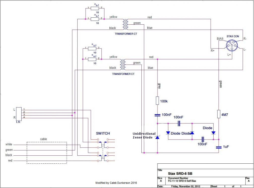
So I know it's been a while since I posted in this thread, but I just wanted to give a quick update. I recently acquired an SRD-7sb unit and was able to confirm that the circuit that I posted further upthread was indeed incorrect, but only insofar as the diode on the far left was not labeled as a Unirectional zener diode just as JimL said. I modified the schematic and built a test circuit using the new schematic and it works great. EDIT: I initially indicated that the Zener Diode should be Bidirectional. This was an error, the Stax circuit uses part # 1Z100 there which is in fact a UNIDIRECTIONAL 100V zener diode. Using a bidirectional diode here causes undesirable effects to the voltage multiplier and will not generate the correct bias voltage. I have updated the schematic below to reflect the change. Sorry about that.
-
Wow, so just 2 pieces of paper cut to size on each side of the diaphragm should do it? Sounds like a piece of cake!
-
I believe it's a zener diode intended to prevent arcing from SRD boxes. It seems that this solution doesn't really work very well. And yes the dust covers are intact.
-
Will do. As a side note, now that I've seen how easy these drivers come apart, I'm curious about doing a pro bias mod. Spritzer, I know you have done one. What material did you use for the spacers? How doable is it for the average guy?
-
I pulled the drivers out of the cups and swapped them to see if the issue was in the cable. Unfortunately the imbalance followed the drivers, but I did notice something strange about the quiet driver. Where the loud driver is shiny the quiet one has a kind of haze on the rear stator. It almost looks like a fungus of some sort. Here are some pictures of what I'm talking about. EDIT: I pulled the driver apart and found NO ARCING! The diaphragm was glued to the rear stator and has some hazy residue on it. I suspect this driver may have been exposed to some moisture or something explaining it's problems. Here's a picture of the diaphragm. I flipped the diaphragm over and reassembled the driver and now I'm getting full output from both drivers! Bass is present too. I think the perceived lack of bass was due to the channel imbalance. The good driver was working properly the whole time. Should I do anything to try and clean the diaphragm and stators, or should I just leave well enough alone and enjoy them now that they are working?
-
I've got a problem that I could use some advice on. I just snagged a trio of SR-X Mk IIIs and boy do these sound sweet. This is the first time I've heard one and I honestly think it might be my favorite headphone right now. All is well with two of them, but the last one is quite sick. It's got some channel imbalance and has very little bass at all. I figured that they may need to charge for a while like my SR-5s which don't start sounding good until they've had 30 minutes or more to charge. They've been plugged into my SRM-1 mk2 for three days now with no change in sound whatsoever. The pads are in rough shape, the vinyl is flaking off badly, so I changed them out and and that once again had no effect. I thought there might be something wrong with the aluminum baffles so I swapped them with one of my good pairs and there was still no change. I fear that they have been arced badly but before I deem them a loss, does anyone have any other diagnostic suggestions for me? Thanks, Caleb.
-
Alright, I'll accept that close enough is good enough and just build the SRD-7 Mk2 circuit, and shut up about it. Thanks for the help everyone. I'll update this thread when I receive my transformer from china and let you guys know how the self bias conversion goes.
-
I've seen that schematic. It's a copy of the SRD-7 MK2 schematic and I still don't see how it generates more than 200V normal bias. It's zener limited to 100V on the input and then doubled to 200V for the normal bias tap. Did any of the SRD boxes actually have 230V bias? So far the only 230v bias circuits I've seen have been in stax amps such as the SRM-1/mk2 which doesn't use a voltage doubler at all, but rather takes power directly from the hv secondaries of the power transformer.