starcat
-
Posts
246 -
Joined
-
Last visited
Content Type
Profiles
Forums
Events
Everything posted by starcat
-
Congrats, indeed a very nice build!
-
I can get real LSK389A for 12 Euro the piece. Will be ordering some, so If anyone is interested PM me.
-
Yeah, sure kOhm (still in sailing mode, returning home tomorrow and back to amp building :-) I have a T2 PCB that accepts only the DACT or the RK50 with a pre-drilled front panel as well. So, "has" to be one of the two. John, what do you like on the Goldpoint V47 better?

-
Congrats, Kerry. That one looks gorgeous! Are you using all original transistors or modified boards with substitutes? Digital attenuator or analog pot in there? Indeed, way overpriced by now. In fact the almost only reason I decided to go with the RK50 is that it is still available in quad 50 ohm and 50 ohm is what the T2 was designed for. 810€ at Mouser plus 20 VAT, makes up for stunning 972€ for a pot.
-
I've found those so far, not yet ideal C&K Elum Series Right Angle Illuminated Latching or Momentary Pushbuttons C&K 8020 Series Snap-acting Momentary Pushbutton Switches C&K 8060 Alternate Action and Momentary Pushbutton Switches hav
-
Anyone can recommend some nice (low voltage) contact closure buttons with build in LEDs that might be used on front panels? Like these for example...
-
Anyone tried the Dynalo Mk2 through-hole with Xicon 273 resistors? All the RN60Ds are 100ppm where the Xicon 273 are 50ppm, 1/2w... and cheaper as well.
-
Very nice, congrats! Are you building the amp and PSU in separate chassis? Need moar pics 🙂
-

and now for something completely different part 3
starcat replied to kevin gilmore's topic in Do It Yourself
Hey John, I have the HE-6 but not yet 🙂 the CFA (it is on my build list however). I am ising the HE-6 with RSA The Dark Star atm and it is just magnificent. Compared it to the HD-800 as well but clearly prefer the HE-6 and traded the HD-800. -
What pot impedance has the T2 be designed for? I can get the quad RK50 in 50 ohms only but not in 10. Anyone has one for sale? Thanks, JoaMat. I see me already changing the 22K R42 to the other side of the board 🙂
-
No pictures, not even posts anymore... c'mon guys, don't be shy and show off your work 🙂
-
Looks good. Have you tested it already? The G3R450MT17D is a replace as well. It was mentioned somewhere above.
-
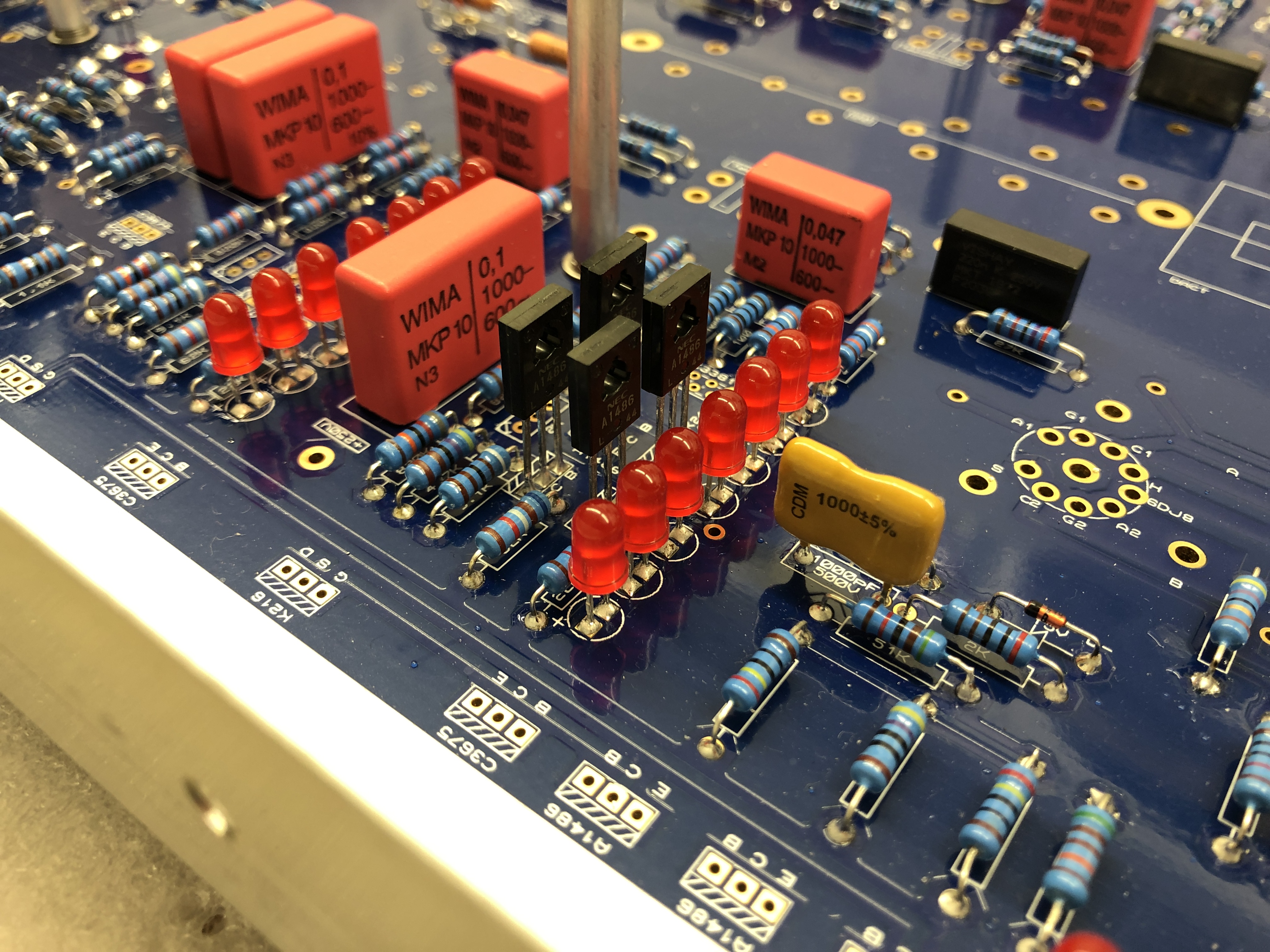
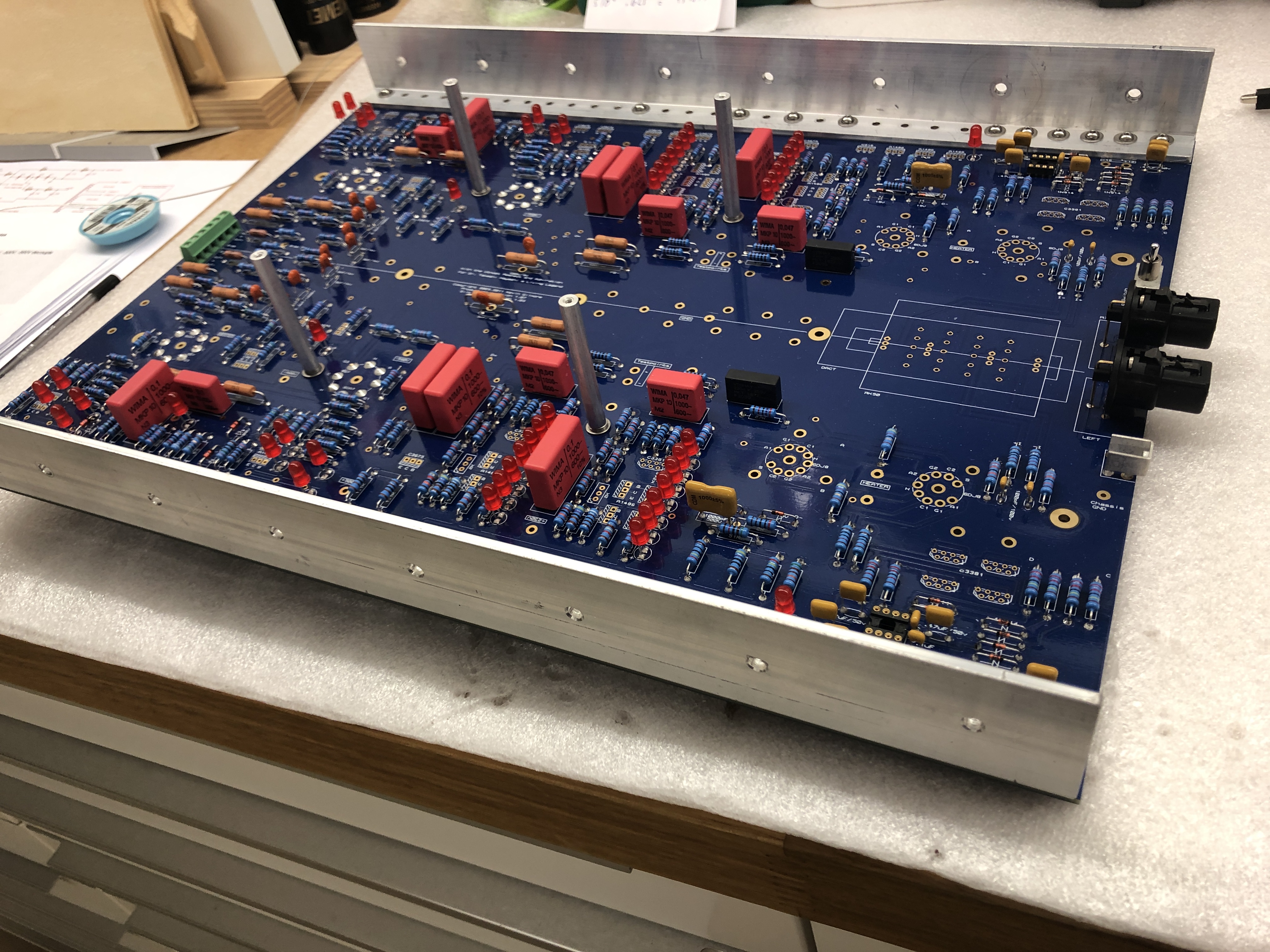
Phew, soldered some 50x LEDs... Checked the C3675 and A1468 for breakdown voltage. Will use the ones with the highest in the batteries. Are there any fakes of the C3381 and K246 and is there any special procedure for testing those? I mounted only 4 of the total 8 standoffs as the ones close to the front panel are in the way of the Stax connectors and the ones in the back are exactly where the Amphenol connectors are. 4 of them should be fine I think.
-
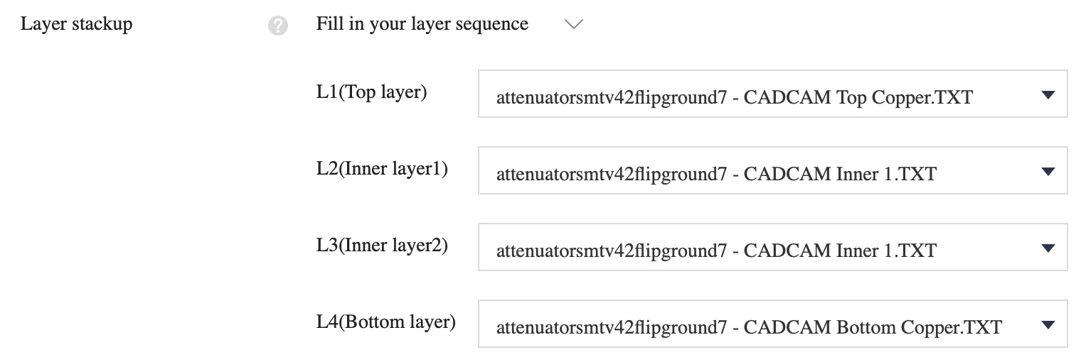
Preparing 4 layer board out of the 3 layer attenuatorsmtv42flipground7.zip as follows. Any other tips that I should take care for, like impedance controlled PCB? Going with thickness of 1.6mm and 1oz copper for the top and bottom layers and 0.5oz per each of both mid layers.
-
Anyone has balanced boards left, empty or populated? Please PM
-
Yeah, EL34. I have as well 4.5 and 1.5 amps per tube for the transformer secondaries. Sorry for typo, doing too many things at once right now 🙂
-
The EL84 would be even more with current draw at 4.5A or 9A per pair. But because each tube sits on its own wire and transformer winding it is 1.5A respectively 4.5A per 6CA7 or EL84 tube. So, Craig out of both wires given, would you for the umbilical go with the Cal Test 0.5mm2 20AWG 1KV 10A silicon wire or with the bulkwire.com PTFE 600VAC wire which I have 20AWG for the smaller tubes and 18AWG for the EL34s?
-
1KV and 10A rated silicon wire from Cal Test, 20AWG, 0.5mm2 conductor and 2.7mm OD for use with the heater AC wires: https://www.mouser.at/ProductDetail/510-CT2884-0-10 Compared to the PTFE wire it has double the thickness, 2.7mm vs. 1.37mm, both 20AWG, while 18AWG PTFE would be 1.67mm OD. Using two wires each 1KV makes it 2KV wire to wire. Using two 600V wires make it 1.2KV which is pretty much good to go for both the +/- 500VAC heater wires, as they are both insulated; correct me if I am wrong.
-
Thanks, Craig! I also thought wire to wire with 2x 600V should be ok. But would get the extra fiber glass insulation if I could find it.
-
I thought that the 600V PTFE wire was that everybody used, KG as well, no? That extra insulation would be nice to know what part no is it and where to get. I was randomly searching at Mouser but couldn't find anything suitable. Found here the Cal Test silicone wire 0.75mm 20AWG 10m black, pretty thick at 3.7mm OD. Looks pretty thick for that Amphenol connector, btw.
-
Any plans for a group buy? Any bare or assembled boards available for sale? Anyone has an updated BOM or are any of the parts unavailable by now?
-
That's the proper way of doing it in fully balanced equipment, chassis is separated from circuit ground and for shielding purposes only. Chassis goes then centrally to the star earth grounding (mostly in the PSU), where also circuit ground centrally may or may not go to (through a 10R resistor). 99% of the time Rane is not fully balanced but SE equipment using only balanced for I/O.
-
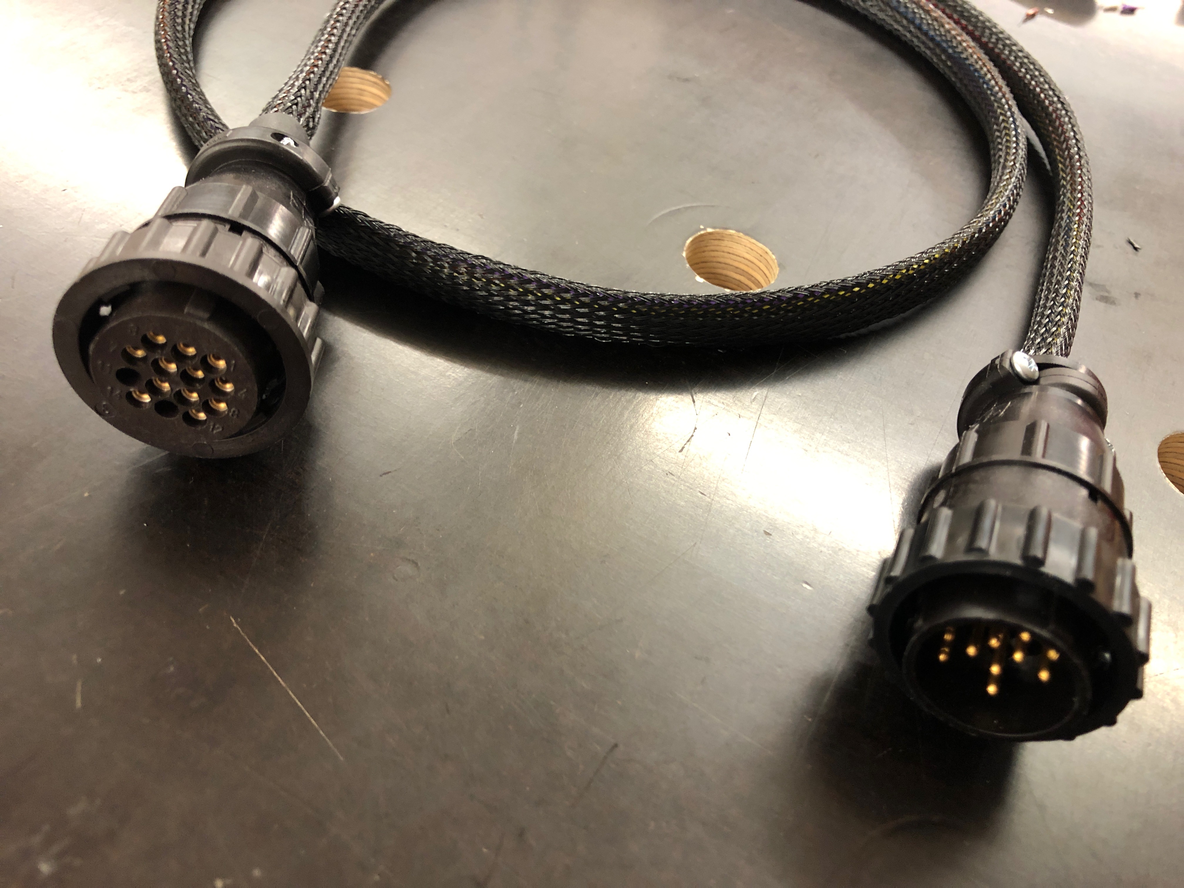
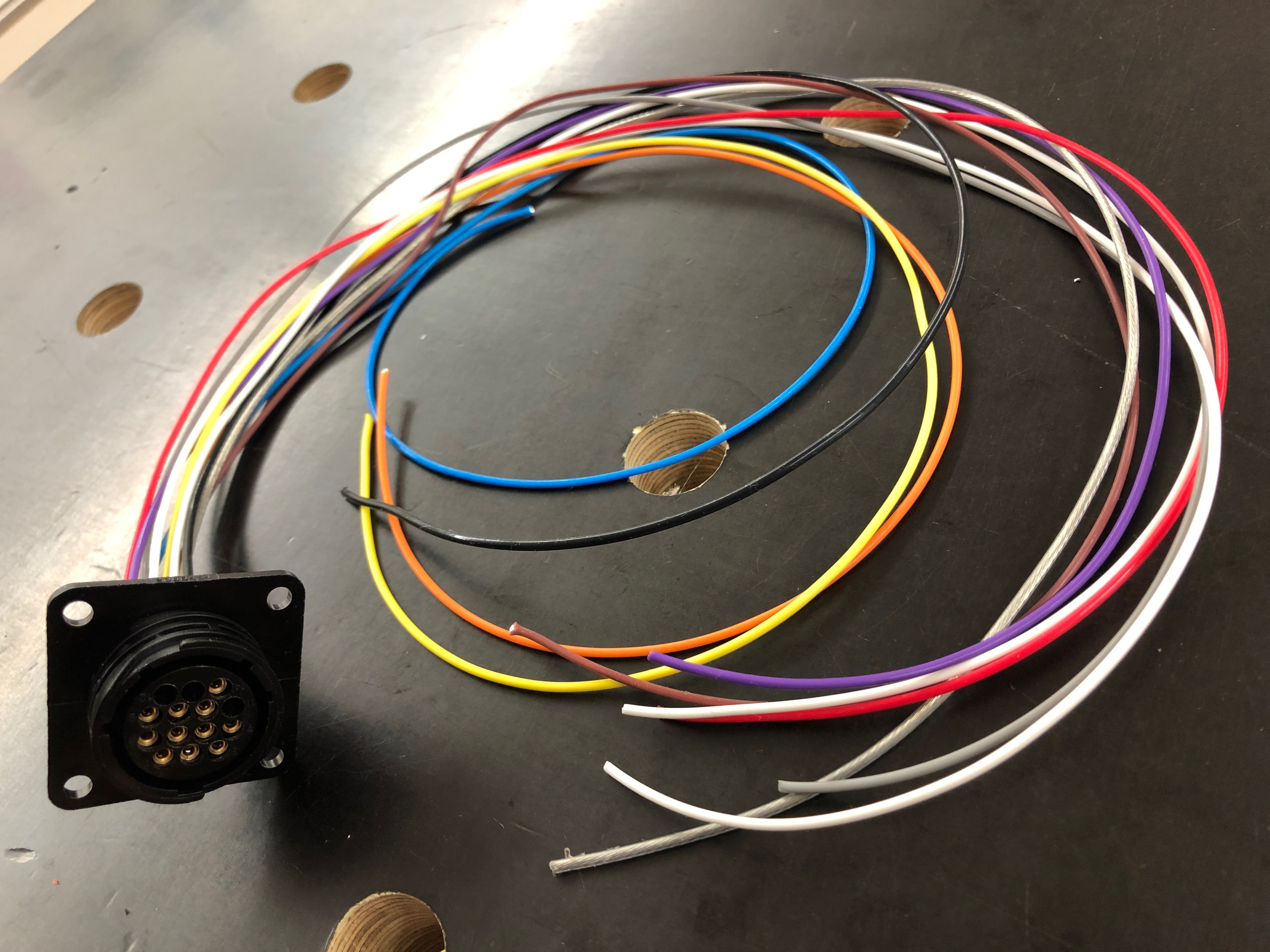
I am using silver plated stranded copper wire, PTFE insulation rated for 600VAC, mil-spec, wall thickness .25mm, temperature rating up to 200°C (392°F). Probably good enough for both wires against each other.
-
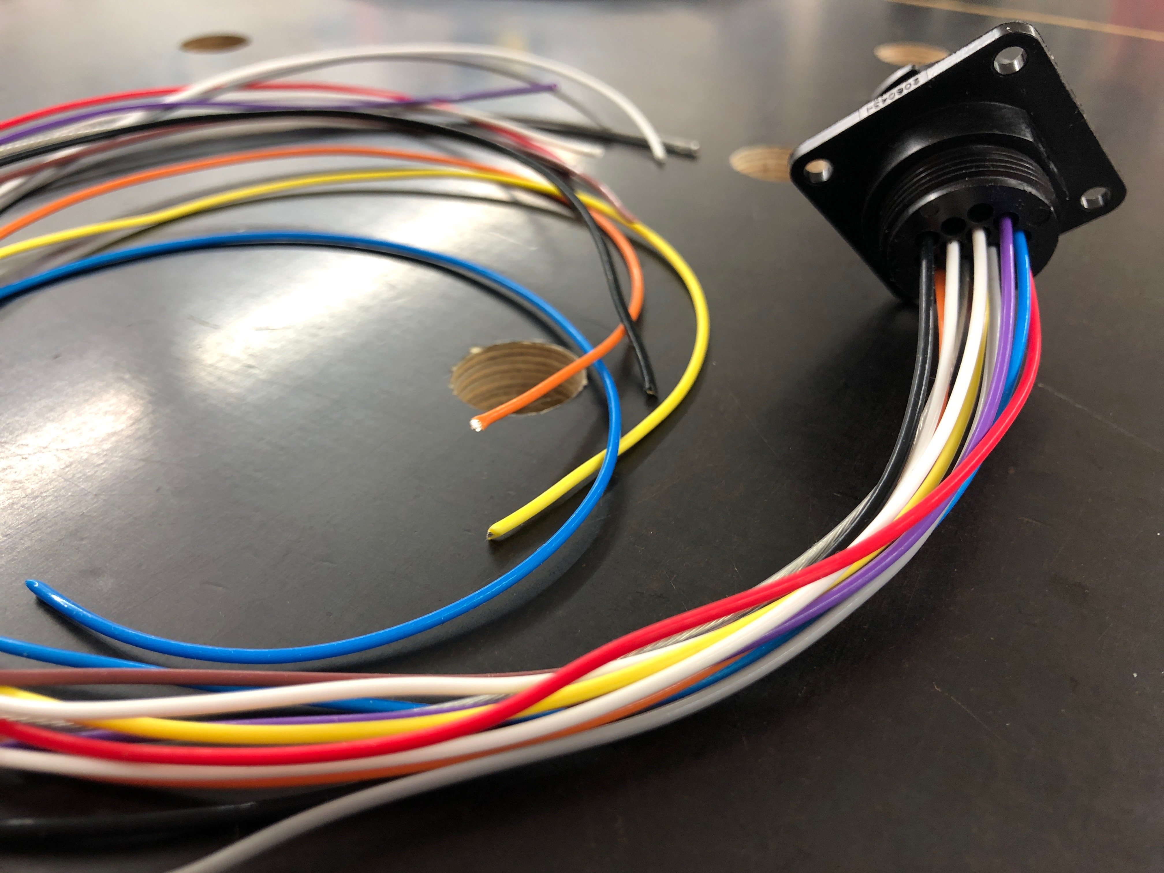
I am using this 15mm polyester sleeve from HellermannTyton for the cable above and considering using it for the T2 umbilicals as well. I don't have any additional sleeving inside the outer sleeve for special wires. I have twisted the 6.3V AC heater wires inside. Anything else I should take care for? This sleeve is very nice and is available in 25mm and 35mm as well.
-
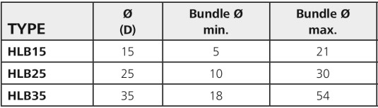
Yeah, they take a long time but are fun to make 🙂 I just completed the umbilical for the BHSE I am building (with original HeadAmp boards) and it took long as well despite using an AMP connector with crimp type pins. To be honest, I liked that connector much more than the Amphenol we use for the T2. It is like cutting wires, crimp pins on both sides and insert into the connector housing and voila. The pins are automatically isolated within the connector housing as well, so no fiddling with shrink tubing or soldering into the connector and the pins are available for different AWG sizes as well. A very nice system. Craig, do you have any part number for that special glass fiber insulation and how long are your umbilicals? I am planning for 90cm, 3ft.