MASantos
-
Posts
594 -
Joined
-
Last visited
Content Type
Profiles
Forums
Events
Everything posted by MASantos
-

and now for something completely different part 3
MASantos replied to kevin gilmore's topic in Do It Yourself
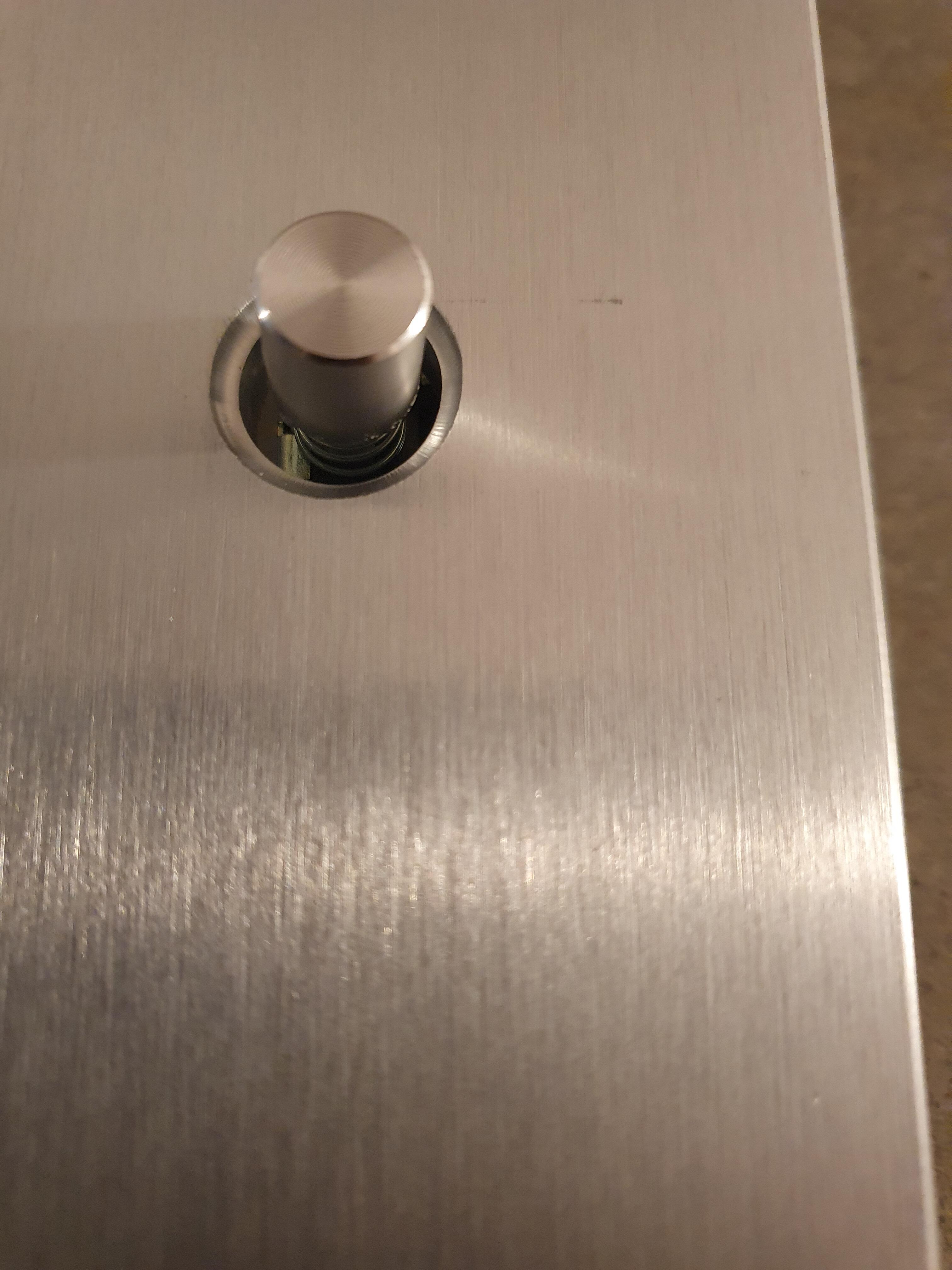
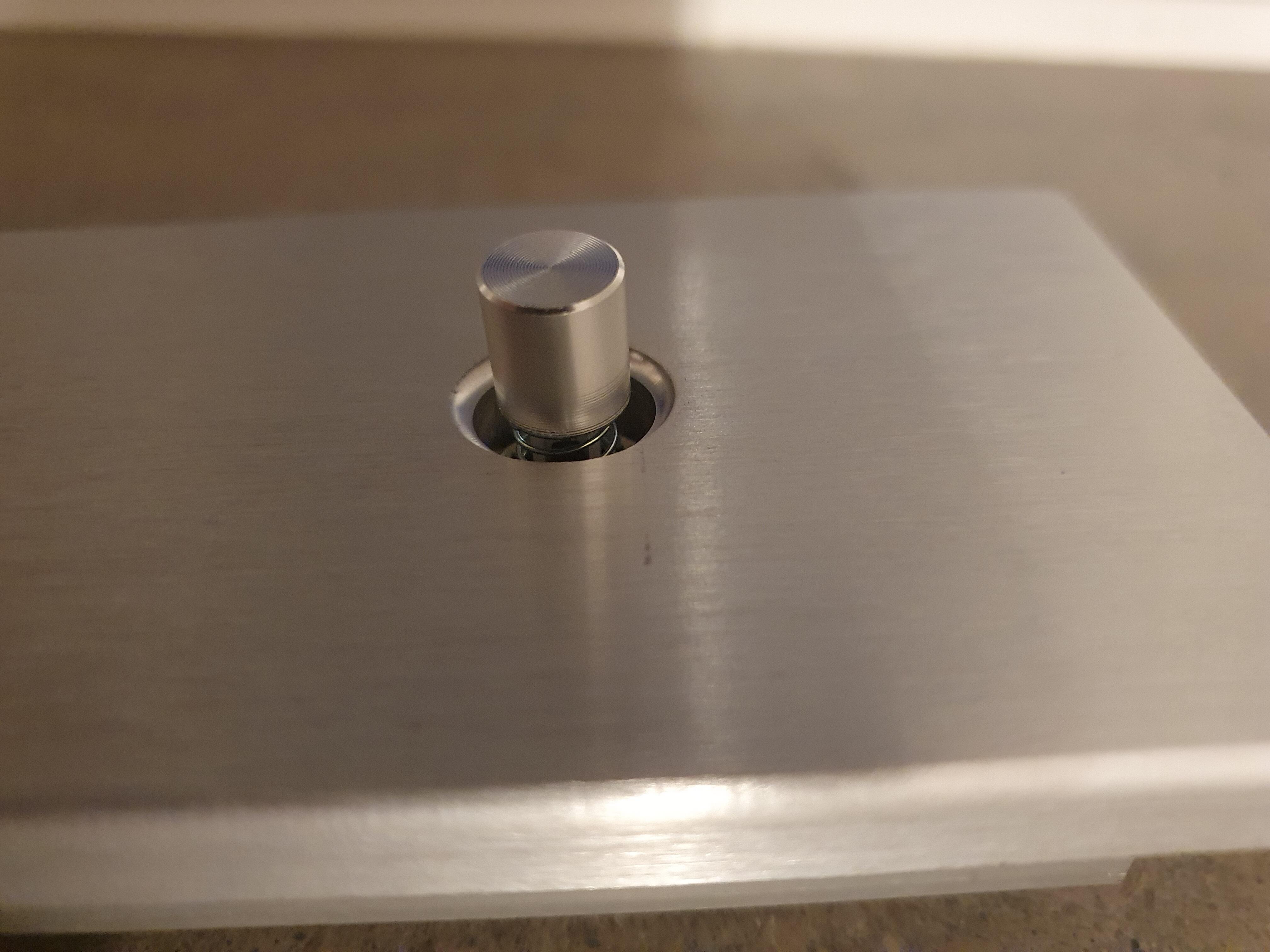
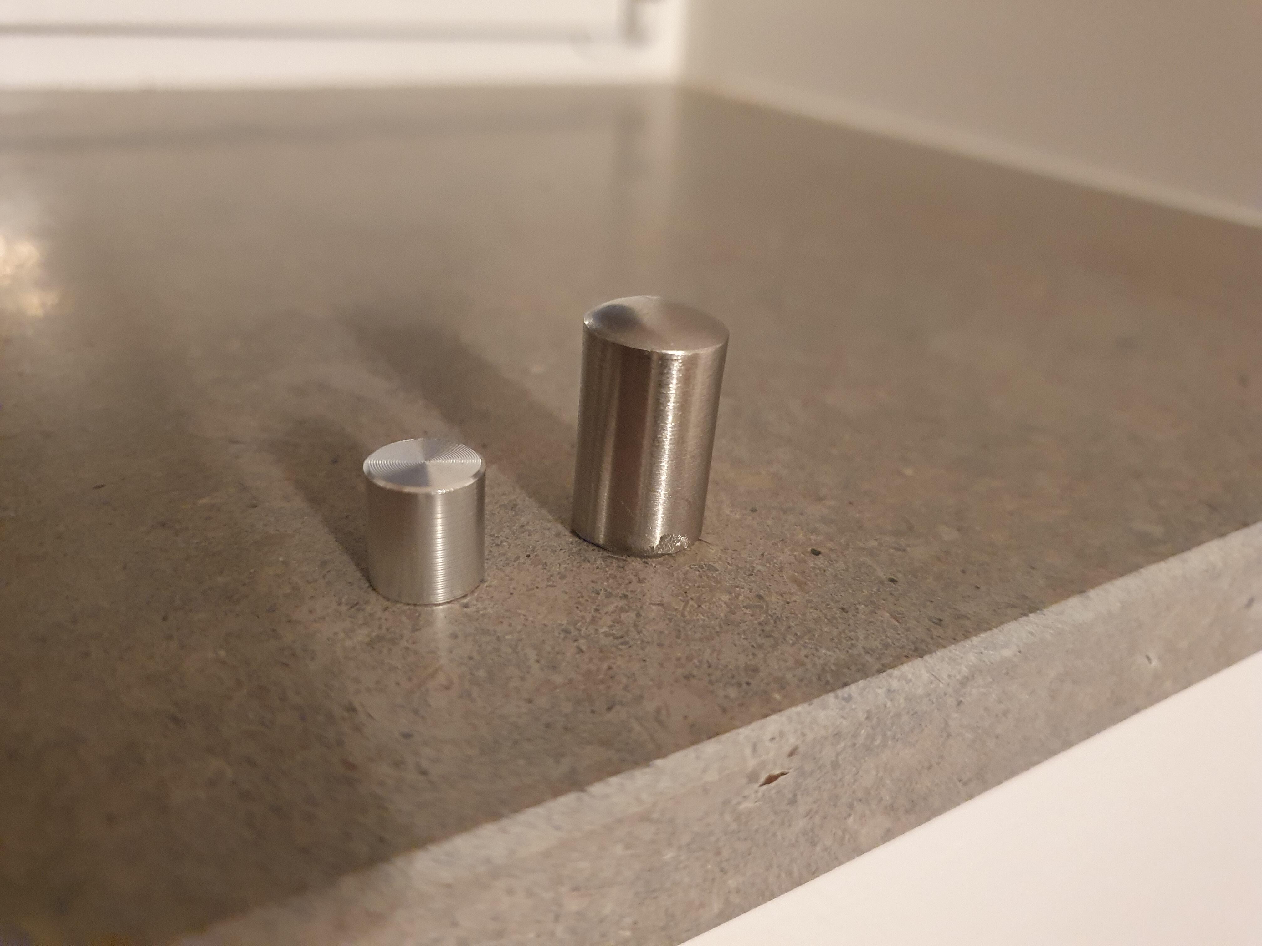
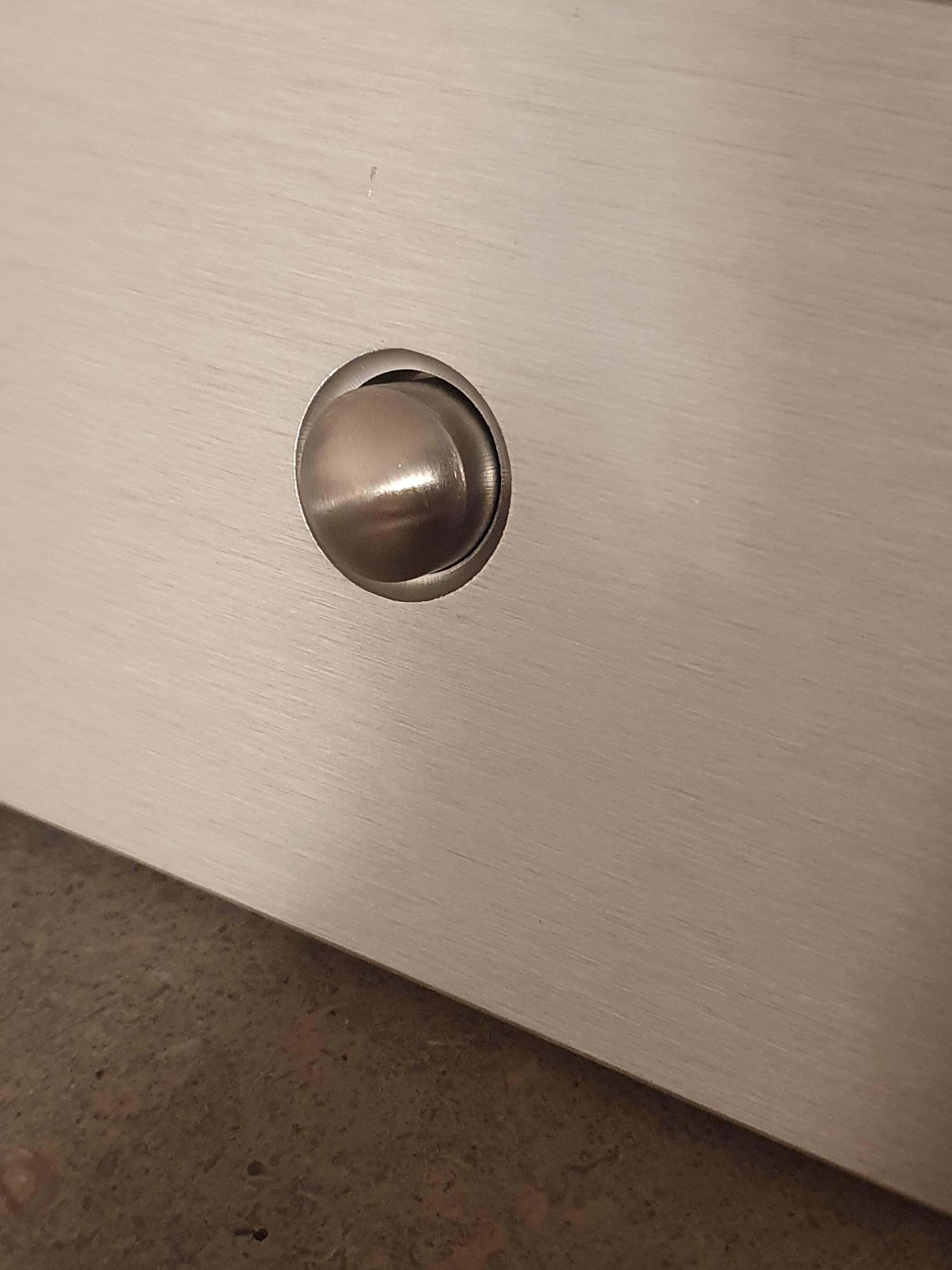
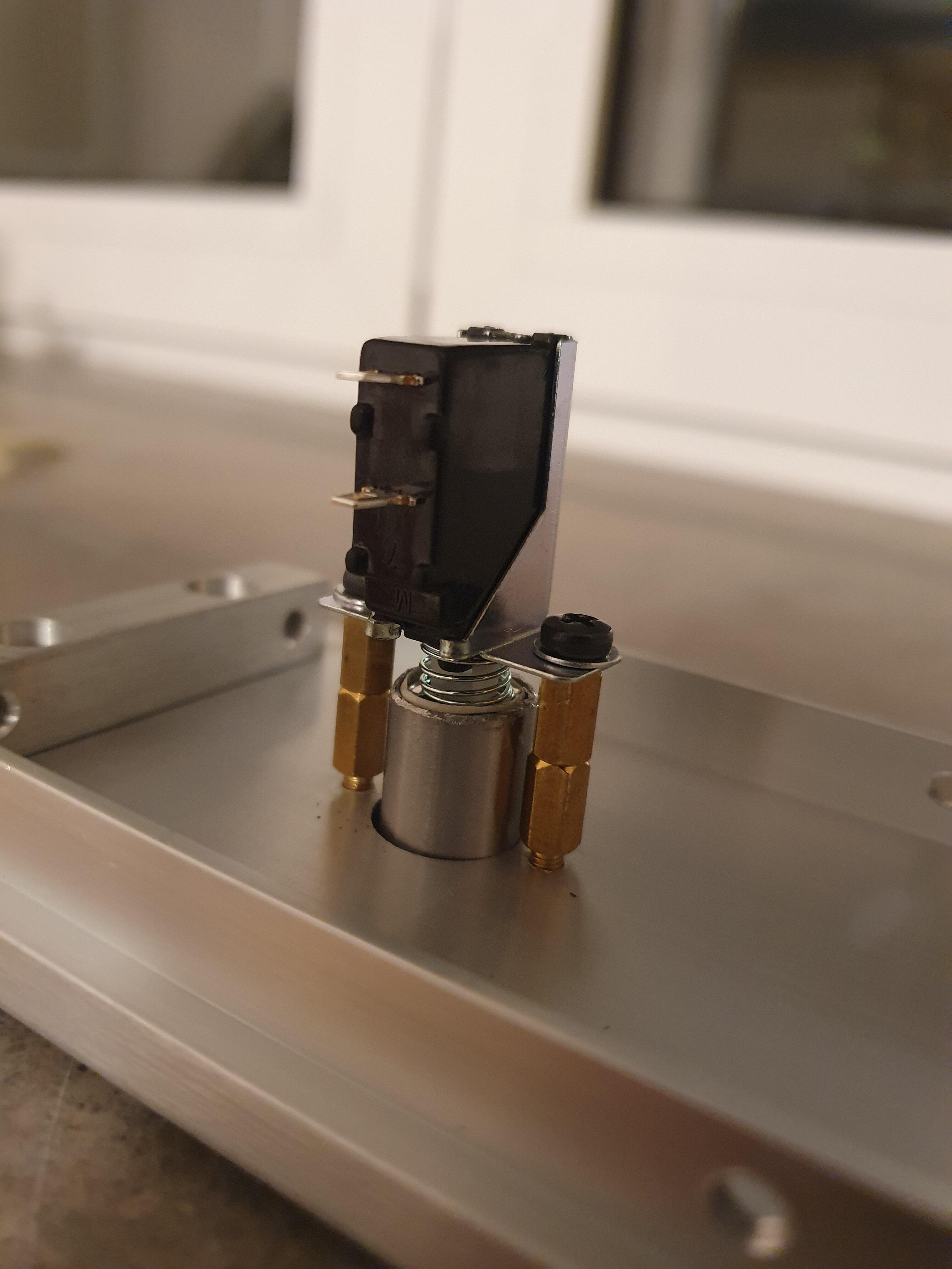
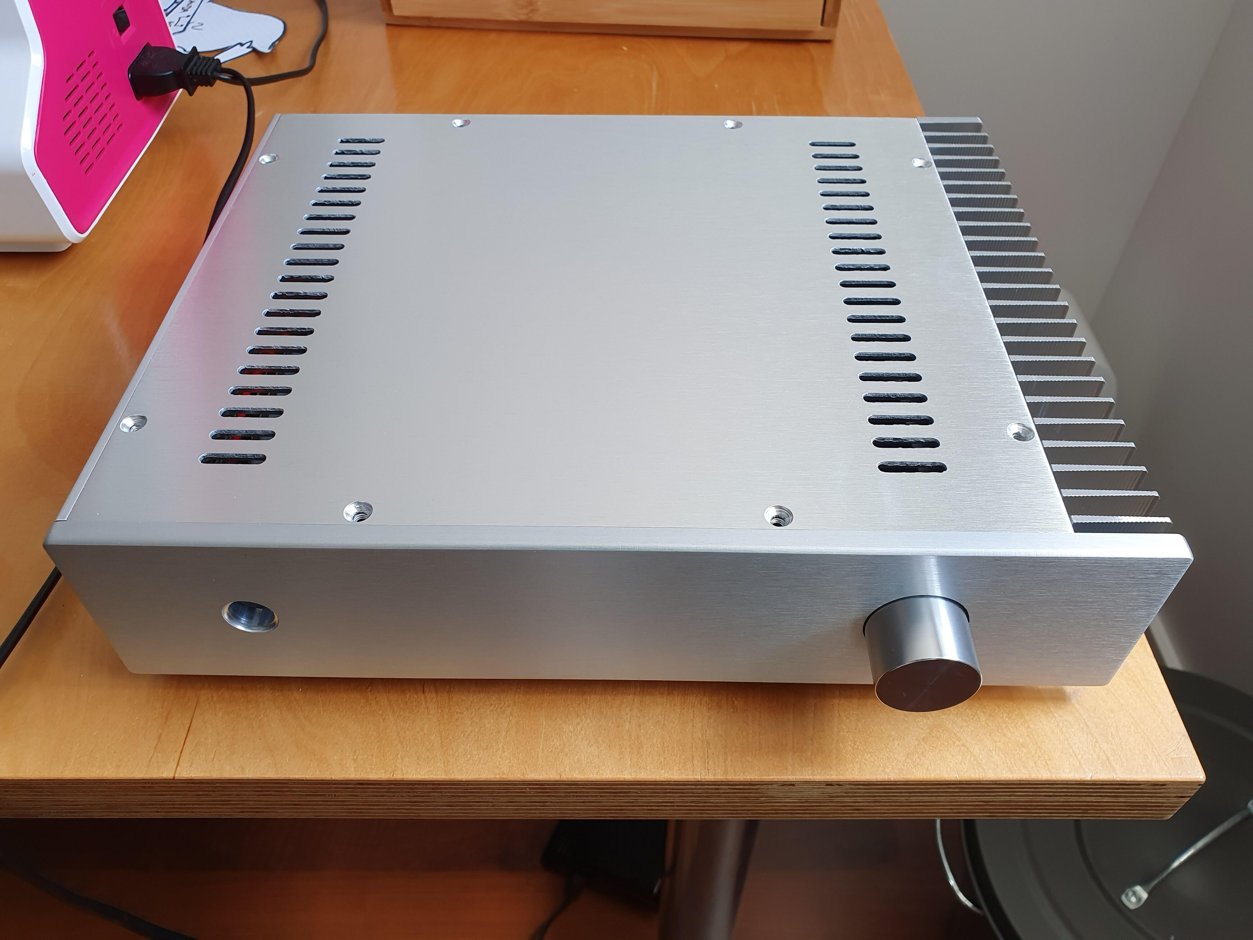
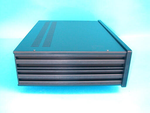
So when I got my case I got pretty upset with the looks of the power switch: So I search around the house for what could be used to improve this and found and unused aluminum kitchen drawer handle. Nice looks, hollow and easy to cut. A couple of minutes later:
-
and now for something completely different part 3
MASantos replied to kevin gilmore's topic in Do It Yourself
That's reassuring! Mouser forgot my opamps. They're in transit as we speak. Regarding biasing, I have about 190mV across the 1ohm output resistors, heatsink is around 40 C . What is the target for biasing? -
and now for something completely different part 3
MASantos replied to kevin gilmore's topic in Do It Yourself
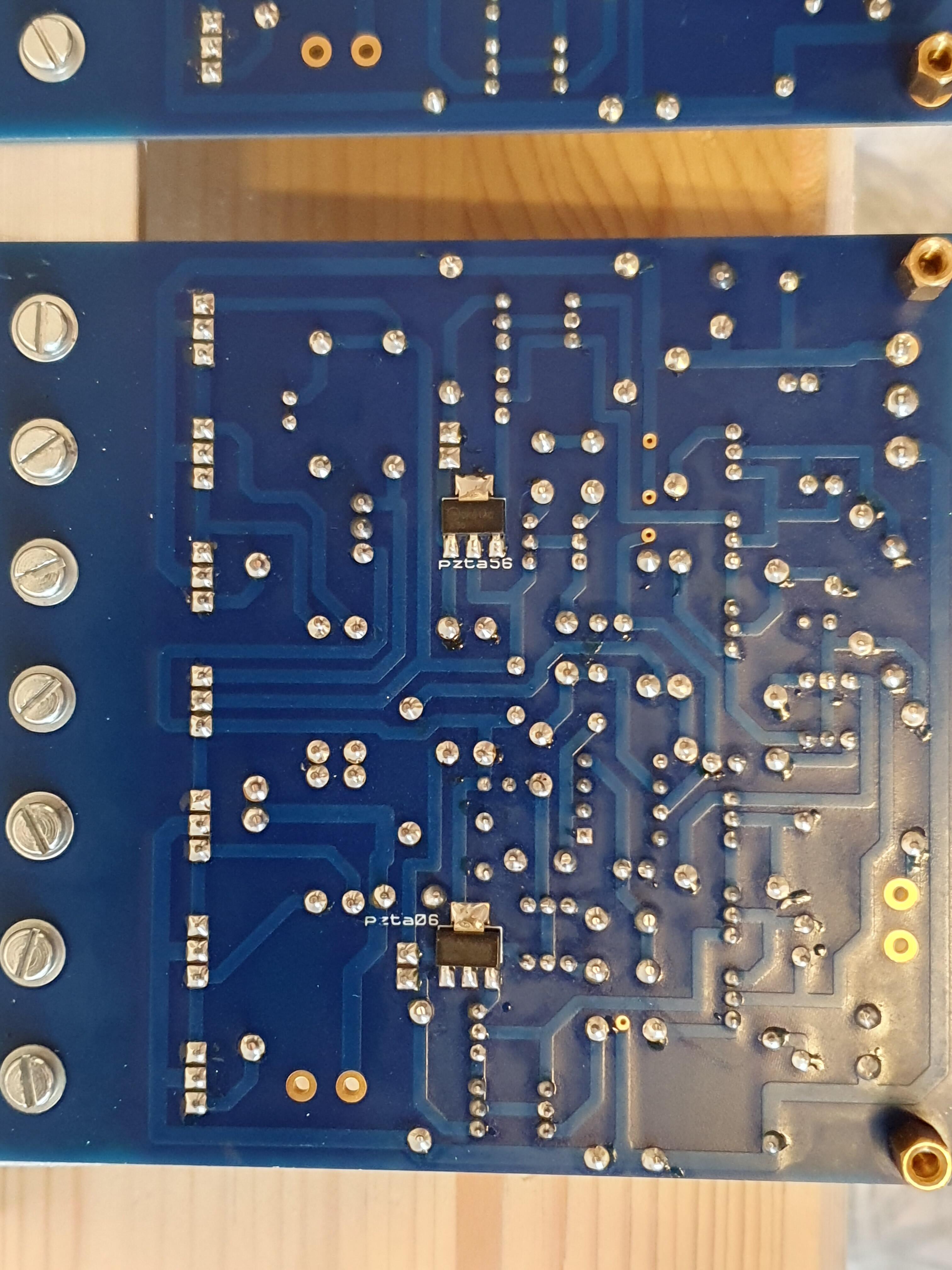
Did the diode across the board and found some discrepancies in the input pair. Replaced both critters and voila. Board is biasing normally, both LEDs are shining. 60mV of DC offset on both channels with inputs shorted. Will finish wiring inputs output while waiting for servo opamps. -
and now for something completely different part 3
MASantos replied to kevin gilmore's topic in Do It Yourself
Thanks for the tip.Will do it tomorrow and report back. -
and now for something completely different part 3
MASantos replied to kevin gilmore's topic in Do It Yourself
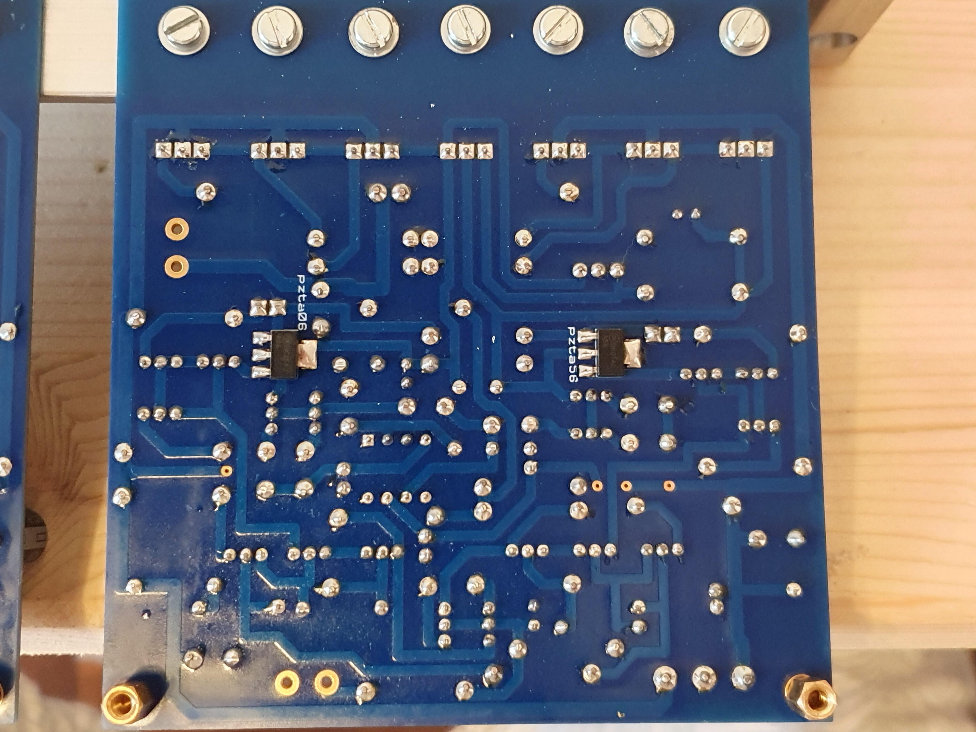
So I cleaned the boards once again and checked every transistor for orientation and location. Both boards match. 4 LEDs appear to be ok, similar voltage drop. I powered both boards and took some random VDC readings to ground. This is where things show that something is wrong. Most of the small critters have different readings. They all came from the same 100 unit strip bought from mouser. I guess I'll go ahead and start replacing them all. -
and now for something completely different part 3
MASantos replied to kevin gilmore's topic in Do It Yourself
I cleaned the flux with 96%alcohol and a tooth broth. There are only a few spots left. I did check the orientation and parts but will do it again later today after clearing my head from it. -
and now for something completely different part 3
MASantos replied to kevin gilmore's topic in Do It Yourself
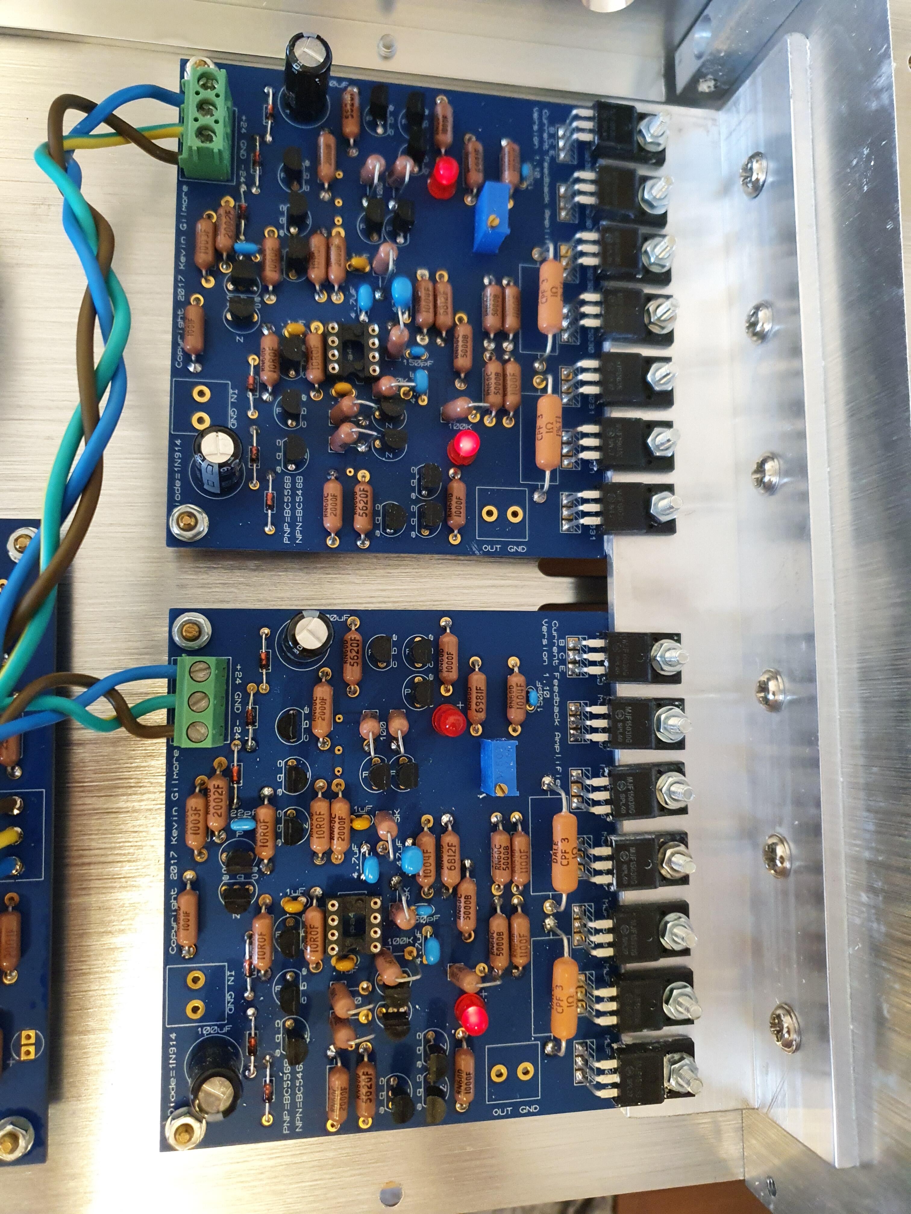
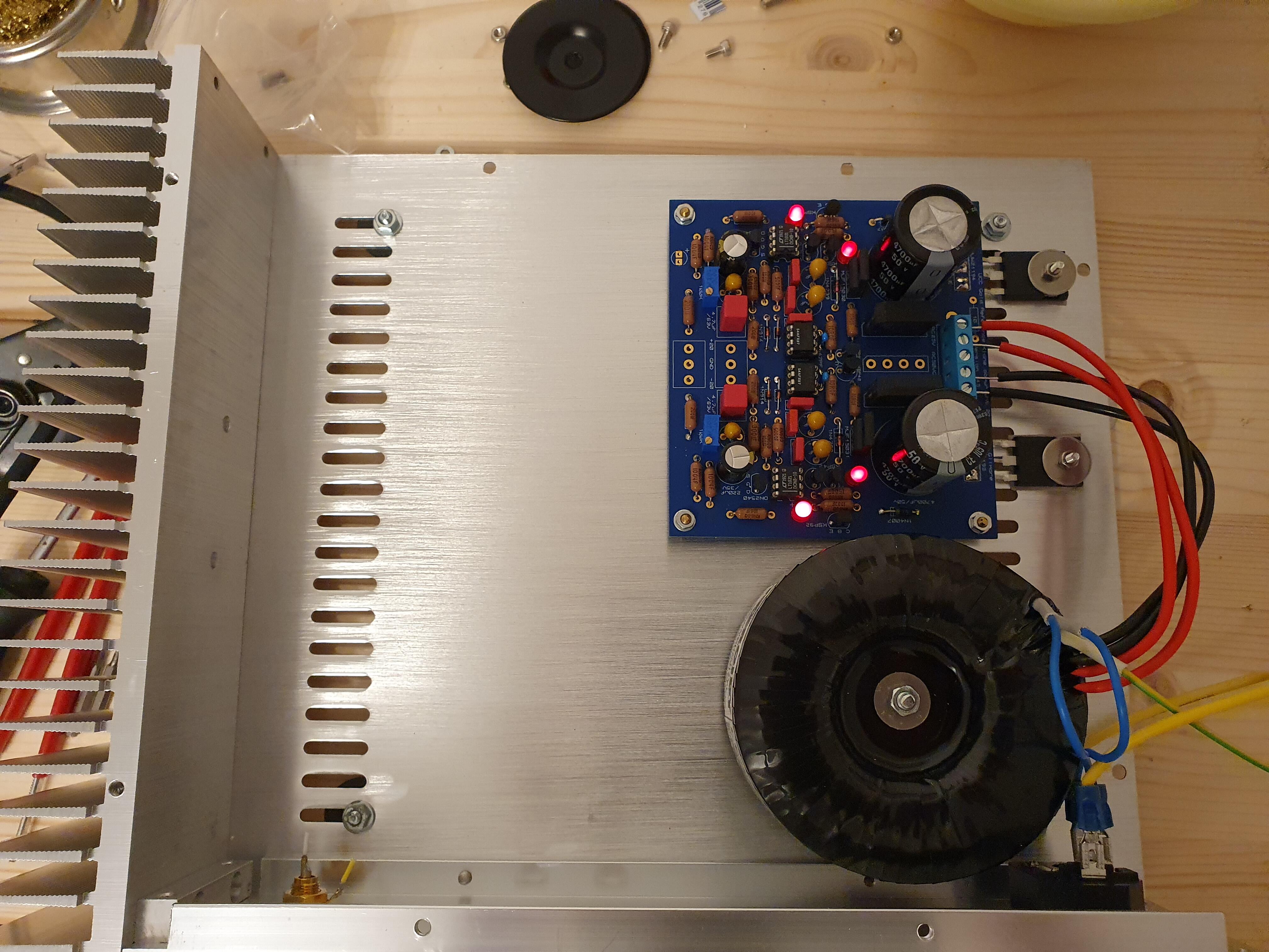
So I wired the amplifier board to the GRLV. One channel fires up ok. Both leds giving light, about 150mV across the output resistors 90mA offset without servo and input open. On the other channel I have one of the LED not lighting. No reading on output offset. all the LEDs test ok with a multimeter I diode check and emit a small light. On the mjf15030, the output resistor reads 30mv across. On the 15031 nothing across the output resistor. I don't see any solder bridges. Should I start replacing stuff?
-
goldenreference low voltage power supply
MASantos replied to kevin gilmore's topic in Do It Yourself
Apparently mouser forgot to send me the opa134 needed so I plugged a pair of opa445 for the CFA servo. No smoke. Voltages are +25.02 and -25.11 I didn't match any of the LEDs or resistors so this seems pretty good to me and probably won't make a difference in real life.
-
and now for something completely different part 3
MASantos replied to kevin gilmore's topic in Do It Yourself
I had the under switch in my power amp, but this one wont have feet high enough to reach under. I'm ordering a latching anti vandal switch and will be using a 4 pin xlr even though the amp is single ended. I already have my hd650 with a balanced connector so I wont have a need for adapter cables. -
and now for something completely different part 3
MASantos replied to kevin gilmore's topic in Do It Yourself
Looks great!! I got my case today. The power switch is rubbish and I'll try to get an illuminated pushbutton with European approval that fits the hole. Does anyone know of nice looking 1/4 Jacks other than neutrik?
-
goldenreference low voltage power supply
MASantos replied to kevin gilmore's topic in Do It Yourself
Thanks. -
goldenreference low voltage power supply
MASantos replied to kevin gilmore's topic in Do It Yourself
Ok. My case in in customs, might as well wait a couple more days and test it in place with output thingies in the heatsink. -
goldenreference low voltage power supply
MASantos replied to kevin gilmore's topic in Do It Yourself
Received my transformer today from toroidy.pl. As always great quality. Any special startup procedures I should be looking for? Should I power on without voltage references, opamps or output transistors first? -
WIP: Angle bracket for my cfa amp.
-
and now for something completely different part 3
MASantos replied to kevin gilmore's topic in Do It Yourself
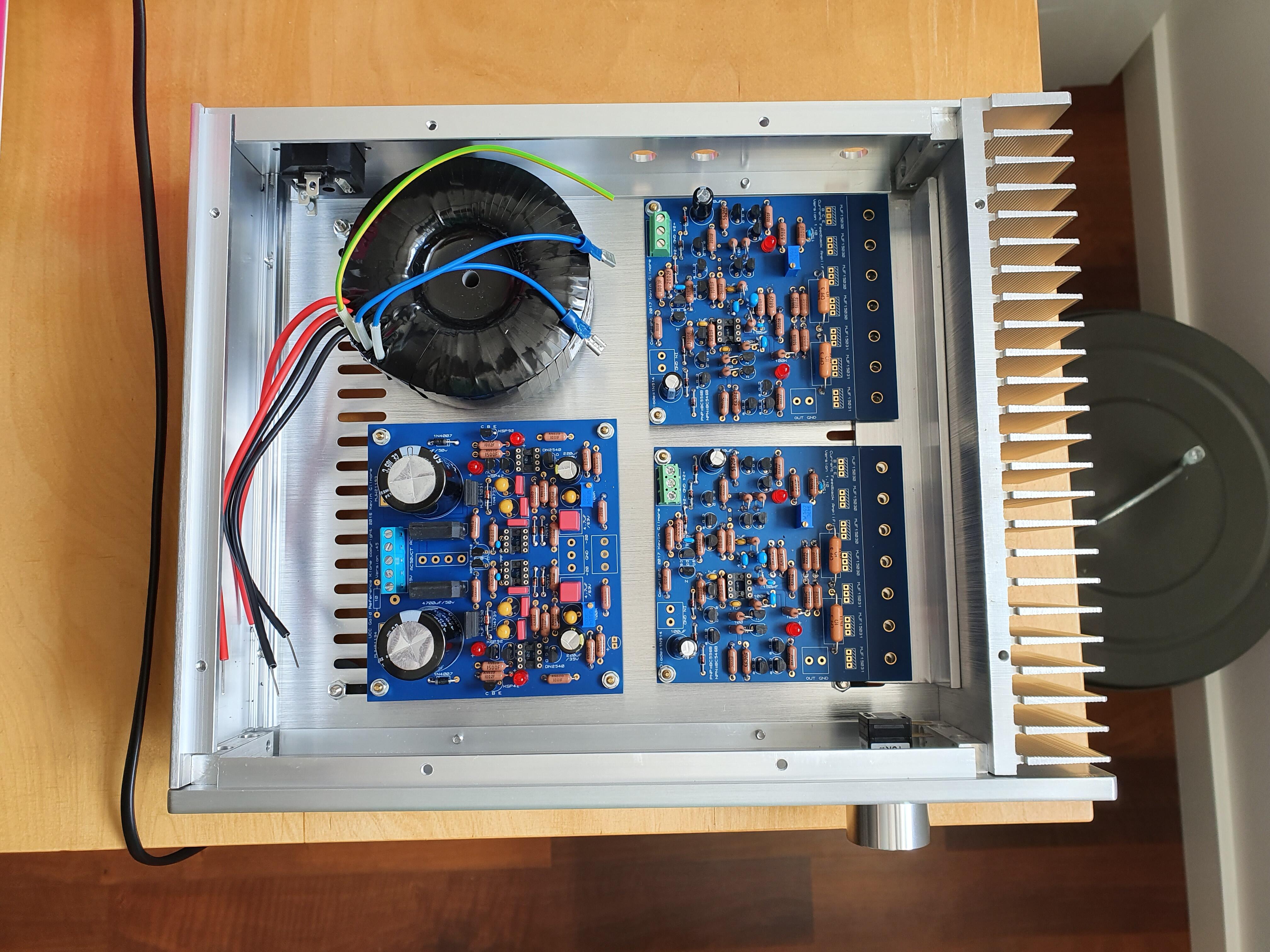
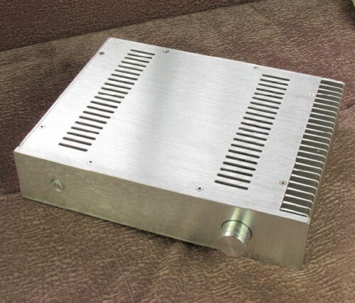
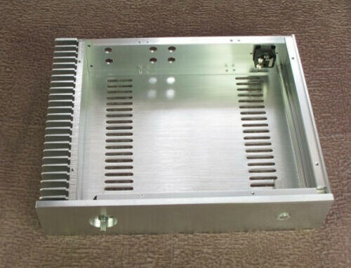
I settled on this case: width 320, height 70, depth 248, plenty of space for a single ended cfa and I might even be able to fit a coilcraft COMOCO choke filter (comon and differential filter in the same choke.) Transformer will be a 100VA from toroidy.pl, used them in other projects and quality is top notch. Now on to find a suitable 10K volume control. Would like something a little better than a RK27. stepped attenuator or a relay based one. Any ideas that don't break the bank?
-
goldenreference low voltage power supply
MASantos replied to kevin gilmore's topic in Do It Yourself
I've read a few parts of this thread but would like to confirm the following: For a 24VDC output to power 2CFA boards I should use a 22-24VAC 50-60VA transformer right? How important is led and resistor matching? Do I really need 5 decimals of precision in the output voltages? -
I am building a single chassis single ended version. I thought about something like this: It could be a small cube about 14-16 cm sides. everything bolting to the heatsinks. I would have to make it myself though. Commercially I found some aceptable options: https://www.audiophonics.fr/en/aluminium-boxes-cases/diy-case-amplifier-100-aluminium-271x240x90mm-p-9499.html
-
What case did you get for yours? Looking around for options but I either find too big or too small
-
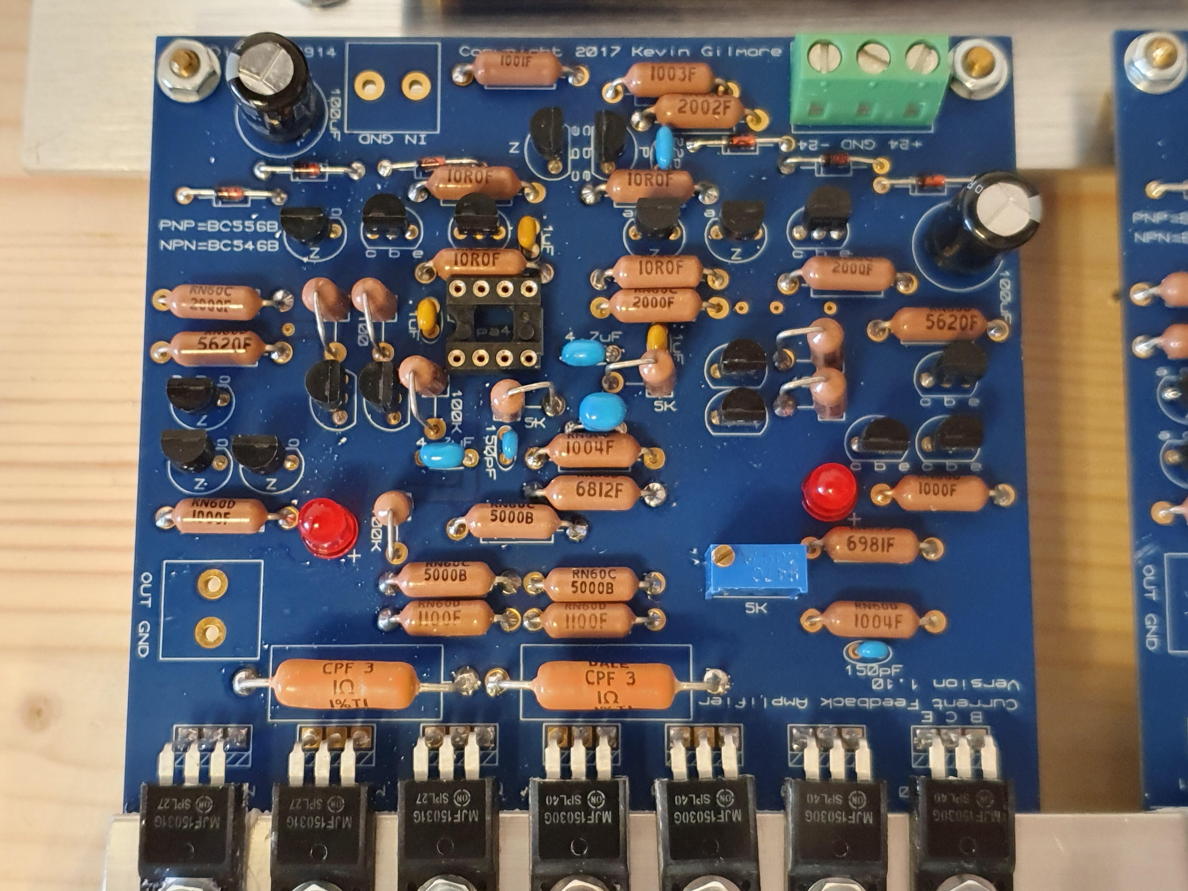
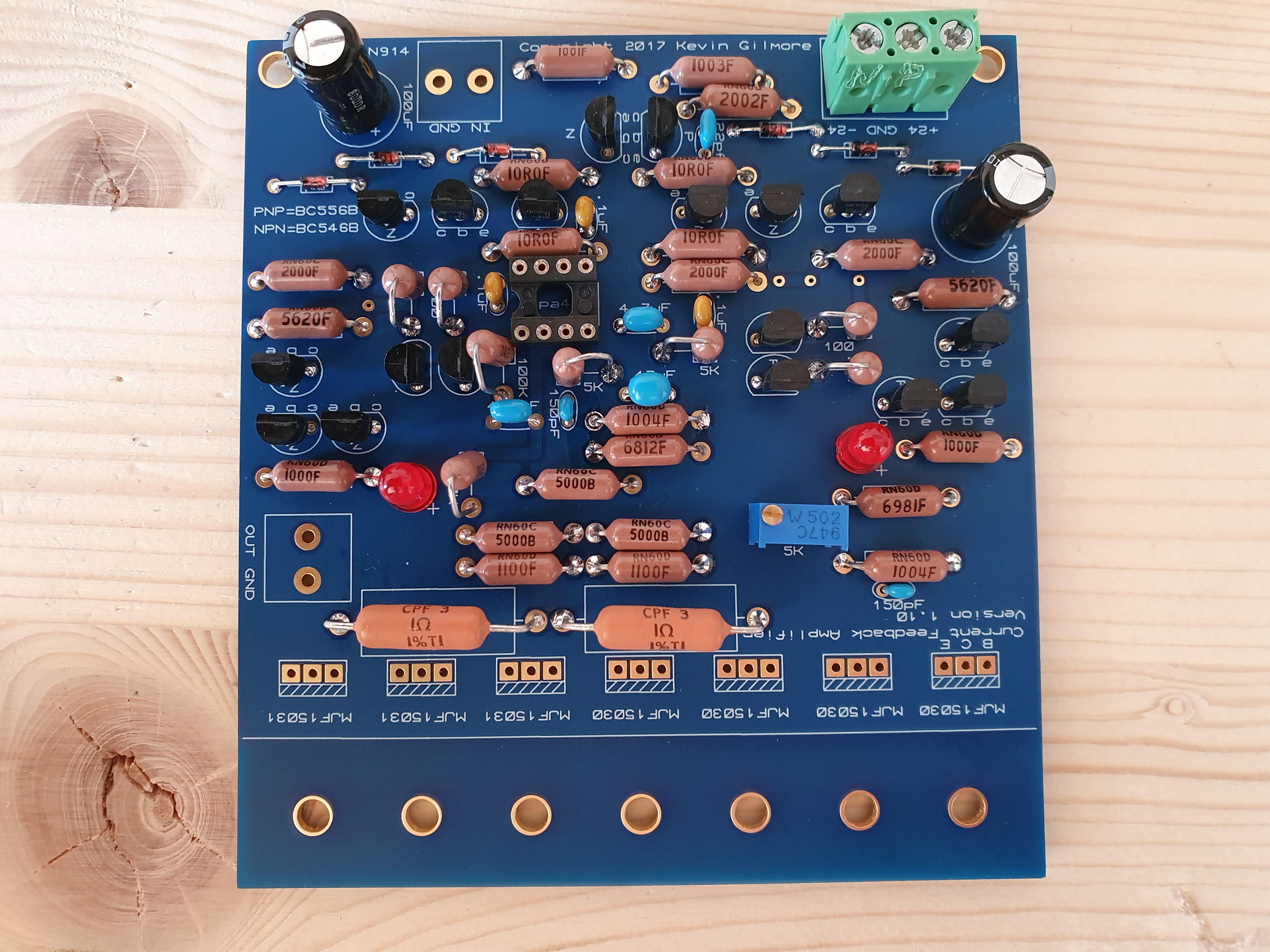
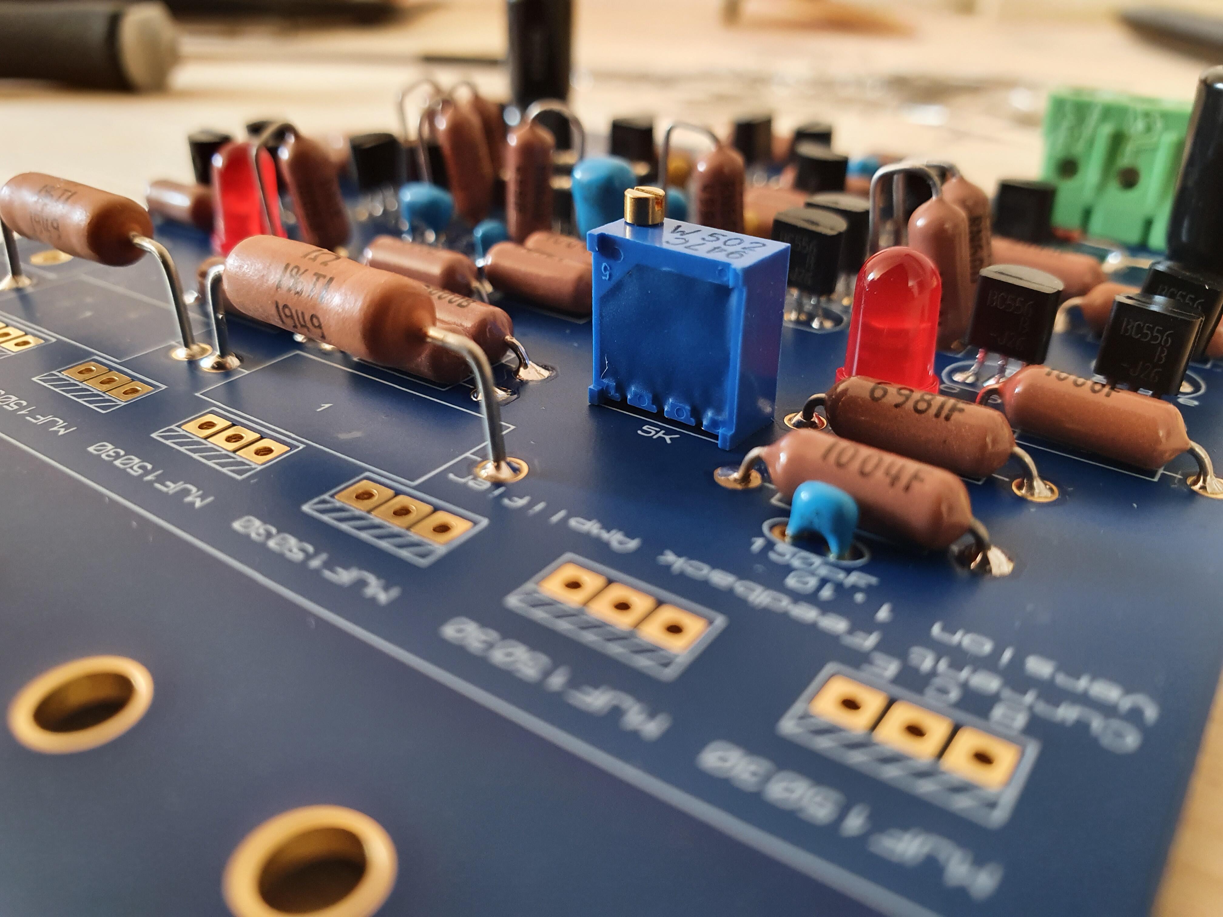
One CFA board done. Small BJTs were incredibly close matched in the tape reel. A few decimals of mA between them. RN60 resistors, and 3W CMF at the outputs.
-
I started matching transistors today for my cfa build but quickly started scratching my head. I'm using Amb.org bjt matching circuit with a 110K resistor for the MJF1530/1531. I got between 9 and 15 mA for the 1530's and ~30mA range for the 1531's. Shouldn't I get closer readings between N and P devices?
-
The Never Ending Search for a Music Server
MASantos replied to n_maher's topic in Home Source Components
You can also check the bluesound devices. One of the best interfaces in the market IMO and they have a unit with built in storage. I've had the Node for some years now to use with LAN stored music and tidal and it is reliable, fast and easy to use. I had tidal until recently but changed to spotify family plan. Easier UI, controls the amplifier and wifi speakers around the house directly and for casual listening I can't hear the difference between spotify and tidal. -
and now for something completely different part 3
MASantos replied to kevin gilmore's topic in Do It Yourself
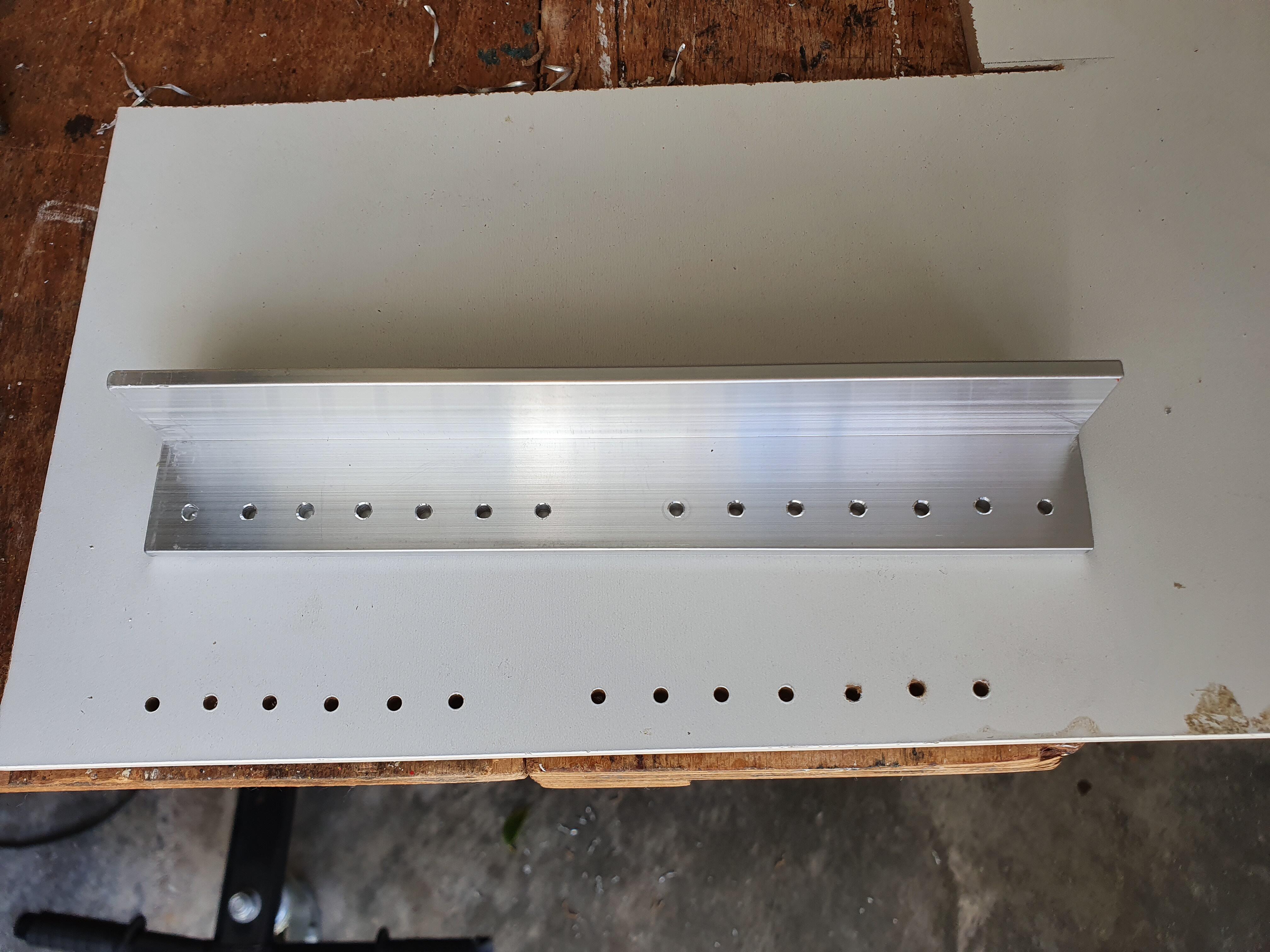
I plan to use this side panel, it is 10mm thick and is able to cope with a few watts. Should be similar to a bottom panel some others have used I believe.
-
and now for something completely different part 3
MASantos replied to kevin gilmore's topic in Do It Yourself
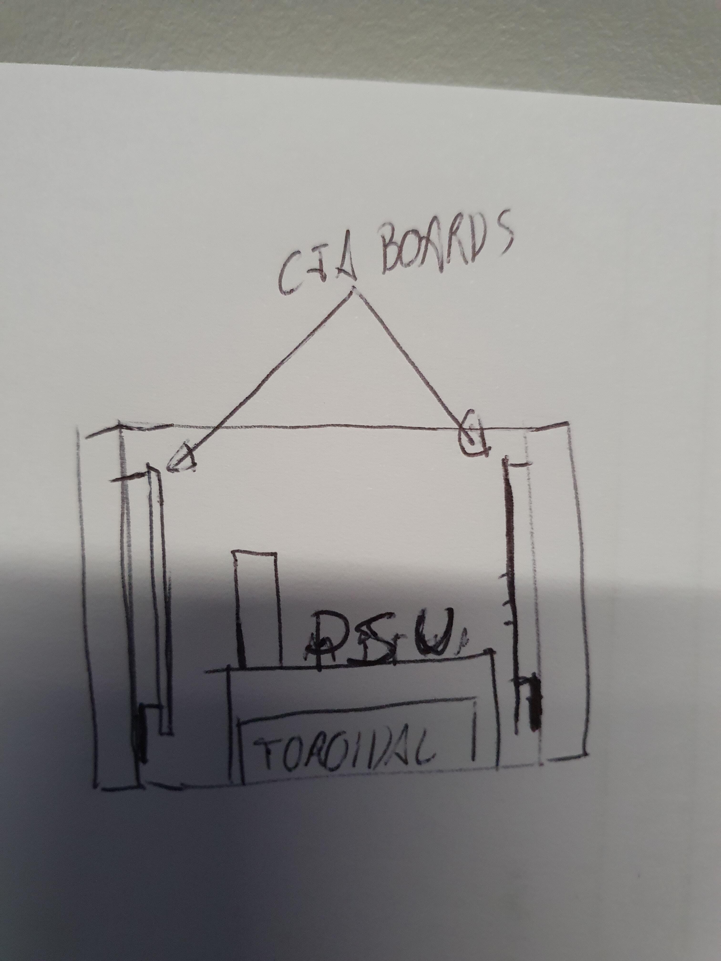
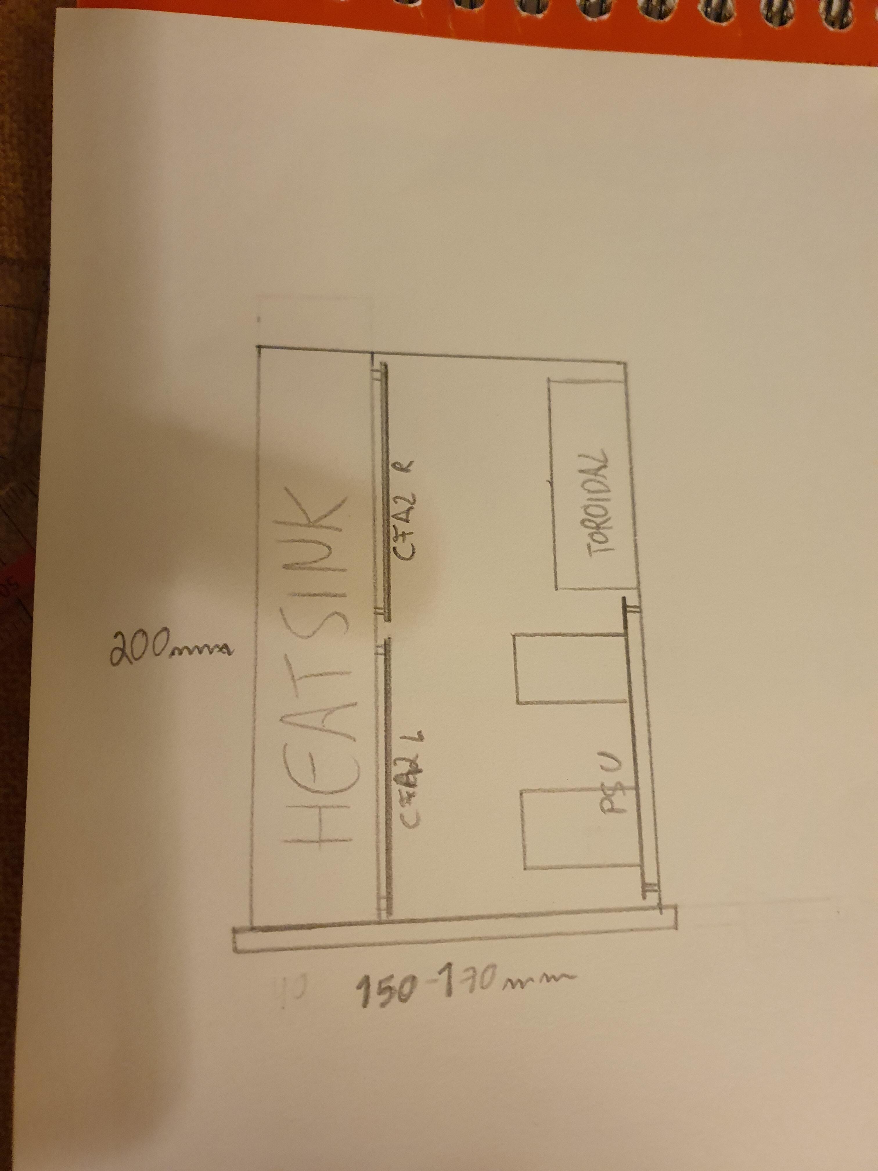
So I just ordered some of the parts to start building my single ended CFA and some decisions need to be made before I continue for which I ask your help: 1. KG recommends +-24V, is there any real benefit in going up to 30V for "regular" cans such as HD650. I do not see myself buying a pair of orthos in the near future although I would like to try them at some point. I am looking to build a single chassis in a somewhat small footprint so having to deal with the extra heat might be a problem. 2. What heatsink size would you recommend for this? I am thinking of placing both boards on a 200x120x40 heatsink from modushop to make a single heatsink enclosure like the one I sketched. 3. Any suggestions regarding stepped attenuators or volume pots that don't break the bank? I'd like some better quality than a RK27... I'll probably have some more doubts before I finish so you'll have to bear with me on this one.
-
goldenreference low voltage power supply
MASantos replied to kevin gilmore's topic in Do It Yourself
Starting to gather parts for a GRLV and found a pair of 4700uf 63V nichicon UKW capacitors. They are leaded not snap in. Any issue with using these in the PSU? Comparing to regular snap in caps I get higher ripple current but rated only for 2000h vs 3000h. -
No offset between positive and negative sides on the same channel!! Cool!!