Leaderboard
-
Grahame
High Rollers30Points16723Posts -
Voltron
High Rollers26Points34514Posts -
Hopstretch
High Rollers12Points16779Posts -
naamanf
High Rollers10Points6660Posts


Popular Content
Showing content with the highest reputation on 02/24/19 in Posts
-
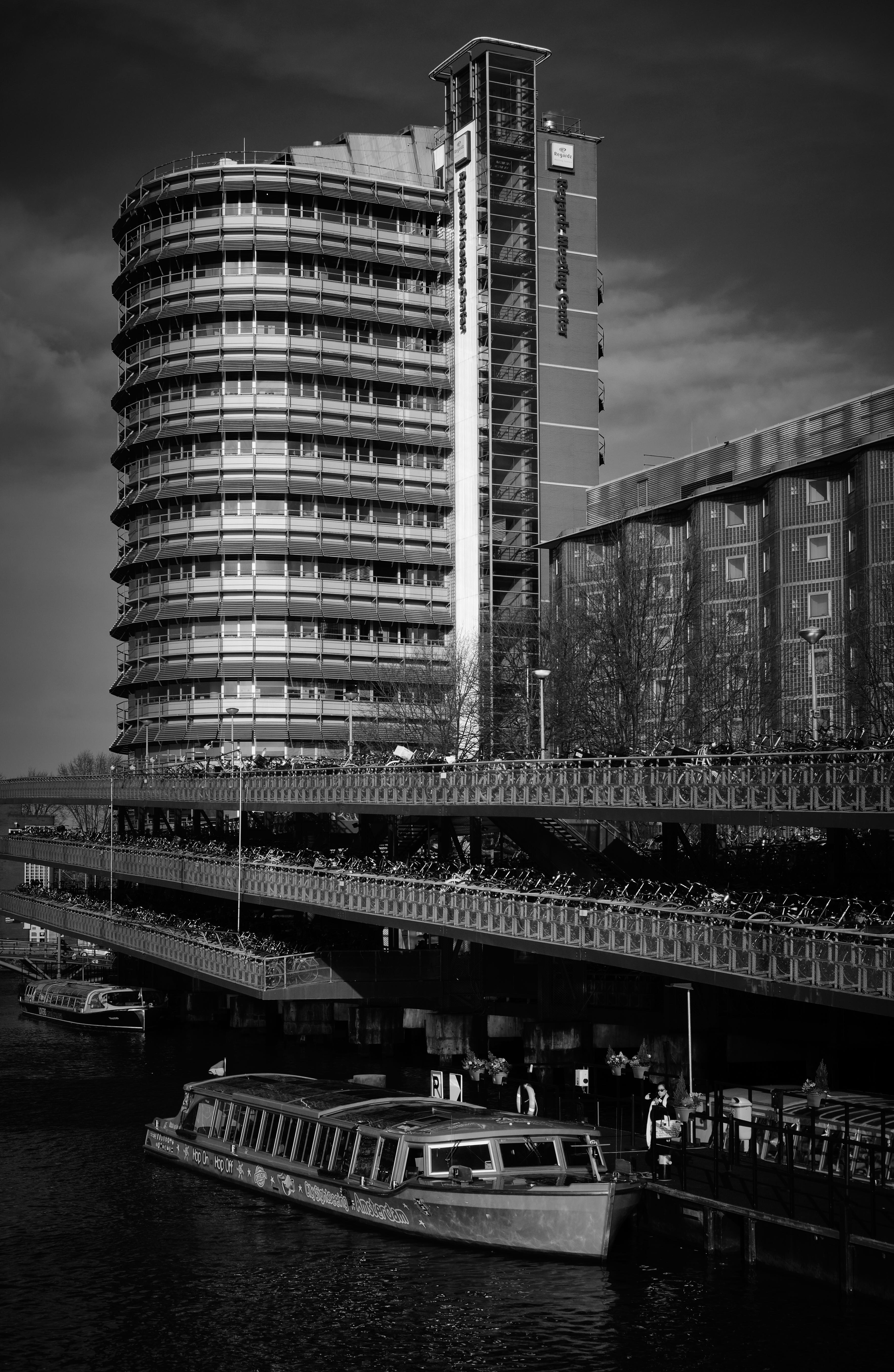
As I may have helped pause this thread, a few shots from a recent Amsterdam trip to unpause. First two iPhone XR. Rest Fujifilm X-Pro2 with XF 35mm f/2.
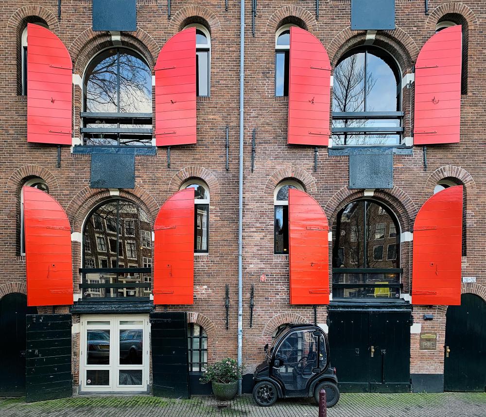


 2 points
 -
2 pointsPhew. I need to maintain a solid role model/mentor for my retirement goals.2 points
-
1 pointNibbles to go with Sri Lankan afternoon high tea Think Sugar, five ways.
 1 point
 -
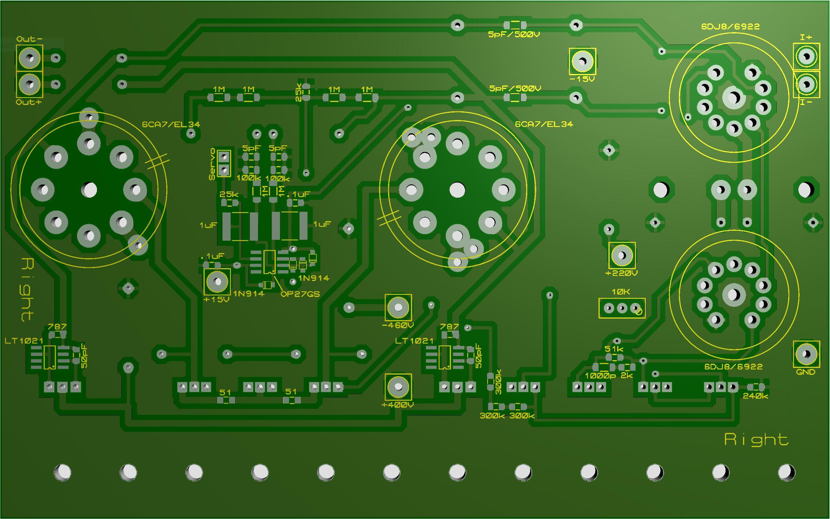
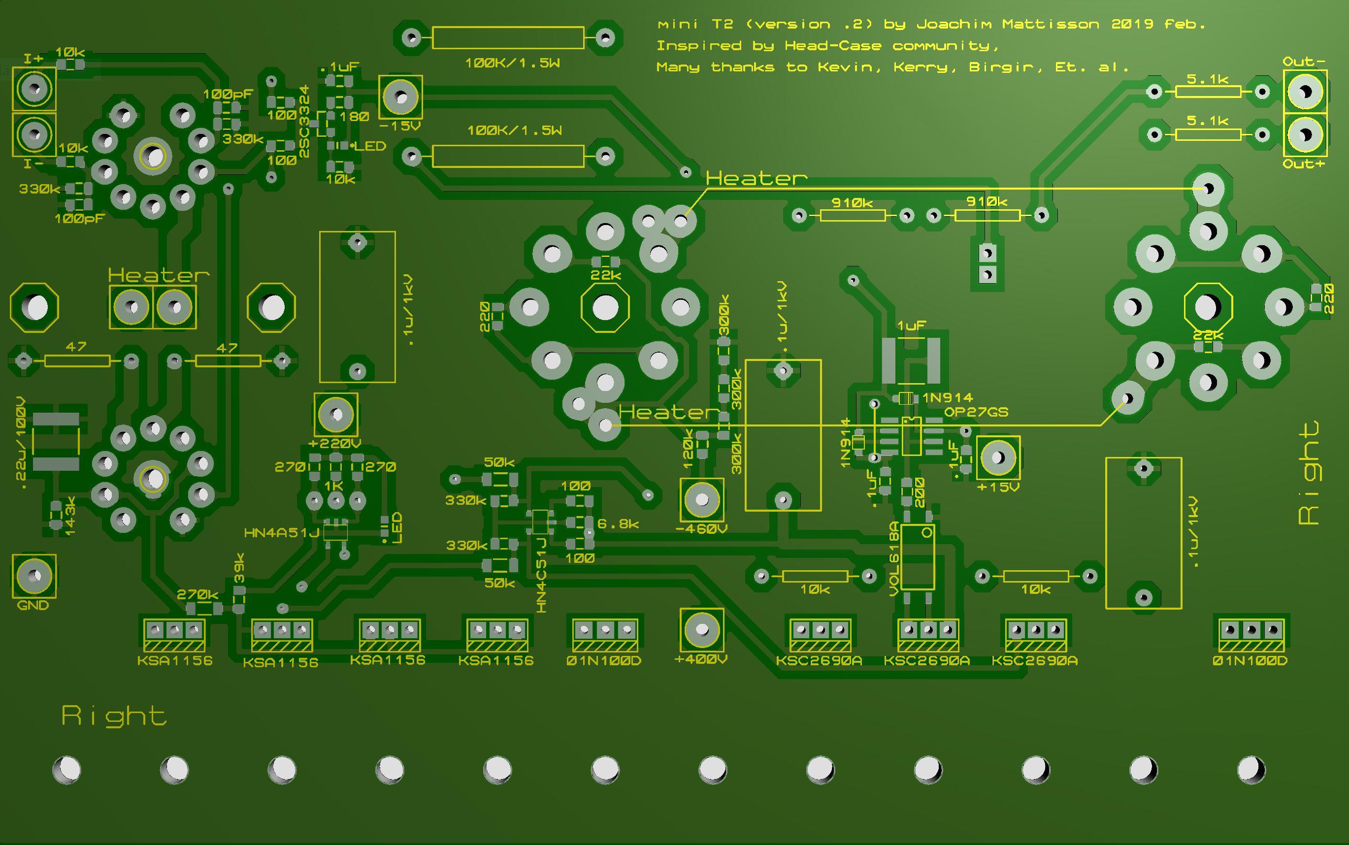
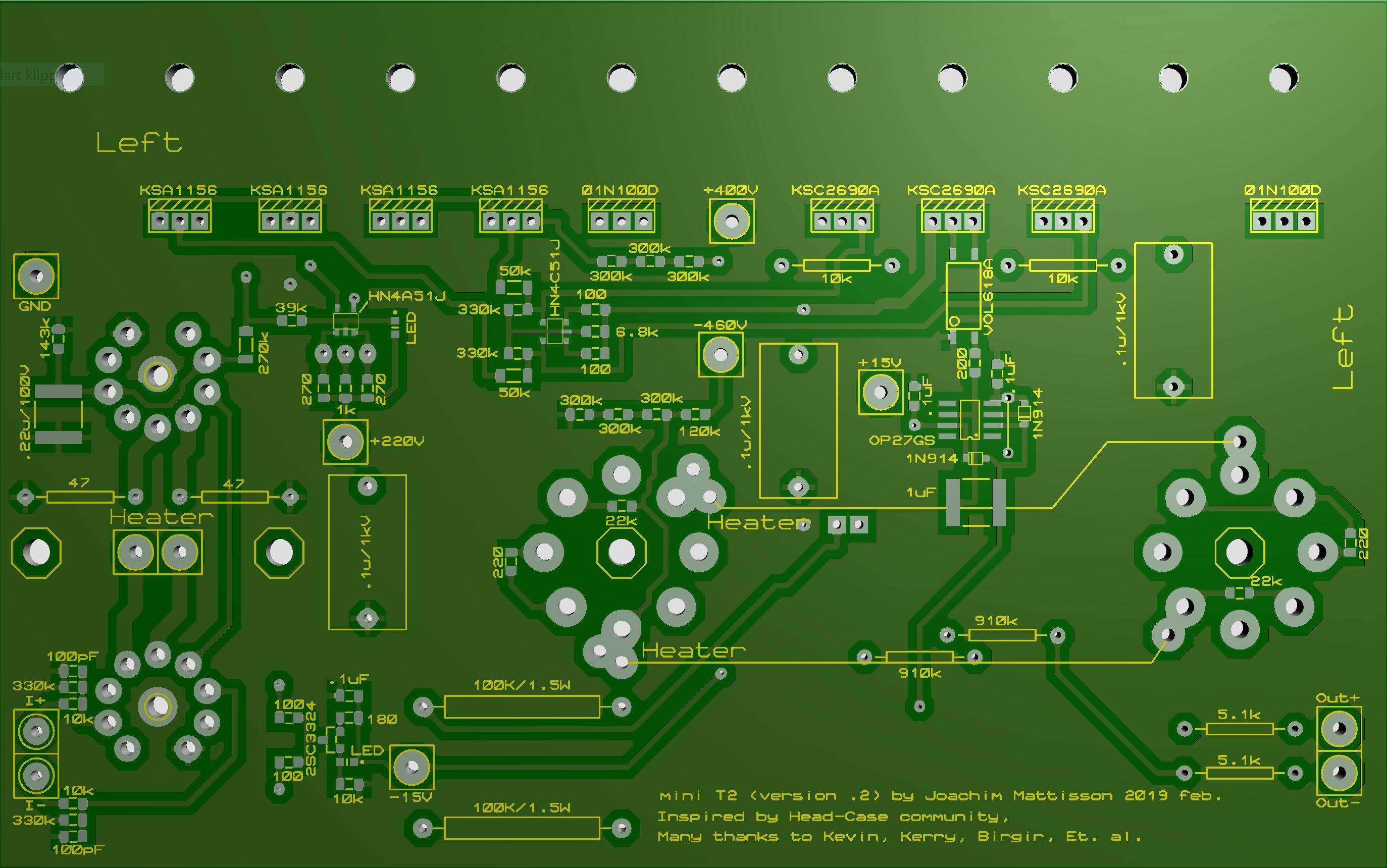
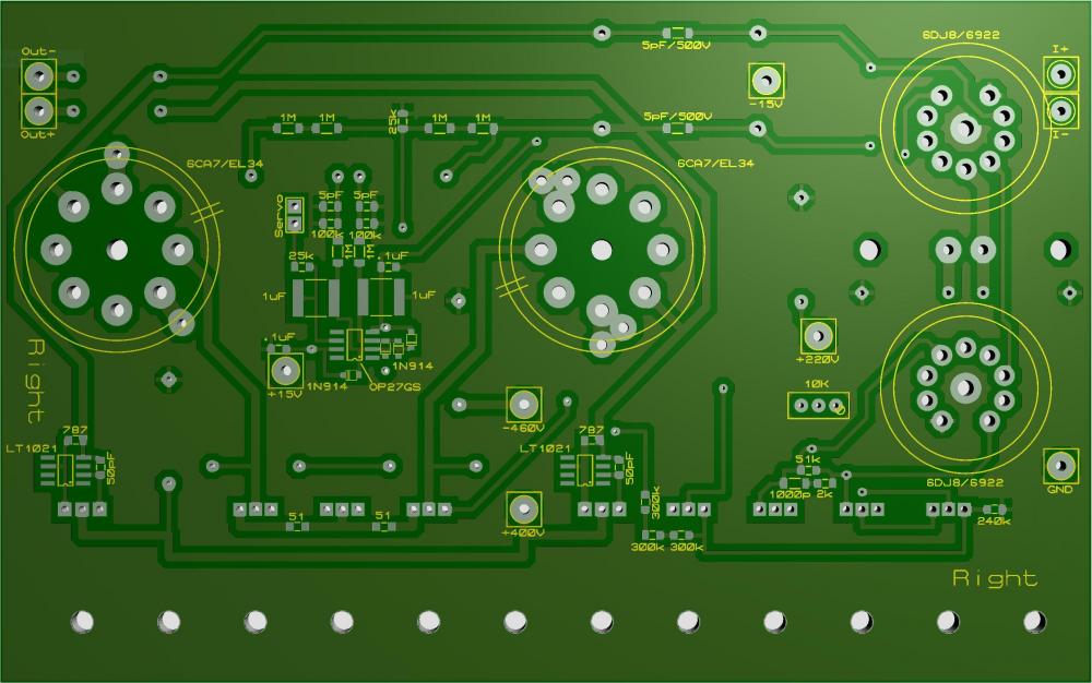
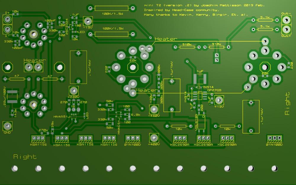
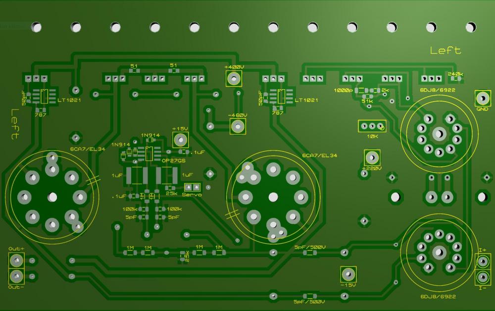
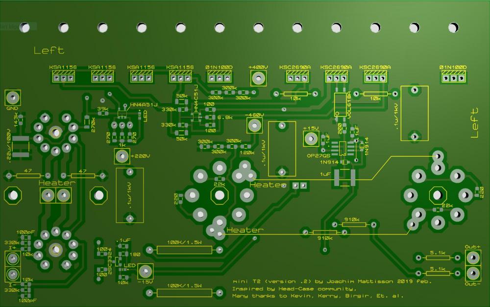
1 pointA few points regarding the boards Michael have had made on my gerbers. They are basically the same as my kitchen made boards I made five months ago. The small tube footprint has no hole for the center pin. So far I’ve cut away the center pin on the small tube socket after checking the pin holders to be not to tight nor to loose. One time I got tube sockets where the tubes fell out when turning upside down. So either you have to cut pin or drill a hole. Be aware that upper tube has a trace between the grids that might be to close to center pin. Right board 270K resistor has a 0805 pad (intention was 1206). It’s possible to solder a 1206 resistor on the 0805 pad. If +220V you get about 130 V cross the resistor so Vishay CRCW0805 is OK here. But with +250 V you get close to CRCW0805’s limit of 150 V. Some of component values on silk screen are poorly place and almost unreadable. The blame is entirely on me, I’m very sorry. There are four octagons on bottom side. One at each big tube socket center hole and one each side of small tubes filaments connections. Here I have standoffs. A few comments on updated layouts. Small tube footprint with center hole. 270K resistor pad corrected - now 1206. Silk screen remade. Pleas notify me if there is any left that needs additional attention. Now “value” of connections on both sides (except heaters). No terminal blocks on my boards. Top right. Updated 2019-02-27. Bottom right. Updated 2019-02-27. Top left . Updated 2019-02-27. Bottom left. Updated 2019-02-27. I call above version .2. My kitchen made and Michaels are version .1. Regarding this amplifier - there is nothing I've invented. I just have picked up different things and tried to put them together. As: Opto servo (the only offset servo you need) by Kevin. 01N100D/TL1021 current source by Kerry. Schematic of Stax T2 provided by Kevin, Et. al. Schematic of Stax T8000 provided by Kevin and Birgir. Etc. etc. Thanks for all knowledge, information and inspiration from you DIYers and Head-Case members. Please look for errors or other issues.
 1 point
 -
1 pointMy sister just moved back to the area, so I went and saw her. And gave her the Malbecs. There was even one Norton Reserva in there.1 point
-
1 point
-
1 pointOK – Connected an unmodified T2 PSU. Raised voltages to +250 and +/-500V. Top 6922 anode voltage sits at 227V and grid at 78V. So far it works. Will run this for a while and check for darkening spots on the boards.1 point
-
1 point
-
1 pointOoh that's big news! I liked being co-gentlemen of leisure though. Might pout.1 point