


ujamerstand
High Rollers
-
Joined
-
Last visited
Everything posted by ujamerstand
-
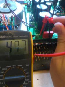
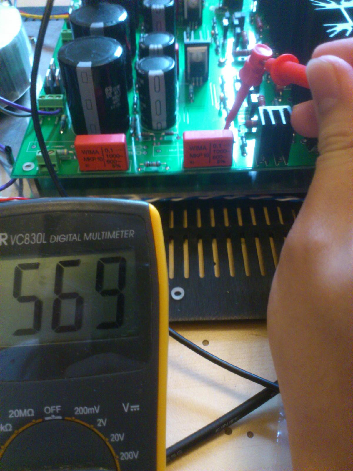
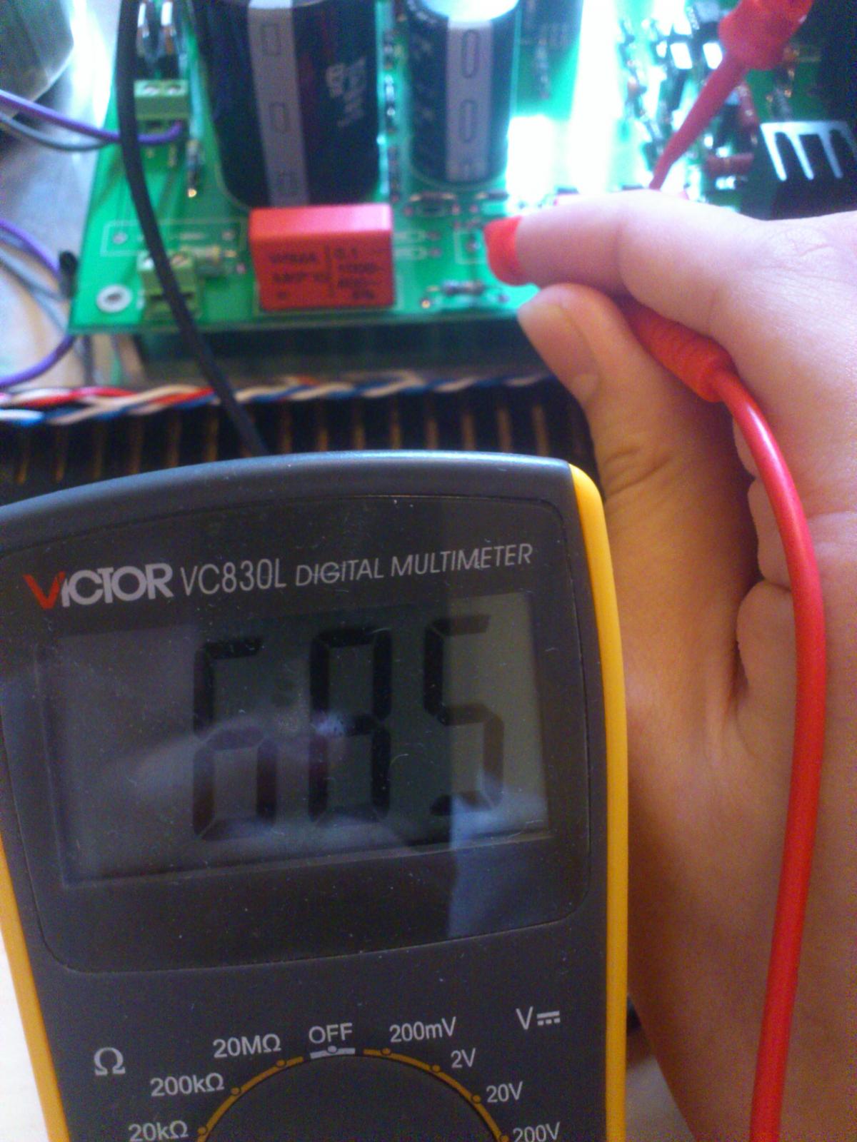
Why did you post that then?Gcongrats!![media=] I particularly like the part where he skips over the problem area in the frequency response graph.Any more progress in this area? I'm in the market for a nice and cheap instrumental amp.I was told that black teflon has impurities in it that won't like high voltages. I think the ones in that picture are CMC bakelite tube sockets?Congrats! So close now.. I'm also looking for an old pair of sr-sigma for the sigma404 mod. I've already got 404 drivers in storage. I hope I could find a pair somewhere soon...Forgot to specify how many pieces I'd like to have. I'd like to have 4 pro jacks please.We shall play some DoomV2. It's a great map to level up and get the hang of things.Server codec swapped to speex.Nice! Let me send this one to my sister. She loves making her own bread!Looks delicious!Happiest Birthday to you!Some images of the bias supply readout: jumper: zener string: before 4.7M resistor: Overall shot of the bias supply: Can I assume that the voltage drop over the RCRC filter is normal?


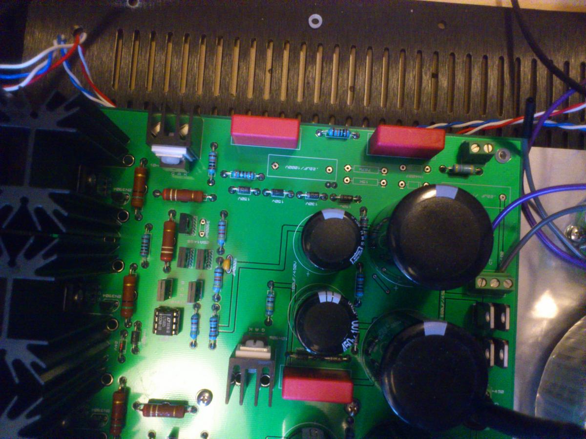
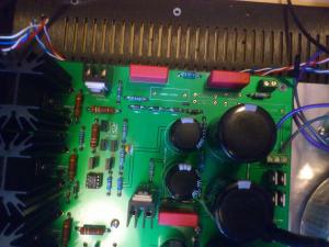 Actually, I'll have to take your words with a grain of salt. I'm sorry, but I don't know you, I don't know your technical background, and you've come in directly with a strong opinion about a product that's yet to be released. Please read the welcome PM again.I left out the voltage doubler. Connected the jumper. The voltage readings at the jumper was about 630VDC. Here's an image of the wiring when I was testing the negative rail. It should show the parts I left unpopulated. I'll take a better image tonight when I get home.
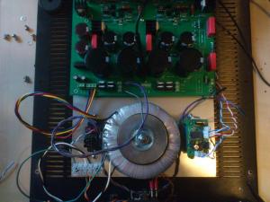 Thanks! Measuring before 4.7M to bias output gives me 480V, measuring the zener string gives me 580V. I'm guessing the RCRC filter dropped 100V. I'm also reading... 99VDC at the bias supply output; with reference to ground. I was using 1A fuse before. It immediately popped at start up. I think startup transient caused it to blow.My jacks followed the original plans directly; and some of my jacks are tighter than others. I think it depends on how the pins are inserted and soldered to the adapter pcb. One of them had a smooth fit before I soldered the pcb adapter on. After I soldered the pins to the pcb, more force is required to insert and remove the jack...Threw in a 3A fuse. No problem. regulates at 506V. Very Solid. Edit: Tested the negative postive rail separately. No problem. Solid regulation at +506V. Bias is very stable at 480V. Today is a happy day.I was just ganna post that! It's amazing!They've been making good progress on the display front for the raspberry pi:Go Grahame!


Important Information
By using this site, you agree to our Terms of Use.