sbelyo
-
Posts
1,052 -
Joined
-
Last visited
-
Days Won
1
Content Type
Profiles
Forums
Events
Everything posted by sbelyo
-
Those do work... I was focused on the 400V rating and didn't realize the different CAT rating thanks. What transformer did you use?
-
I measured the pin spacing on the boards as well as the BH Ultramini PSU. They're all 5.08mm The MKDSN series are all 7.62mm It doesn't look like they'll fit and I don't see anything in that size higher than 300V
-
I just realized that the terminal blocks should be high voltage as well. Jose, what terminal block are you using?
-
cool thanks
-
Thanks... Is metal film 1/4 watt 1% 100 ppm ok? Is one series better than another
-
Are these the right transistors? https://www.mouser.com/ProductDetail/ON-Semiconductor-Fairchild/KSC2752OSTU?qs=sGAEpiMZZMshyDBzk1%2fWi8oN7VHZ91OkpQ9k8BYJNao%3d https://www.mouser.com/ProductDetail/ON-Semiconductor-Fairchild/KSA1156OSTU?qs=%2fha2pyFadugv%2fWJliOE2i01ObXewH%2b9W60g4Ozyqyh8LU2w5on%2bF8w%3d%3d And for resistors I'm guessing RN60D's are ok?
-
That GTI color is dope though
-
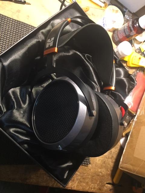
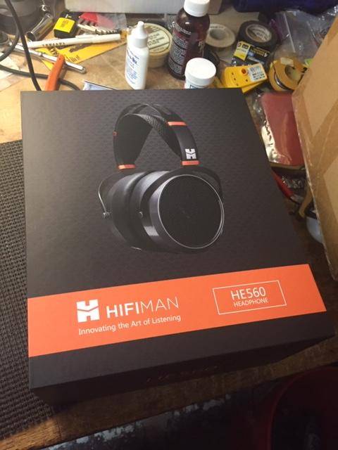
Got a pair of Hifiman he560 Excellent headphones. I had one slight problem with them as the highs are a little forward or bright (hopefully they settle down). You'll definitely need an amp though.

-
craptastic! Thankfully it's 39F with no precip here
-
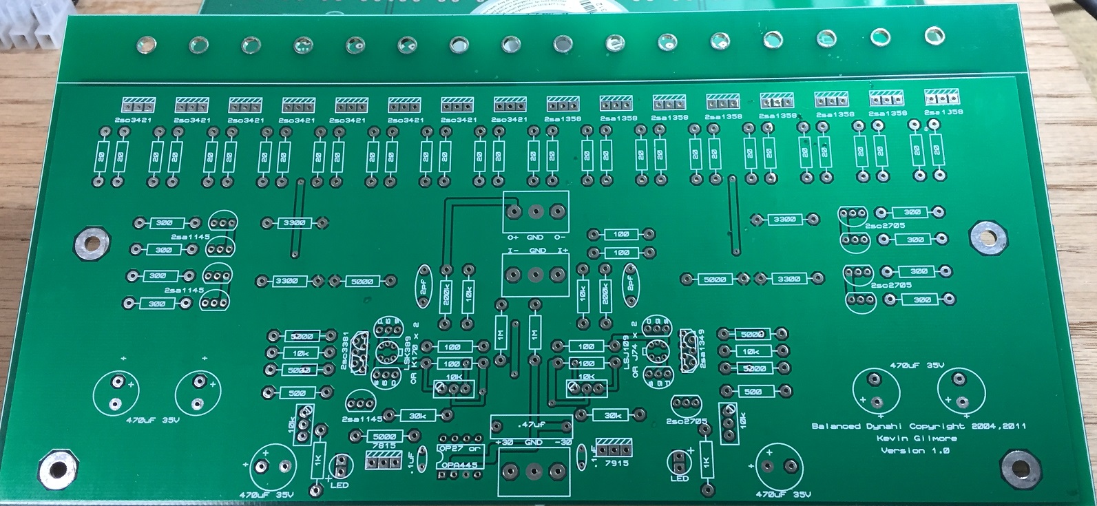
I'm wiring up (or getting ready to) a 2 box Dynahi build and a new Buffalo III pro build. If I read the Rane article, the Tortuga article, and this post correctly I should connect IEC inlet ground to the chassis, Pin 1 of each XLR to the chassis, and PSU ground to the chassis for each box, then float the pot grounds in the Dynahi amp box. Is that correct?
-
Thanks Pars... I sent the diyaudio person a PM. There was a US seller on ebay that had them listed for a while now and of course hasn't relisted them in a month. I'll see what happens
-
is there a reliable source for 2SJ109BL ? I need 2
-
no sweat man... Merry Christmas!
-
yeah, I eventually found that... I'll see what I can cobble together
-
definitely check the offset on that thing. Not sure how good this would sound probably need to do something like this http://www.dms-audio.com/power-amp-heaadphone-adapter I'll work for a bag a chips and a cold beer
-
If I take say 1 120 Ohm 5 watt wire wound resistor for each channel that's sufficient for a dummy load correct?
-
Got it... Thanks for the schematic Chris. It's the 200K resistors. The cap has to increase to 5 pf
-
I need to make sure what resistors are the feedback for gain. Are they the 10K or 200K on either side of the input?
-
looks good
-

accidentally shorted secondaries for 2 seconds, how do I tell if it's ok?
sbelyo replied to sbelyo's topic in Do It Yourself
good, no magic smoke -
accidentally shorted secondaries for 2 seconds, how do I tell if it's ok?
sbelyo replied to sbelyo's topic in Do It Yourself
Yeah, voltage seems ok. I'll go ahead and put it under load to see if it drops below the voltage that it should be -
accidentally shorted secondaries for 2 seconds, how do I tell if it's ok?
sbelyo replied to sbelyo's topic in Do It Yourself
it did, I thought I had a very small fuse in there. Put a bigger one in and it held -
OK, so I did something stupid and accidentally shorted the secondaries of an Avel Lindberg Y23 transformer for two seconds. The voltage seems fine after I corrected the error. Do you think it survived, and or what's the harm in using it?
-
loved that show... it's on sometimes daily where I am
-
lol, yep. Luckily I work from home. The cars were already encased in at least a half inch of ice while I was untangling the cord