JoaMat
-
Posts
1,558 -
Joined
-
Last visited
-
Days Won
16
Content Type
Profiles
Forums
Events
Everything posted by JoaMat
-
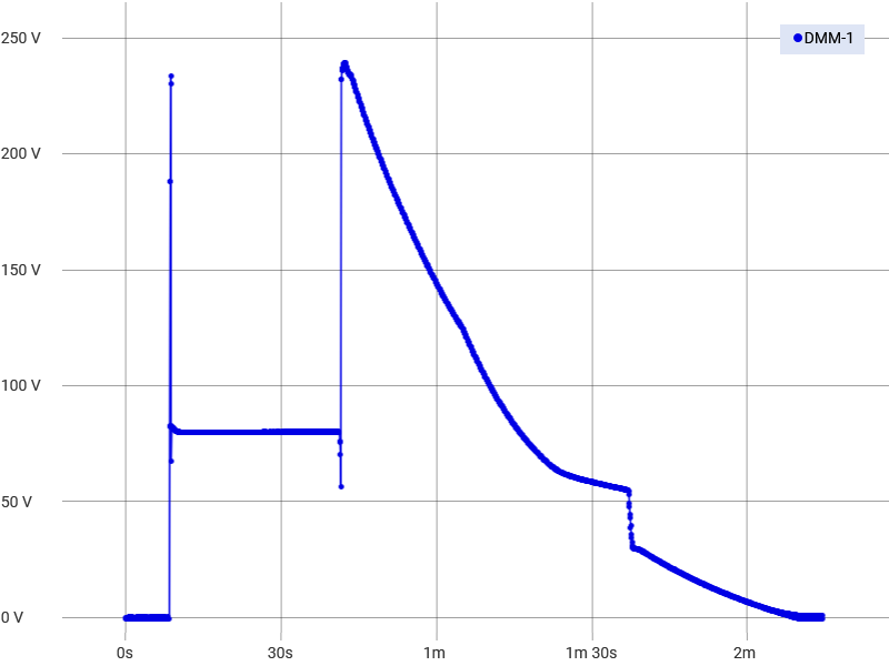
A few years ago I replaced 2sj79 and 2sk216 with ksa1220 respective ksc2690 on both Blue Hawaii and T2 and that without changing any voltages. Below chart show voltage cross source and drain on T2´s Q26,Q27 during power on, 30 second wait and power off. So far I haven’t had any ksa1220 or ksc2690 blowing up. Today I reduced voltage further on my T2 PSU, 300V section now 200V. Seems to work as good as with 300V. High voltages are now +/-400V, +220V, -260V and -460V. The reduce voltage also lowered the maximum voltage on graph above to 200V

-
A belated Happy Birthday!
-
Belated Happy Birthday!!
-
Thank you everyone. Wife and I had a nice medium long hike in beautiful winter weather. Wish you all well.
-
Merry Cristmas to you all
-
-

Megatron Electrostatic Headphone Amplifier
JoaMat replied to kevin gilmore's topic in Do It Yourself
i'm done
-
-
Megatron Electrostatic Headphone Amplifier
JoaMat replied to kevin gilmore's topic in Do It Yourself
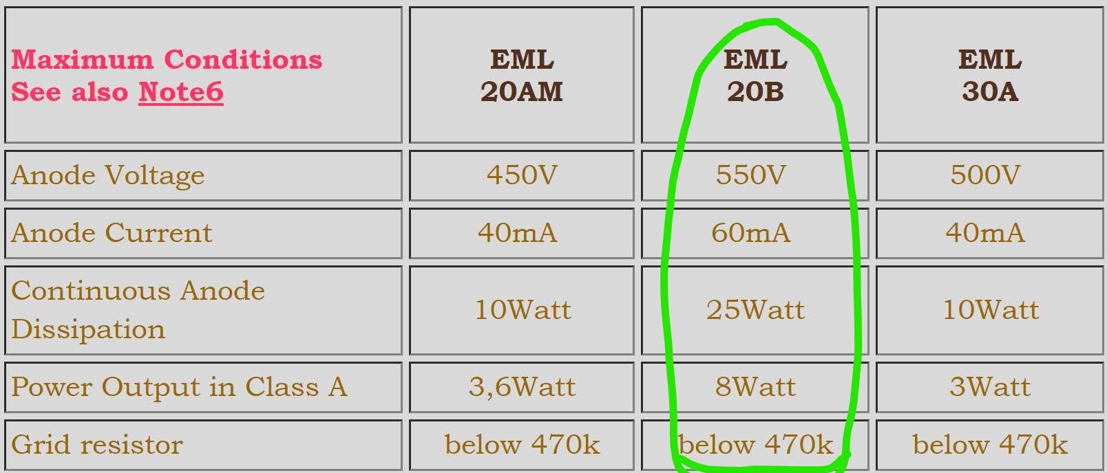
This Emission Labs amplifier wasn’t planned, it just happened along the way. Although it seems to work, I have no idea how to best use the direct heated triodes in an electrostatic headphone amplifier. Here are maximum conditions stated in datasheet from Emission Labs with note 6. Note6) Maximum conditions do not apply simultaniously. This is not a working point. I think I’m within most of the maximum limits, but what how about Power Output in Class A: 8W and Grid resistor: max 470K? Is there anything to consider in my case? Now I’m running at 400V/27mA roughly 11W and grid resistors are 680K as in the original Megatron. Any advice and comments are appreciated.
-
Megatron Electrostatic Headphone Amplifier
JoaMat replied to kevin gilmore's topic in Do It Yourself
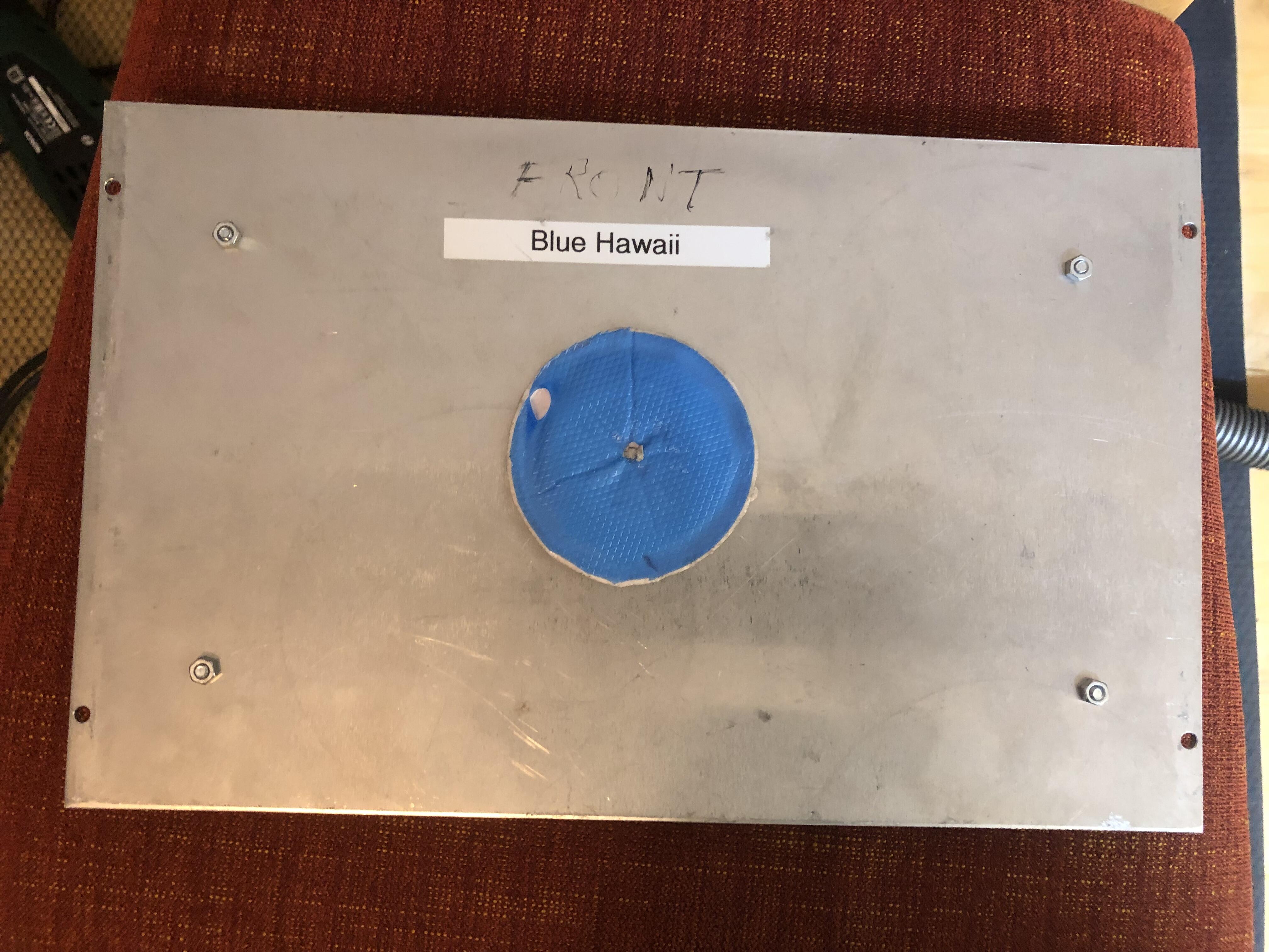
Here is my solution for filament transformer… …mounted on bottom case plate, belonged to a now retired Blue Hawaii. I also found a piece of Bergquist Gap Pad for the transformer to rest on. It seems that cathode resistor voltage is much lower for Emission Labs tube than for EL34, so I decreased the negative high voltage from 460 V to 400 V. The lowered voltage called for change of Cathode resistor and trimmer, now 402R resistor and 100R trimmer. A few things had to be removed before component changes.
-
Megatron Electrostatic Headphone Amplifier
JoaMat replied to kevin gilmore's topic in Do It Yourself
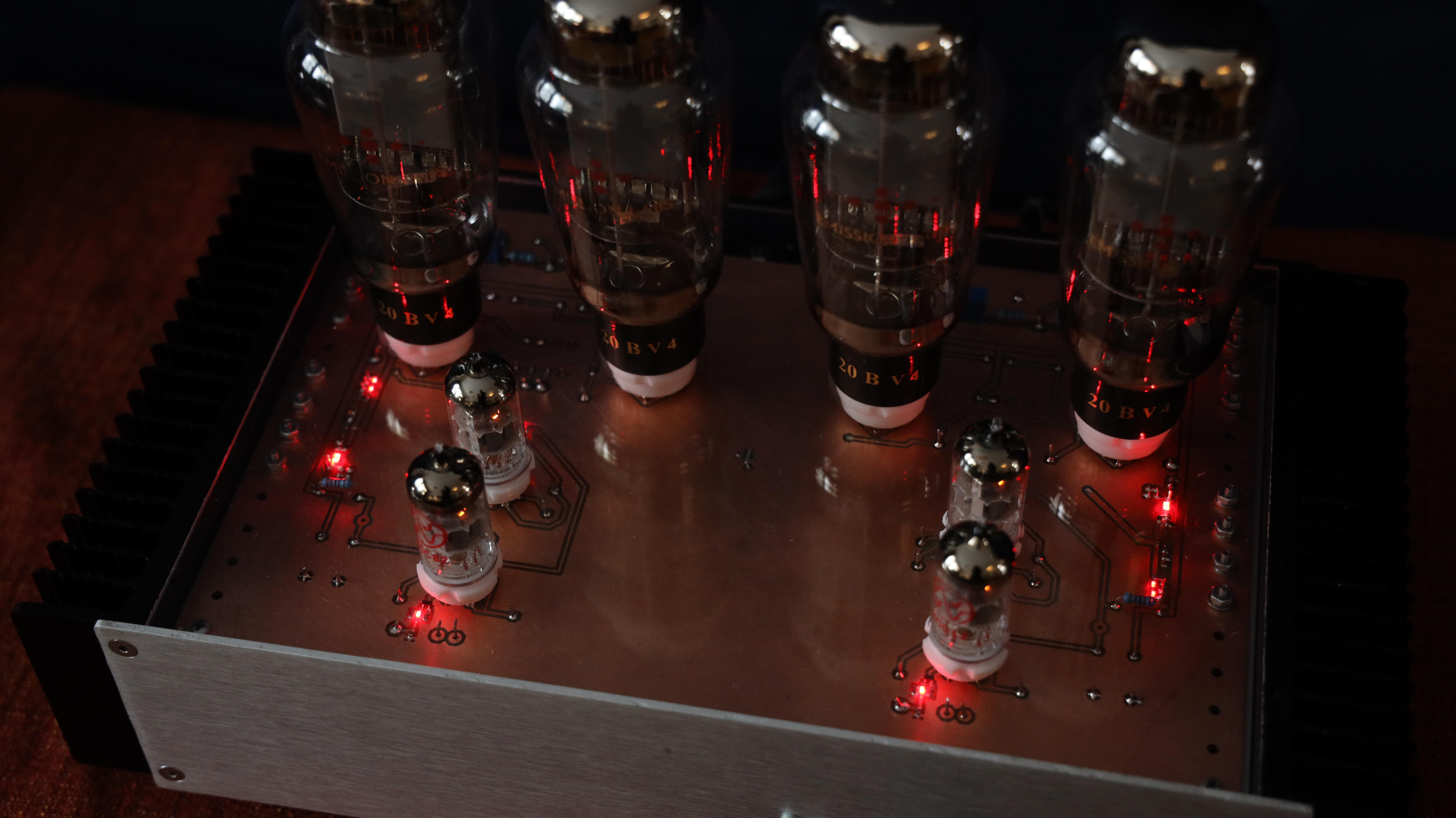
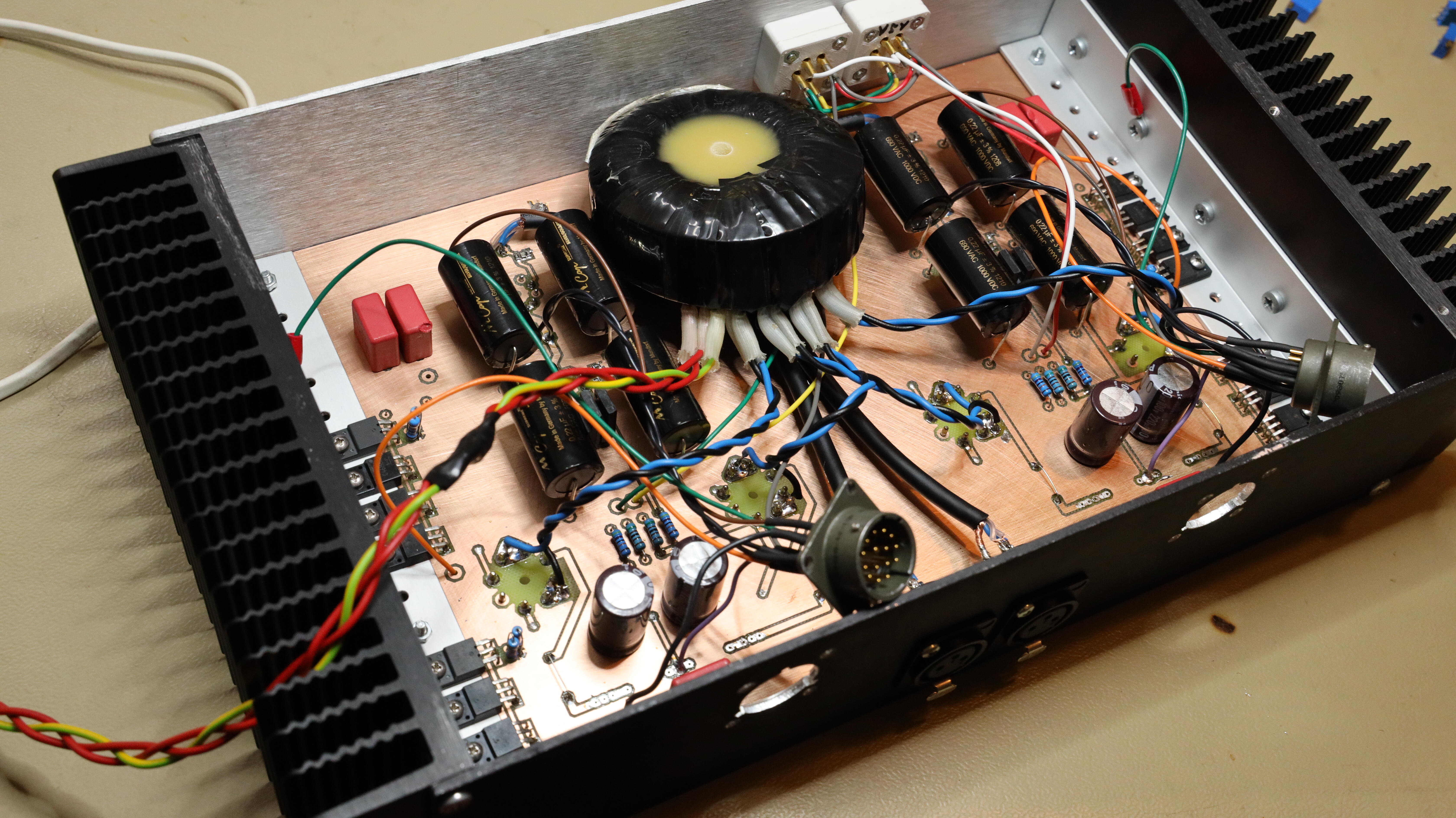
Now my Emission Labs tubes finally have gotten a dedicated DHT amplifier. Picture is taken in almost complete darkness, so most of the light comes from LEDs and tubes. Current is 27 mA which gives a voltage of 15V cross cathode resistor. Filament transformer is on the bench behind the amplifier - I have to find a more permanent solution I guess…
-
That looks great! At picture above, are you removing copper with a 2mm end mill?
-
Megatron Electrostatic Headphone Amplifier
JoaMat replied to kevin gilmore's topic in Do It Yourself
I do think it will be with direct heated transformer in amp chassis and my original external PSU. The amphenol connectors have no free positions plus it’s 5VAC tor the Emission labs filament. …but if I put one transformer in amp house, I might very well put everything in the same house? Then it will be my first single chassis build. -
Megatron Electrostatic Headphone Amplifier
JoaMat replied to kevin gilmore's topic in Do It Yourself
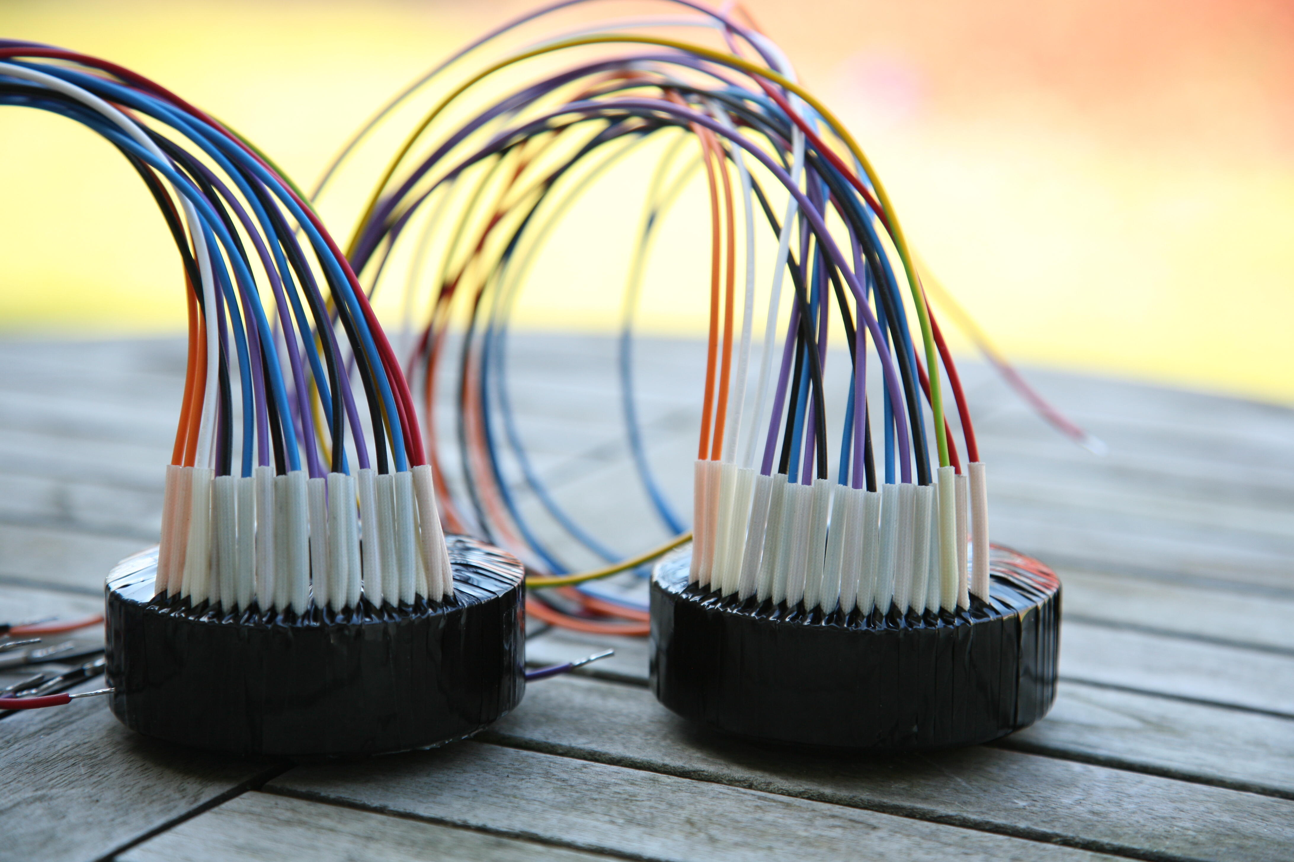
The milling machine has been busy today. Width is same (to the last decimal) as Kevin’s original DIY T2 board but only half the length. Transformers for 4 direct heated triodes (each). Need a hair cut.
-
stax mafia circuit boards see updated links on page 5
JoaMat replied to kevin gilmore's topic in Do It Yourself
No need for old laptop. It seems as 8.5 works along with new version if they are installed in different maps. -
stax mafia circuit boards see updated links on page 5
JoaMat replied to kevin gilmore's topic in Do It Yourself
Thanks. So, I better keep my old out of date lap top with 8.5 installed to be able to view gerbers. -
stax mafia circuit boards see updated links on page 5
JoaMat replied to kevin gilmore's topic in Do It Yourself
I’m trying to open Kevin gerber files in a newer version of Proteus and I get this message “Cannot parse all drill tool information from 'NC Drill Setup' section of the tool information (read-me) file.” and “Failed to successfully parse tool information (read-me) file. Gerber view aborted.”. In Proteus 8.5 gerber viewer works just fine. What might the problem be? Any idea how to solve it are appreciated. -
Megatron Electrostatic Headphone Amplifier
JoaMat replied to kevin gilmore's topic in Do It Yourself
After yesterday’s post I thought the project was completed. But no, not completely… how about the EML direct heated triodes? Tubes with their filament injector adapters and “portable” filament transformer. I had to decrease cathode resistors to approach a good offset. For the moment output current is set to approximately 19 mA, only 2 of 3 2SC4686 in each CCS are in work.
-
Pertusi - Michele: Live Recital
-
Megatron Electrostatic Headphone Amplifier
JoaMat replied to kevin gilmore's topic in Do It Yourself
Here is another picture of my megatron something. Made the fifth board in this small project yesterday, seen at left side. Main reason for this project is that I had Mundorf capacitors just laying in a “good to have bin” and, I also have too many unused 2SC4686 and 2SA1968. You can build a similar amplifier with 4 x KSA1156, 4 x 01N100D and 4 x DN2540. Plus, tubes and a few passive components. The easiest electrostatic tube amplifier I’ve built so far.
-
Megatron Electrostatic Headphone Amplifier
JoaMat replied to kevin gilmore's topic in Do It Yourself
A report from JoaMat Kitchen. My idea of a servo as shown in a 3D visualizer a few posts up doesn’t make anything better, unless you like aerobatic inverted high g flights. If you want a nice ride just pull the jumper which disables the servo. Glad I didn’t gave that layout a version number. -
Megatron Electrostatic Headphone Amplifier
JoaMat replied to kevin gilmore's topic in Do It Yourself
Thanks for the suggestion. 🙂 But the amplifier is too good for having my "name". It’s a Gilmore design combined with JimL cascode CCS or T2 CCS. I have tried both, my privilege as a DIY:er. -
Megatron Electrostatic Headphone Amplifier
JoaMat replied to kevin gilmore's topic in Do It Yourself
I’m still working with “Megatron something”. Here is another version. Similar to earlier, but no trimmers. Room for 3W cathode resistors and opto servos (the only servo you need). I built an original Megatron back in 2013, but it’s disassembled long time ago and that was kind of a challenge, top tubes with separated floating filaments. I must say this is a bit easier and sonically it’s all right. I can’t call this Megatron, can I? I’m thinking of Hybritron – a combination of Hybrid (tubes and solid states) and Megatron. Or maybe I just call it my little ampy. Don't want to be sued by Bourns.
-
Megatron Electrostatic Headphone Amplifier
JoaMat replied to kevin gilmore's topic in Do It Yourself
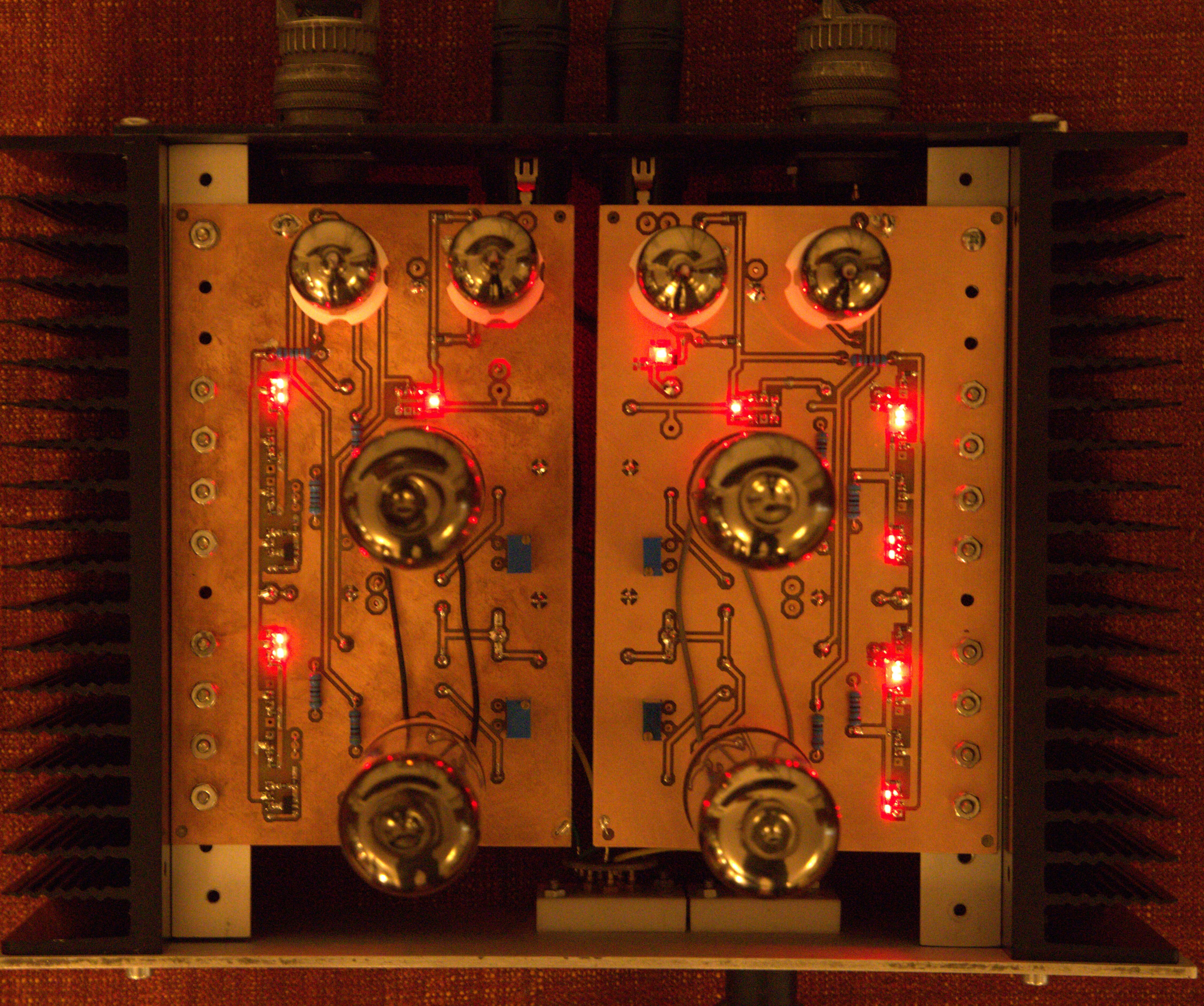
Just made a third board (right side) of “Megatron something”. Output CCS are T2 style - 3 x 2sc4686 and 2sa1968. All ten LEDs are on top side of board. I’ve to compensate for the missing tubes. Picture is shoot in weak light, ISO 12800 and 1/6sec.
-
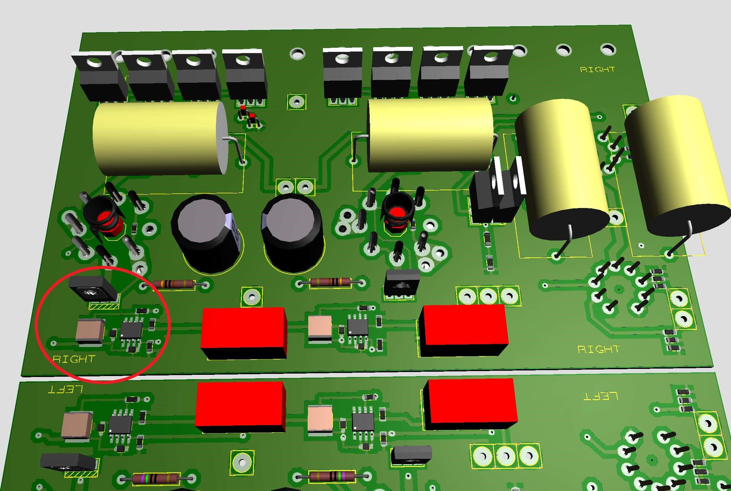
It really made my life a lot easier when I started to use integrated schematic. But if schematic is wrong, this might happen… Interesting project you have, AlexS.


.JPG.e9d82a14e65d54f960d5b4ce39632b17.JPG)

.jpg.f4872d586d2dd0f46daead3b4184fbc6.jpg)
.jpg.12f22c2c017ad2733d9667281546414f.jpg)
.jpg.446a352eaf9361a499783a106794cbb0.jpg)
.jpg.c72f472614f57135ec985664ab633fae.jpg)

.jpg.429d5863dbb97a4a05b503a0940c3956.jpg)