JoaMat
High Rollers
-
Joined
-
Last visited
Everything posted by JoaMat
-
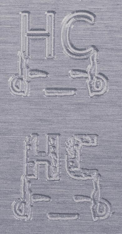
I somehow managed to copy H and C from HeadCase logo and mill it on the plate. picture in B/W
-
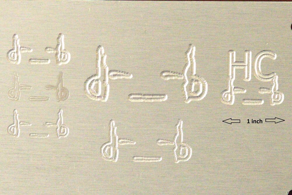
Have made a few test inscriptions on aluminum with CNC machine.
-
Learned how to engrave with my milling machine today. It's an original Kevin Gilmore et. Al. DIY T2 amplifier with original parts.

-
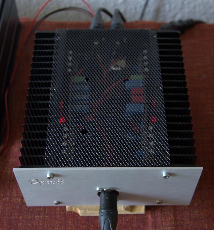
Milled a front panel, with inscription, today. With black painted aluminum net as top cover you can see the light from eight red LEDs.
-
vojne vojne, I’m old enough to have had two screaming teenagers in the house… phuuu
-
Free speech gives you the right to be silent.
-
vojne vojne
-
...and now a stereo version. Bias 75mA, 125 degrees F at heat sinks and AMB sigma PSU is working hard. Might need better chassis.
-
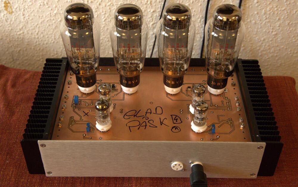
mini T2 with Emission Labs Directly Heated Triodes. It didn’t blow up. Left channel offset servo didn’t work so I replaced its ksc2690 with a 1K trimmer. GLAD PÅSK! written on the copper clad is Swedish for Happy Easter!
-
I came across IPC2221A years ago when I started to make my own uncoated home-made boards falling in category B2. Following the document would have had a huge impact on my layouts. But as a DIY:er I’m entitled to do whatever I like so I went with a clearance of 40th as standard with ground plane both sides. So far, I haven’t noticed any problem due to the clearance.
-
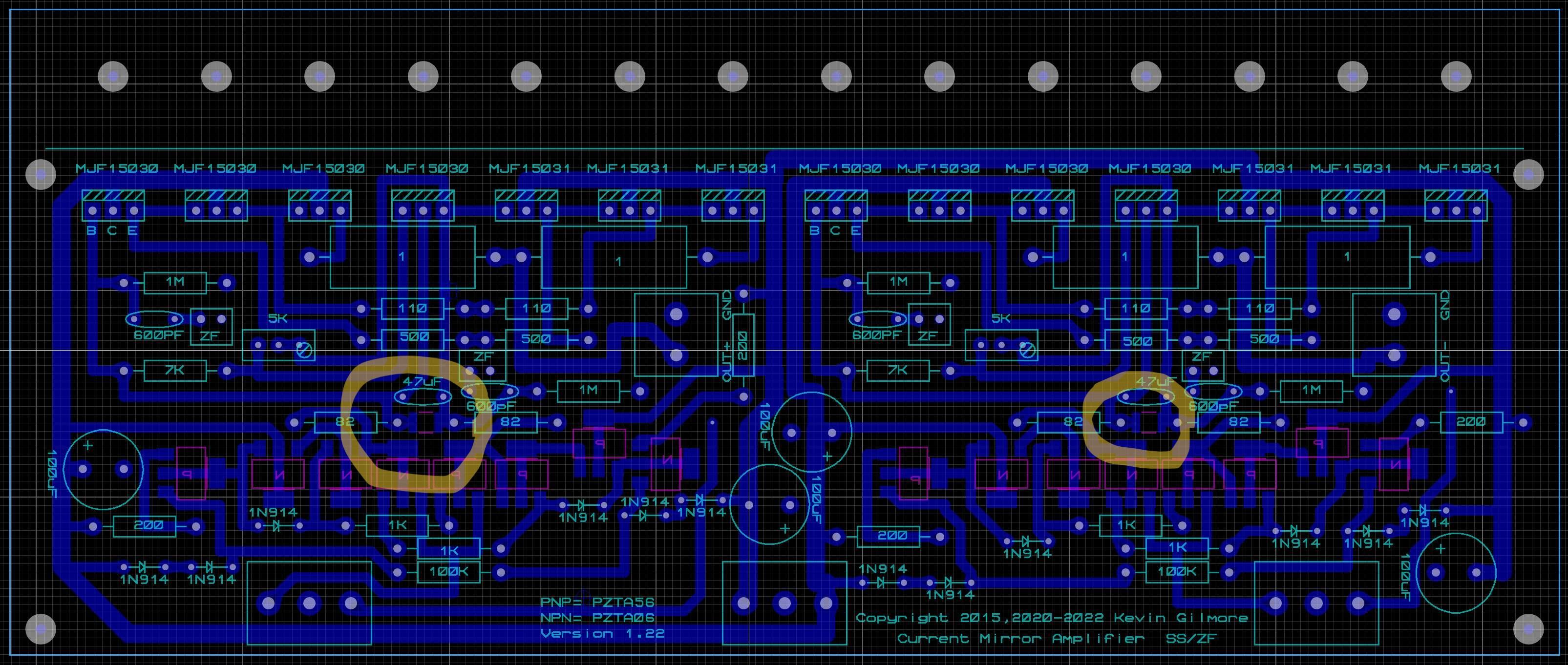
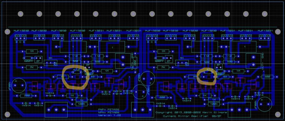
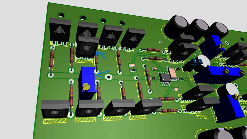
On the split CFP3 power board it seems to be some pads between the 82R resistors on the bottom layer. What might the purpose of them be?
-
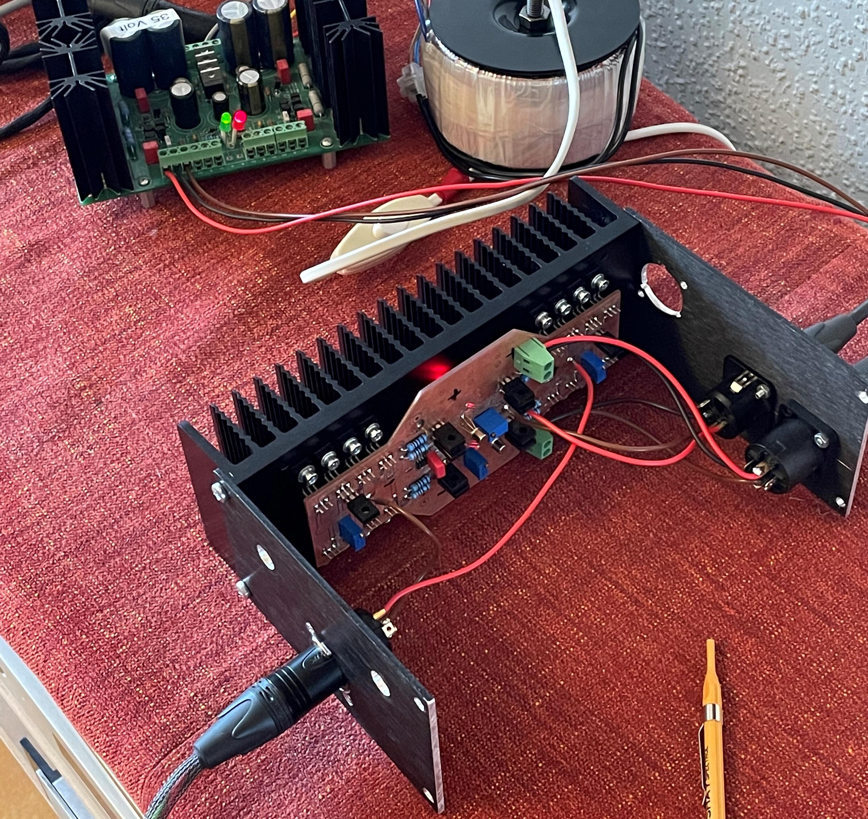
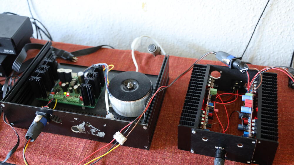
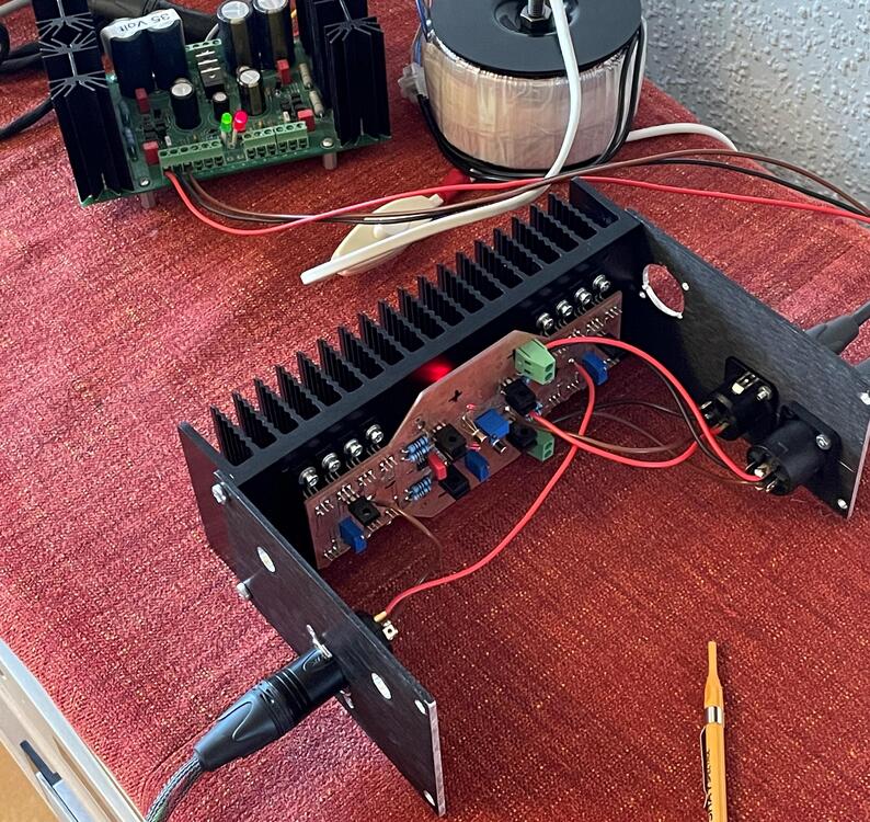
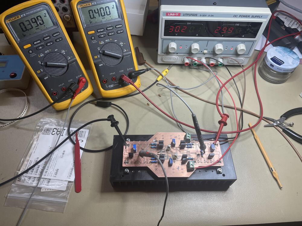
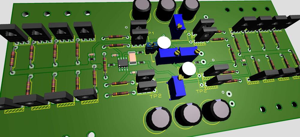
Here is picture of the amplifier in work. Mono version. AMB sigma 22 PSU. It has four trimmers. Lower middle controls the offset. Middle upper controls the balance. The two outer controls respectively channels bias. Input stage current source/sink approximately 1.7 mA. Output bias 35 mA. Setup procedure I used: • Let heats sink get warmed up to working temperature • Trim offset to zero • Trim balance to zero • Set desired bias of both channels to desired bias Redo previous procedures if needed. I find the setup easily done.
-
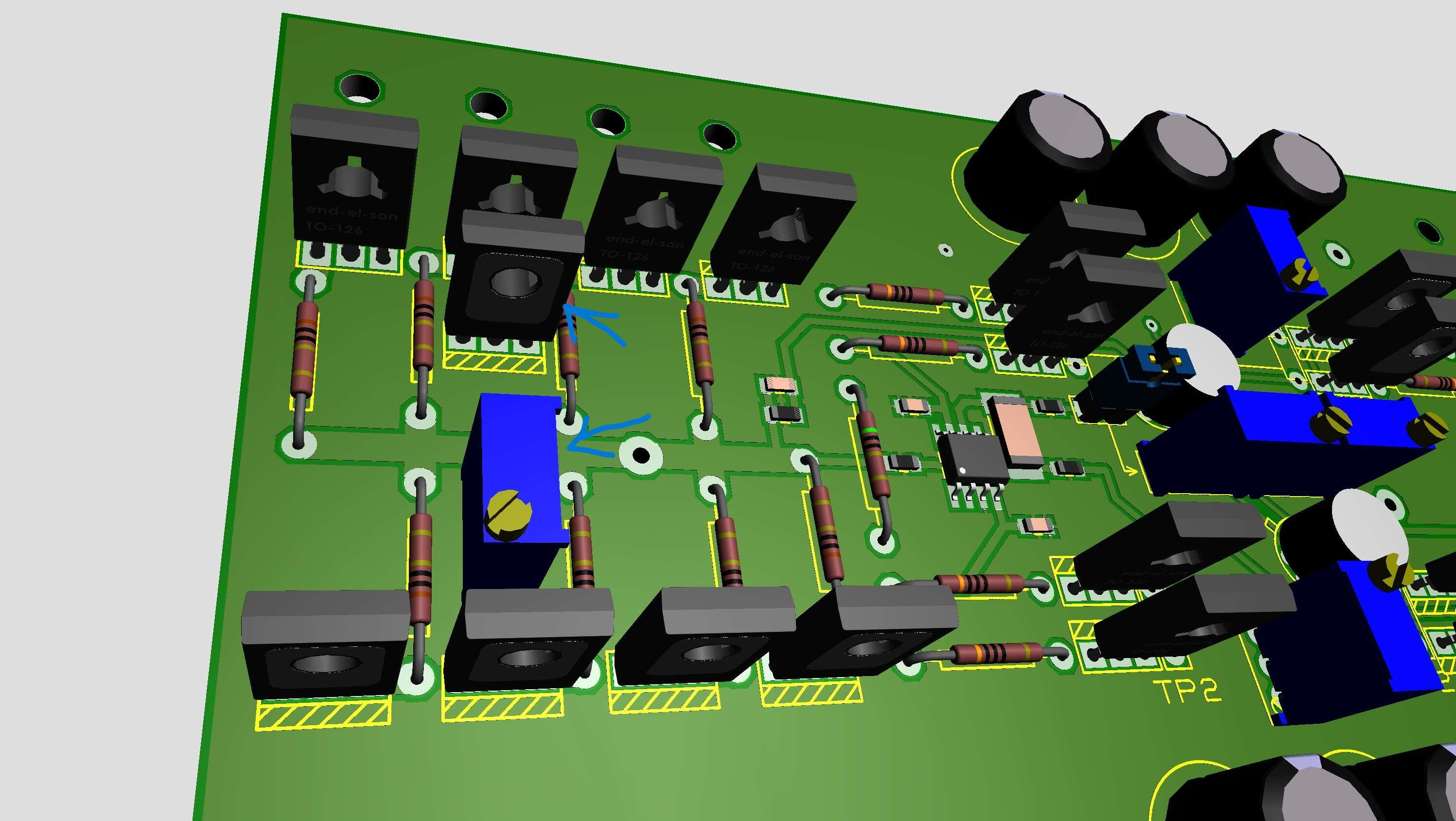
Interesting ideas, wish list, for future Dynahi, Bespav. Here is a new amp board. Initial tests have been successful. The bias control seems to work. Heat sink is Modushop 80mm x 200mm.
-
-
-
Just want to add that the bias control is not my invention. You find similar on Uberamp and AMB’s beta22. My view on Copyright is - my right, as DIY:er, to “copy and paste” as I wish.
-
Added a NPN, a trimmer and some resistor. With those it should be possible to set current through output transistors. Well, that’s the idea. If it works I probably let you know…
-
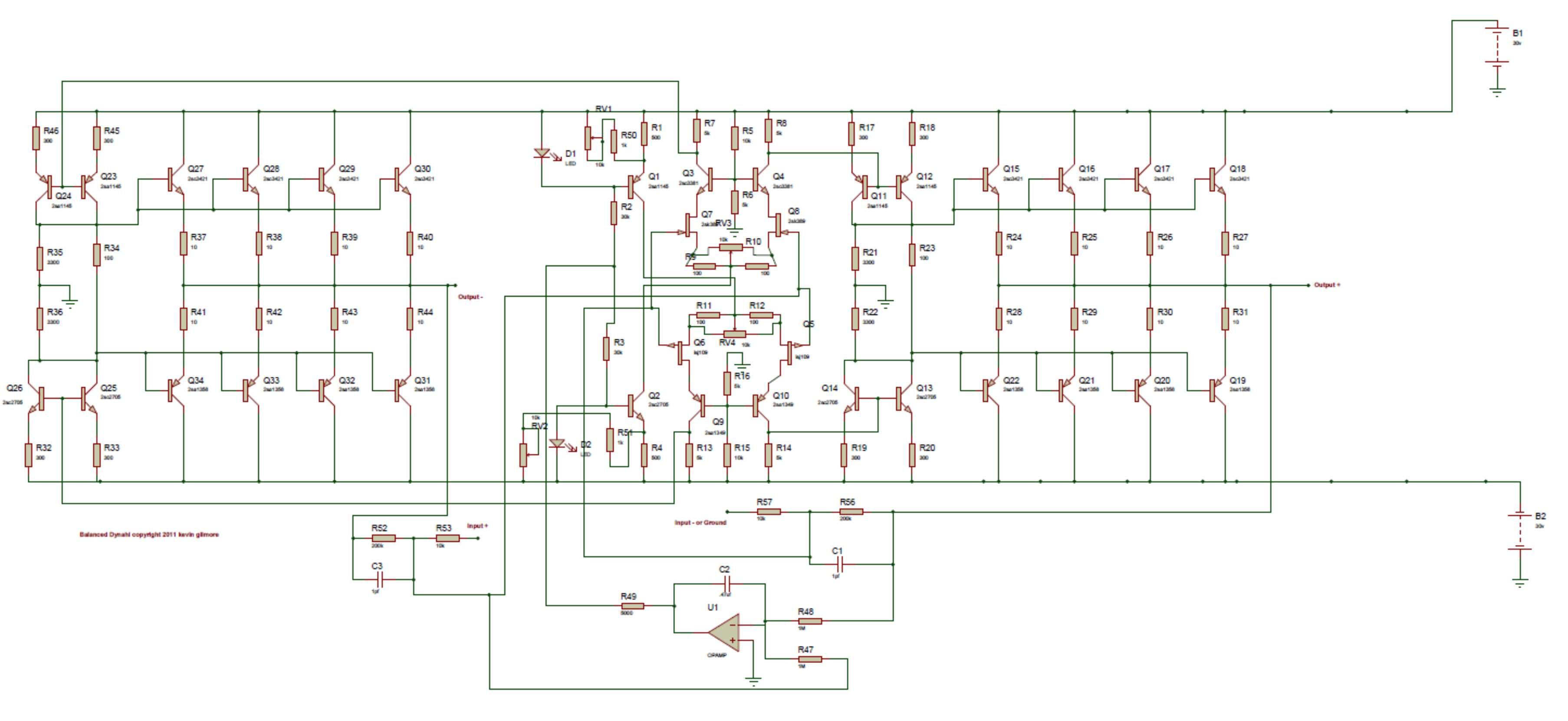
Senior HeadCase member MLA has lent me his Dynahi. A week listening to it have convinced me that one actually can listen to non-electrostatic headphones. So here is my first attempt... ... a balanced something with lsj689 and lsk489. And as always everything I make is based on a Kevin design. In this case on the famous Dynahi.
-
Happy Birthday!
-
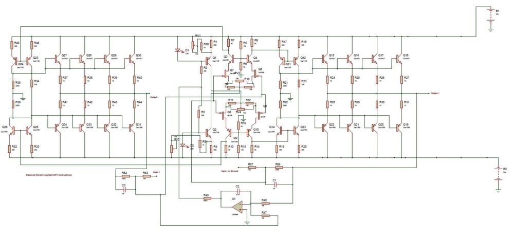
They are R23/34 in schematic: dynahibal1.pdf
-
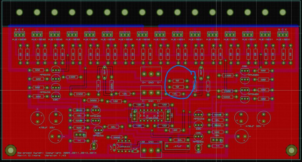
Circled 50R resistors seem to have been 100R in earlier versions of Dynahi. What might the reason for the change be?
-
Group of the 3 Devils (D3): Russia, China and Iran. Who are the additional candidates for D8 and D20?
-
My simple brain thinks that the democratic world and its financial systems have cultivated Putin, his oligarchs and strongmen as sourdoughs. Now Russia is capable to destroy life for millions of people if NATO doesn’t engage. If NATO engage Putin’s only defense/threat is nuclear weapons. God bless us all!
-
Happy Birthday!
-