


JoaMat
High Rollers
-
Joined
-
Last visited
Everything posted by JoaMat
-
The output transistors are 2sa1860 and 2sc4886 - right?
-
Looks like transistor at heat sink are TO-220. Aren't the output transistors something bigger – TO-3P - so the board need a stretch?
-
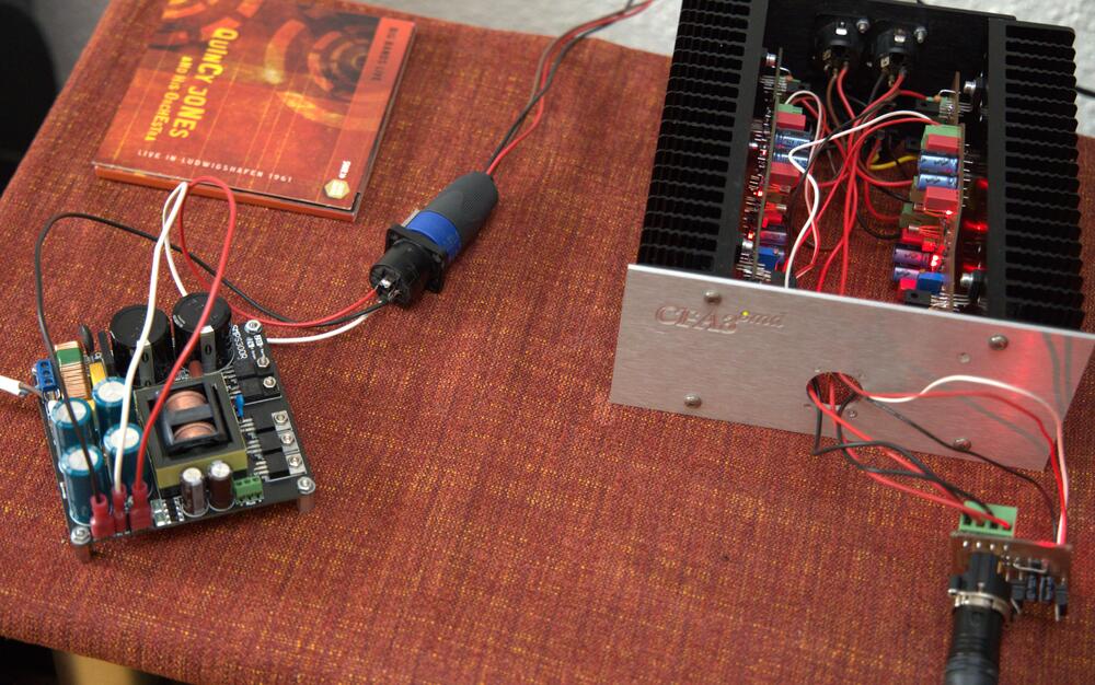
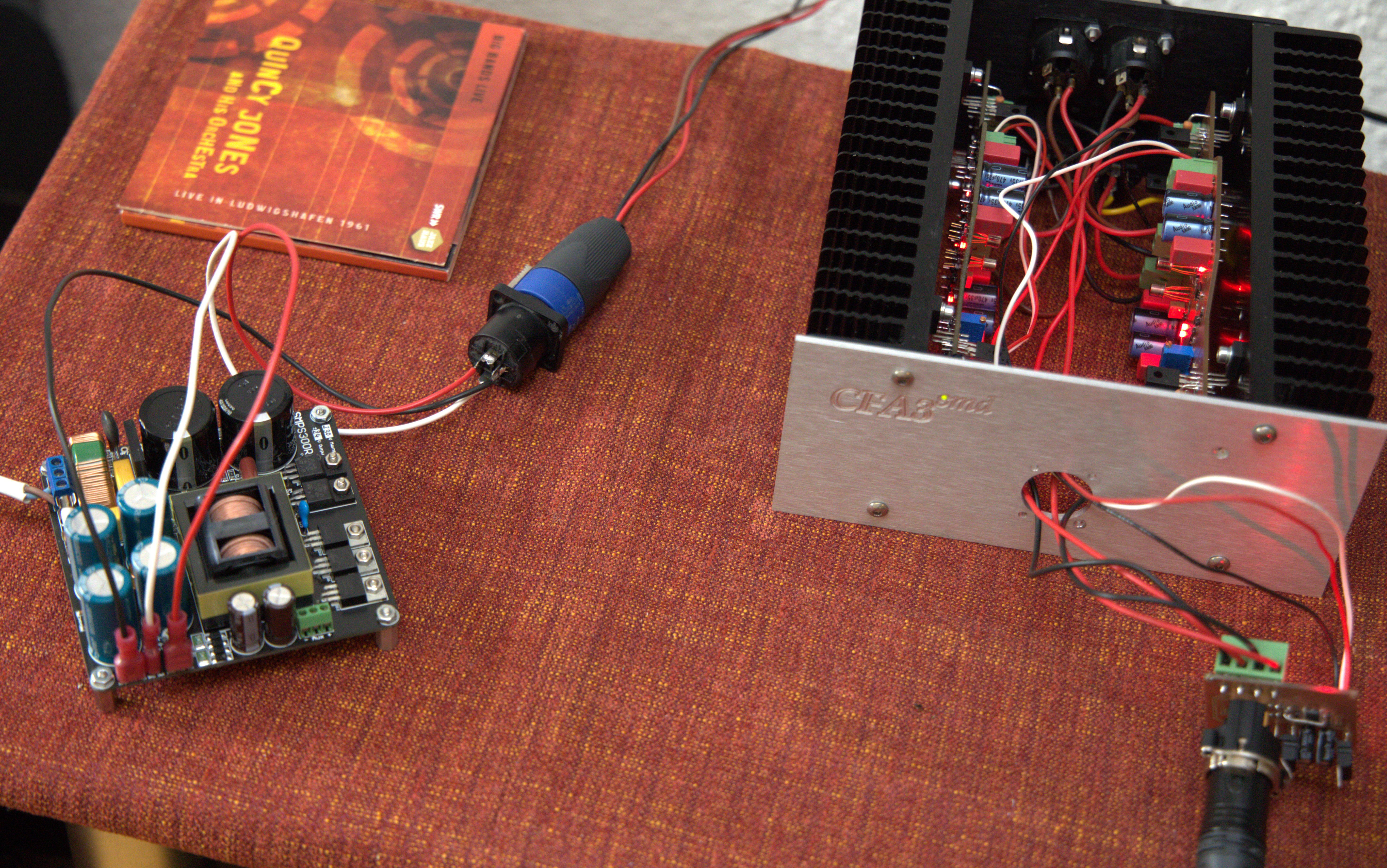
Now I’ve listened to CFA3smd something with switched mode power supply for almost 2 months and I’m happy with it. So, no plan for a golden reference supply. I’m too lazy and I think the switched power supply is good enough for me. Next “project” is how to power a Tube Hybrid. The Hybrid needs +100V, -5V and 6.3VAC for the tubes. The PSU has to be rebuilt. The amplifier board is finished, in theory…
-
Maybe DN2535 (max voltage 350V) will work. Main difference to DN2540 (max voltage 400V) seems to be the maximum voltage. In stock at Mouser for roughly the same price as DN2540.
-
-
thanks
-
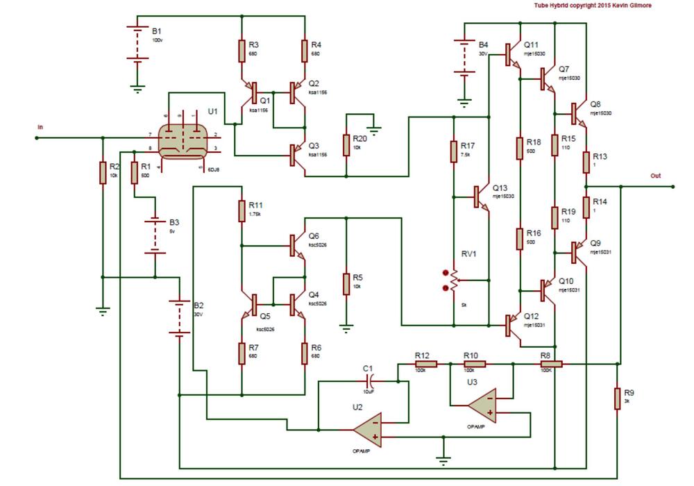
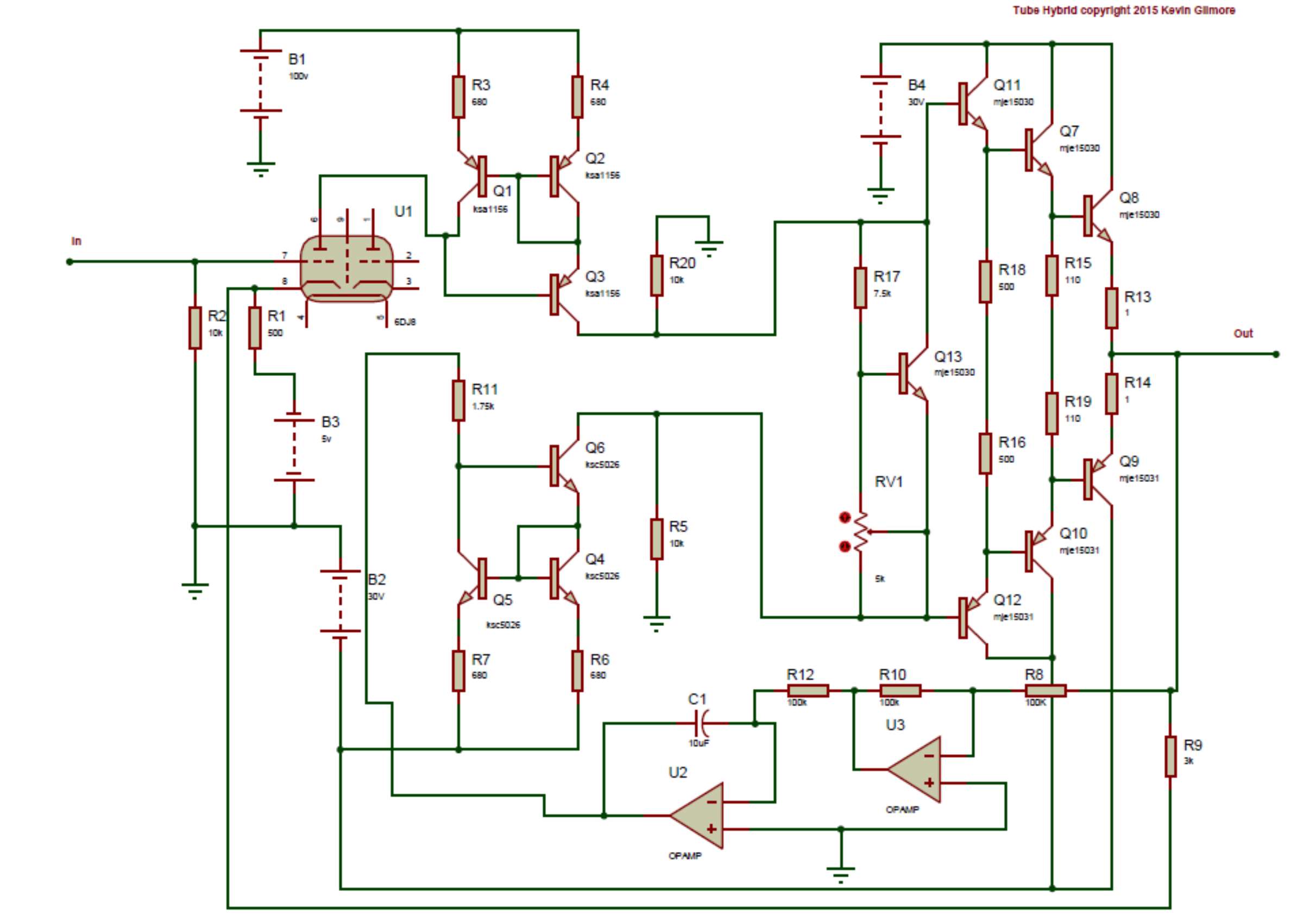
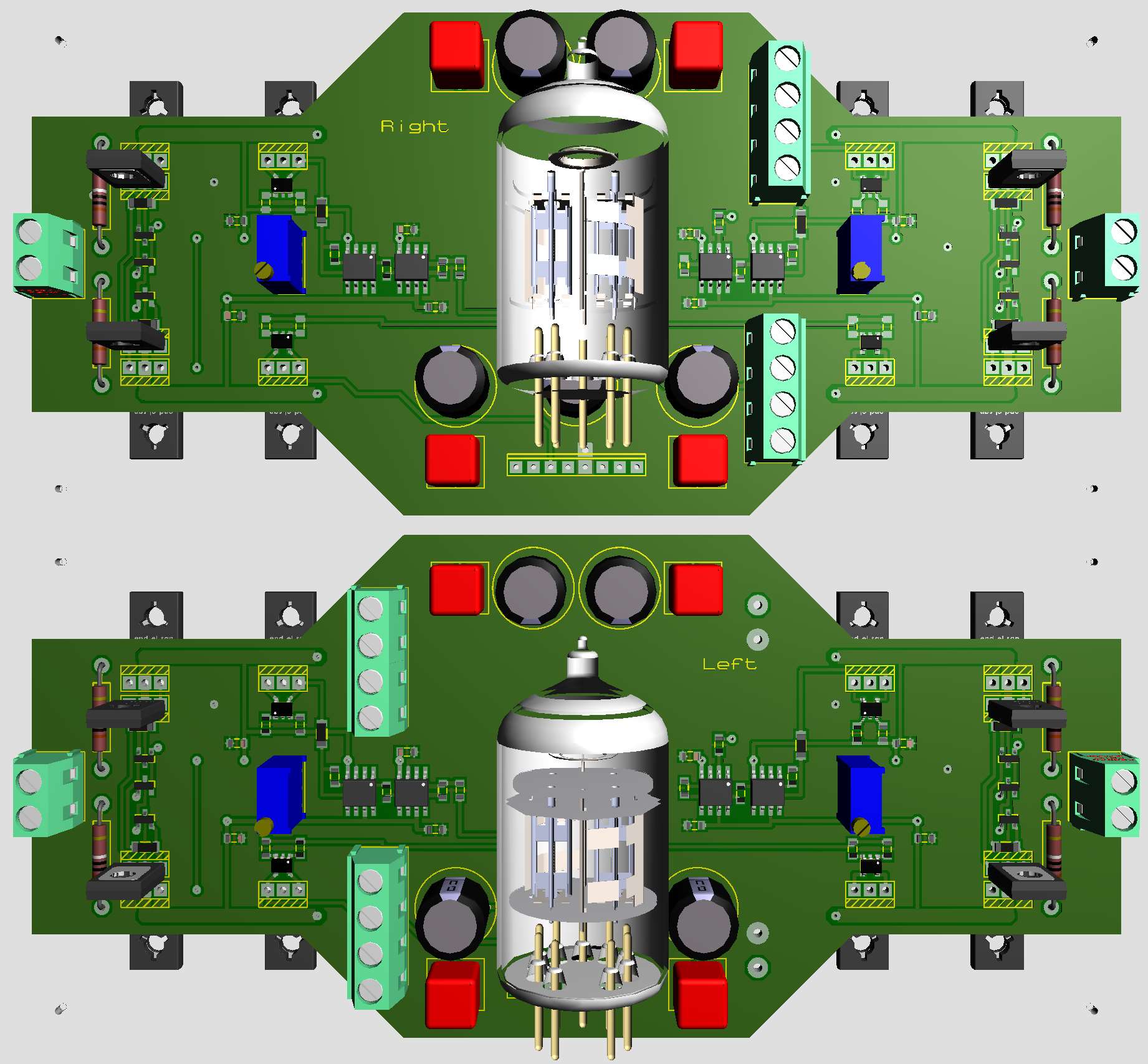
Below is Tube Hybrid schematic. Why op amp U3?
-
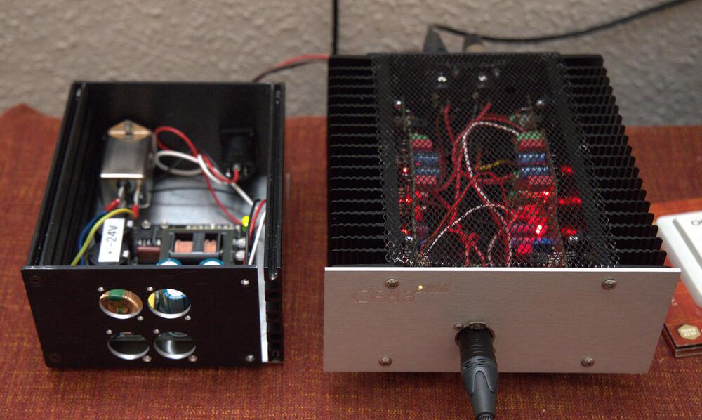
Some folks “over there” seem interested in Kevin’s Tube Hybrid. So, I removed a lot of small components from CFA3smd boards and replaced them with dual triode and double op amp. All according to info I found in Kevin’s library on google drive. It should all fit in the same box as CFA3smd. PSU needs additional voltages, 5- and 100-volt sections and filament for tubes.

-
I'm satisfied with 400V. Started with 500V ten years ago. Reduced to 450V a couple of years ago and now 400V for all my electrostatics, including DIY T2. You might try stn0214. It's surface mounted piece, but it can be soldered in standing on the ksc5026 pads.
-
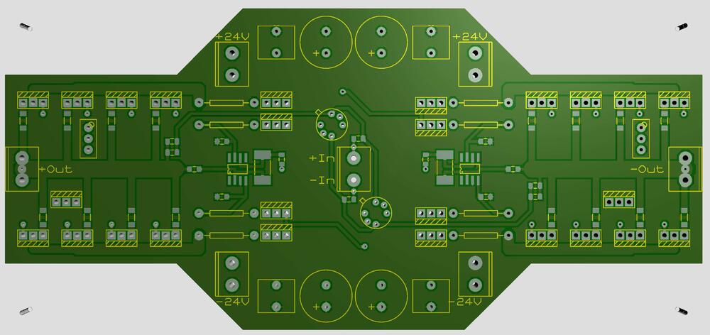
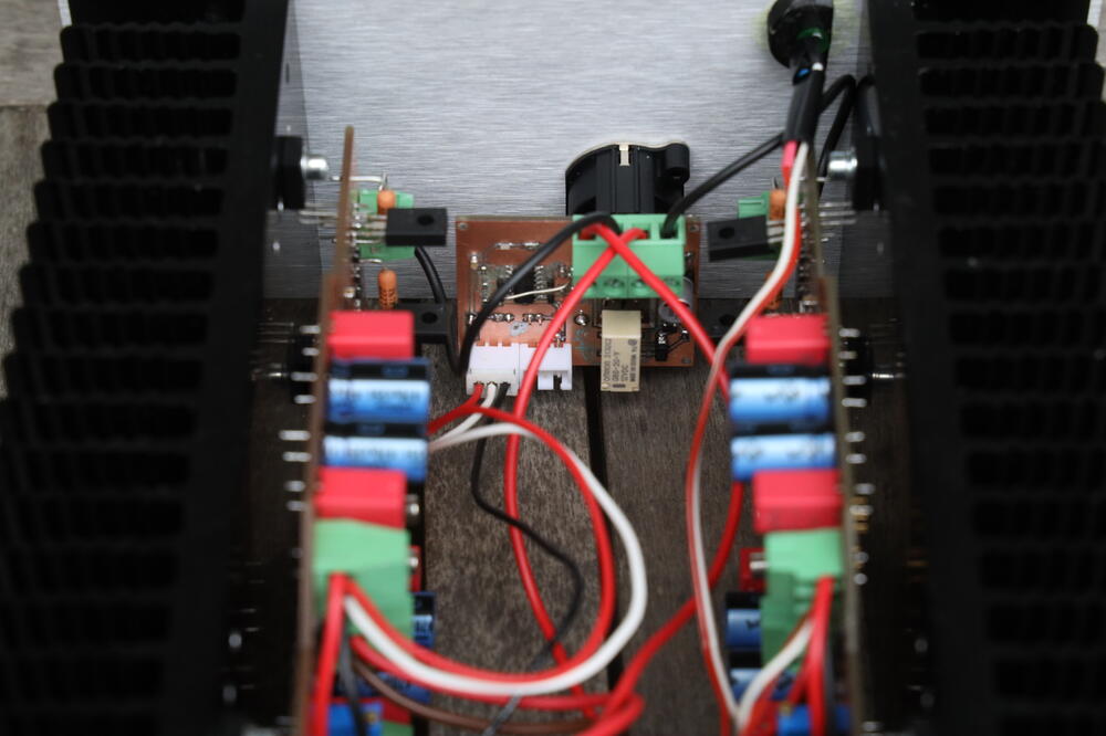
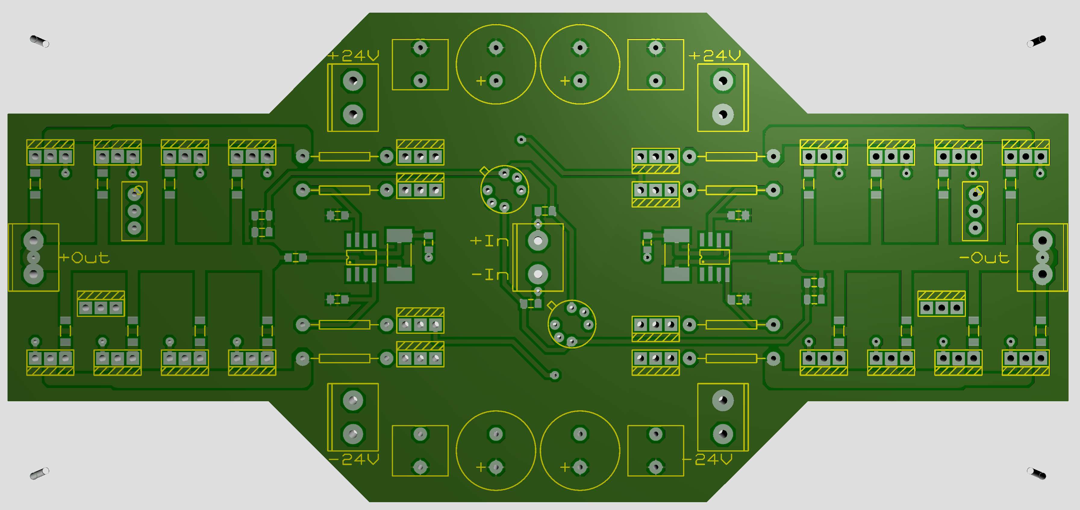
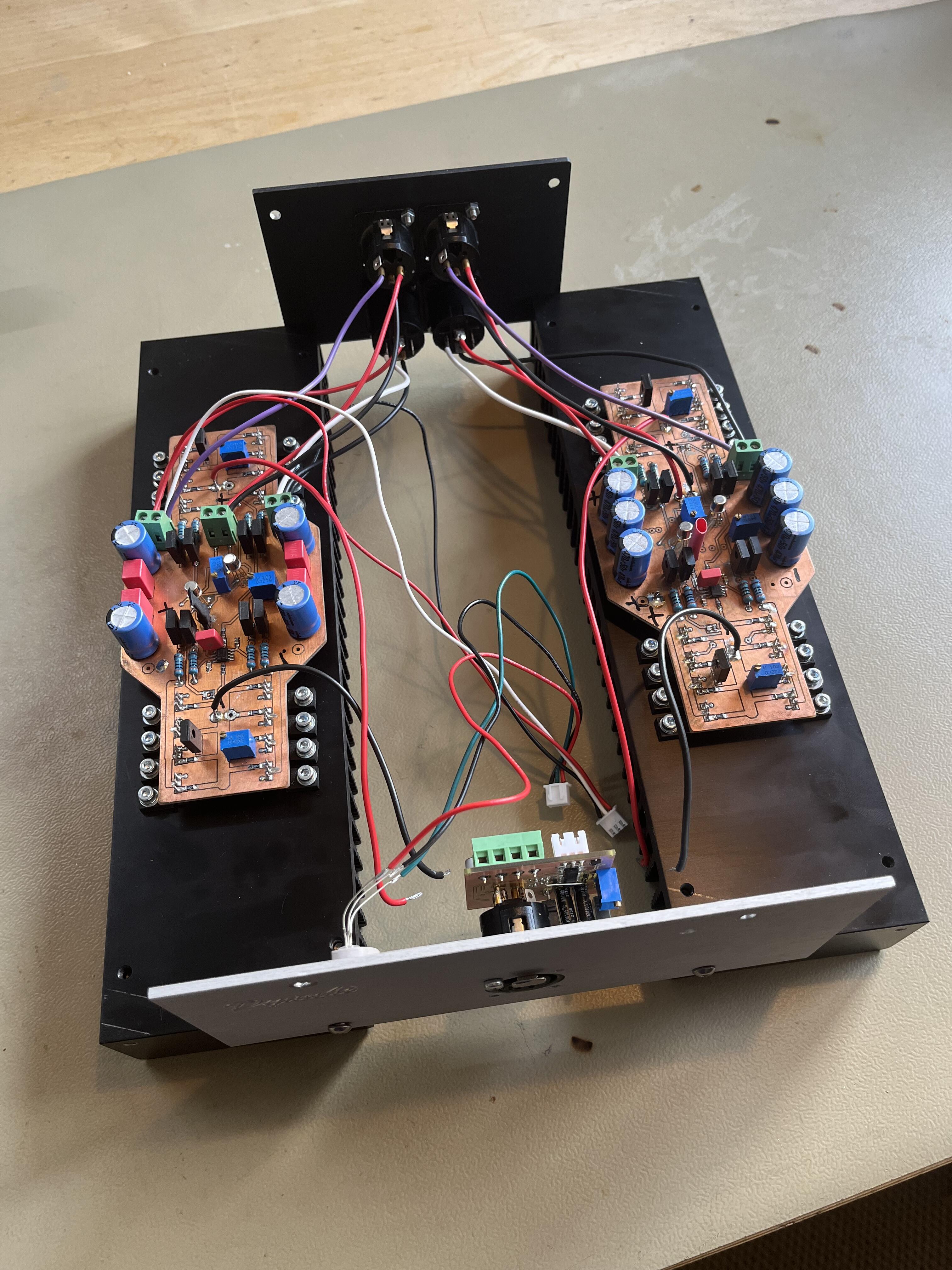
It’s a balanced board. Inputs in center. Outputs at far right and far left. Positive rail at top edge and negative rail at bottom. Dynahi boards mounted to 80 mm x 300 mm heat sinks. Here I’ve removed upper screws holding front and back plates to heat sinks and then “unfolded” for maintenance. To make it possible to unfold the wires are made “to long” when folded and then it looks like a snake nest. This is an Only DIY version, not to be sold... I hope this makes it a bit clearer.
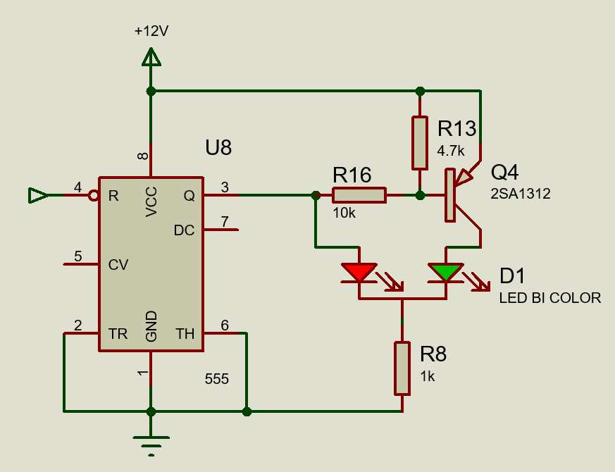
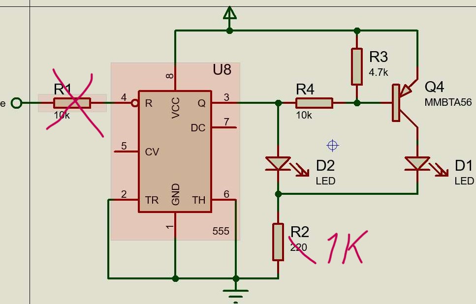
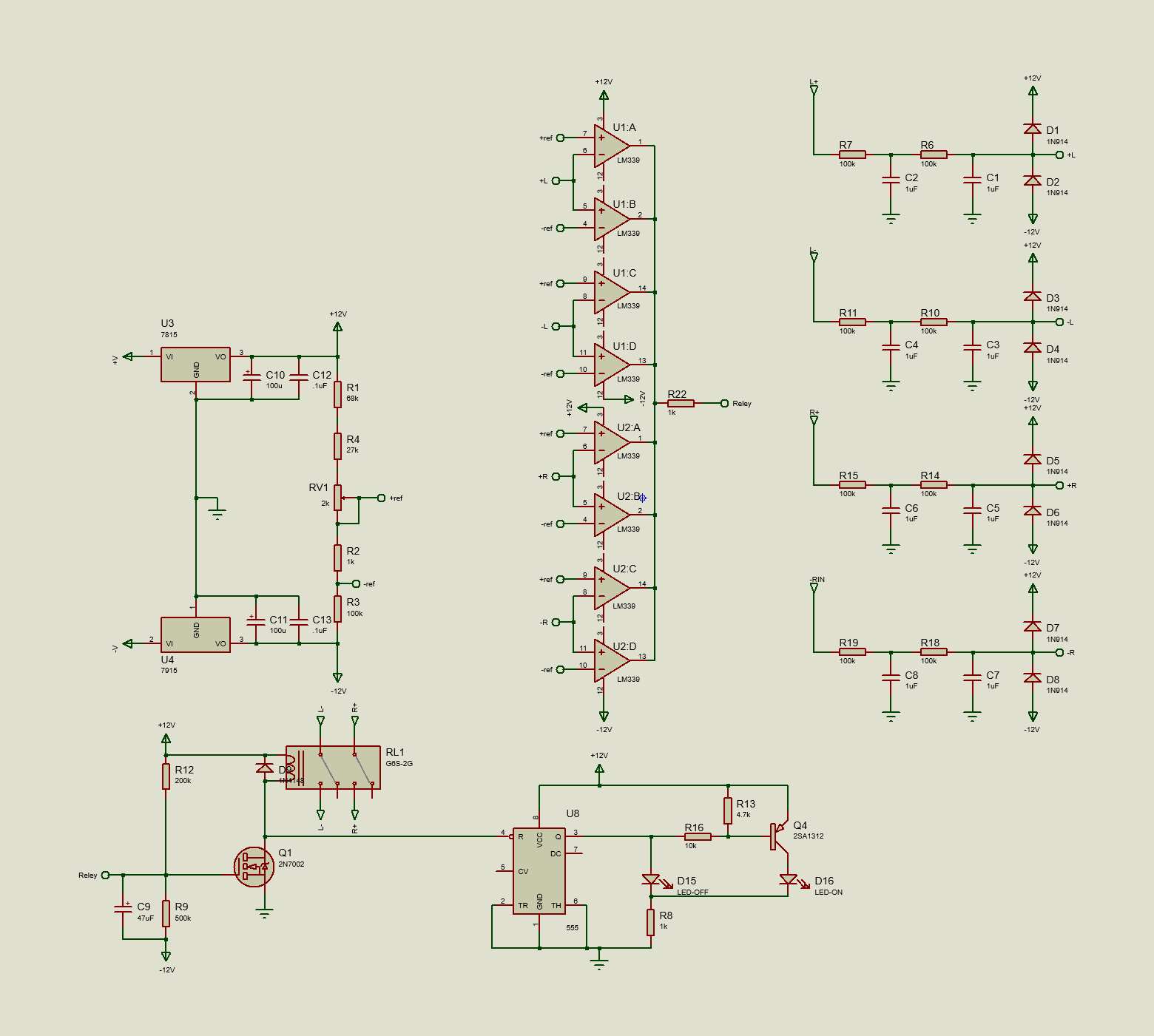
 Seems windows don’t like us. Try click and rightclick you around until you find a way. Alternative go direct to the Gilmore source on Google Drive, click on first link and scroll down to you find protect3.zip.. Lots of good stuff here. Sometimes it’s tricky to find the information you need, but it’s there – somewhere.It’s not very clear in the schematic above (I’m sorry), but D15 and D16 is a bi color LED with common cathode. Below the two LEDs are replaced with a bi color device. The purpose of the 555 is make the LED red when relay is disengaged and green when engaged. This is the way I found to get a simple red/green indicator working.
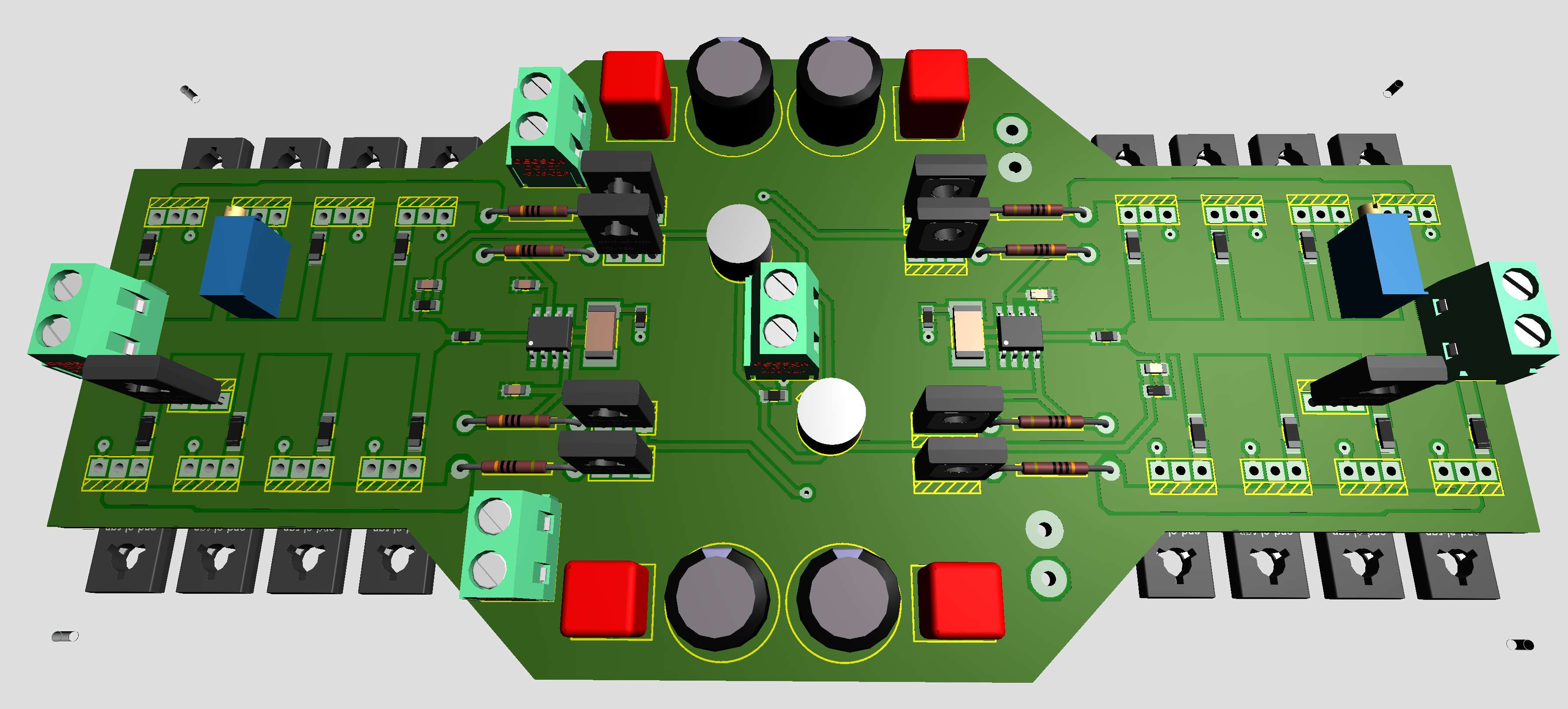
 A slightly reworked “Dynahi smd” board. Balance and offset trimmers removed. Now servo on each side that bring the offsets to ground potential. Bias trimmers moved to north for easier accessibility “in flight”. This is a "solder and play" board. No set up procedures required, except to turn bias trimmers to desired bias. At least that’s the idea.
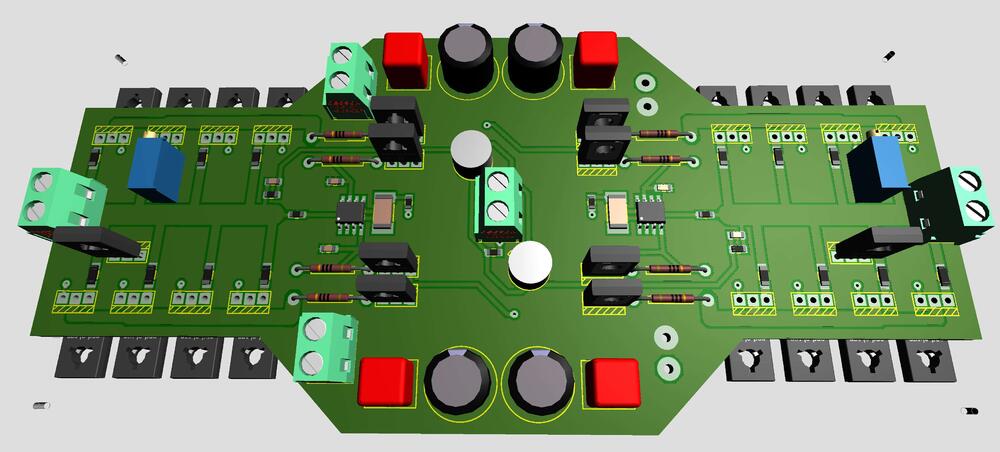 My latest schematics - essentially a copy of the original. See this Protector 3 gerbers by Kevin Gilmore protect3.zip.
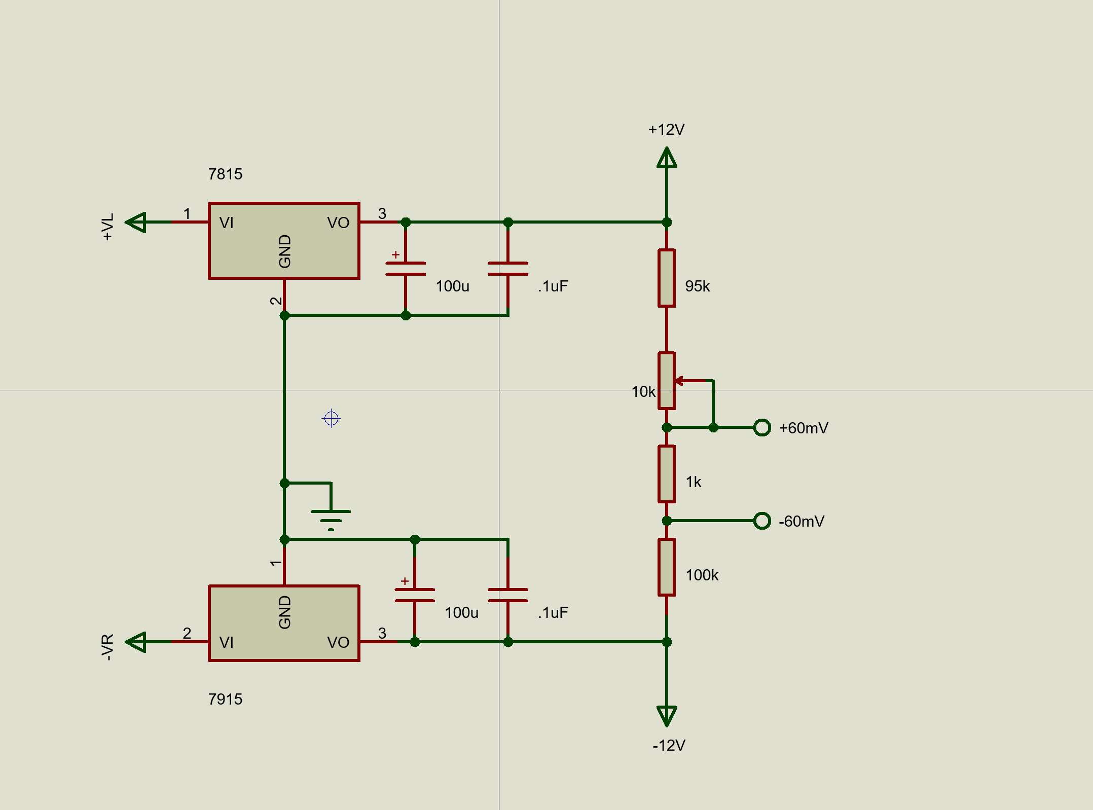
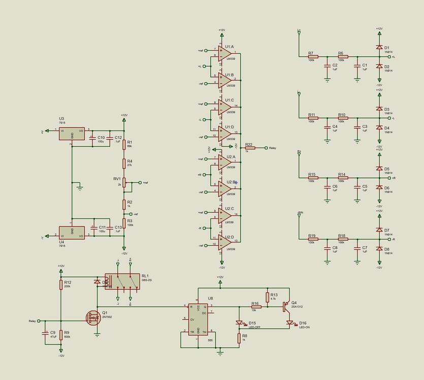 Yes, of course, stn0214. My mistake – I shouldn't rely on memory solely.If it’s ksc5026 in KGSShv style power supply you can probably use stn0216 stn0214 intstead. Solder it standing on the to126 pads (might be to220 pads on your board?). Power dissipation there is something like 40 – 60 mW, I think.During the last weeks I’ve built a few versions of the headphone protector. One small problem is voltage regulators, 7812 and 7912. Output voltages might differ more than 100mV from “specified “. 7812 at +12.1V and 7912 at -11,9V will move intended references 100mV. To tackle the problem, I made this resistor string. With above resistor string I can handle any deviations of the voltage regulators up to 200mV. If you want something else than +/-60mV trigger points, change the 1K resistor. 2K instead of 1K gives you +/-120mV. I’ve enjoyed working with this protector project a lot. Thanks for designing this Headphone Protector, Kevin.
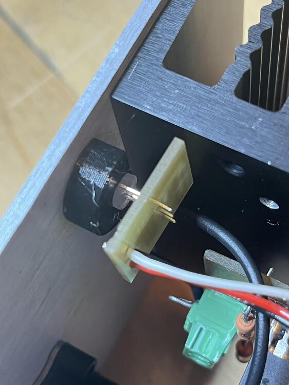
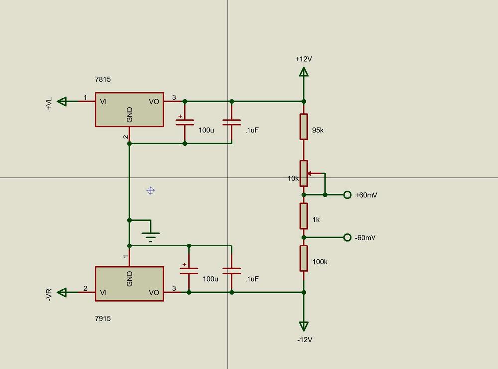 Nice board.Next build – remove R1 ( don’t understand why I put it there – maybe because I’m an amateur) and R2 value is far too low, unless you want 40 mA through LED, so I switched to 1K. Small board 19mm x 15mm with the 555, a small PNP , three resistors and of course the bi color LED. Works perfect.
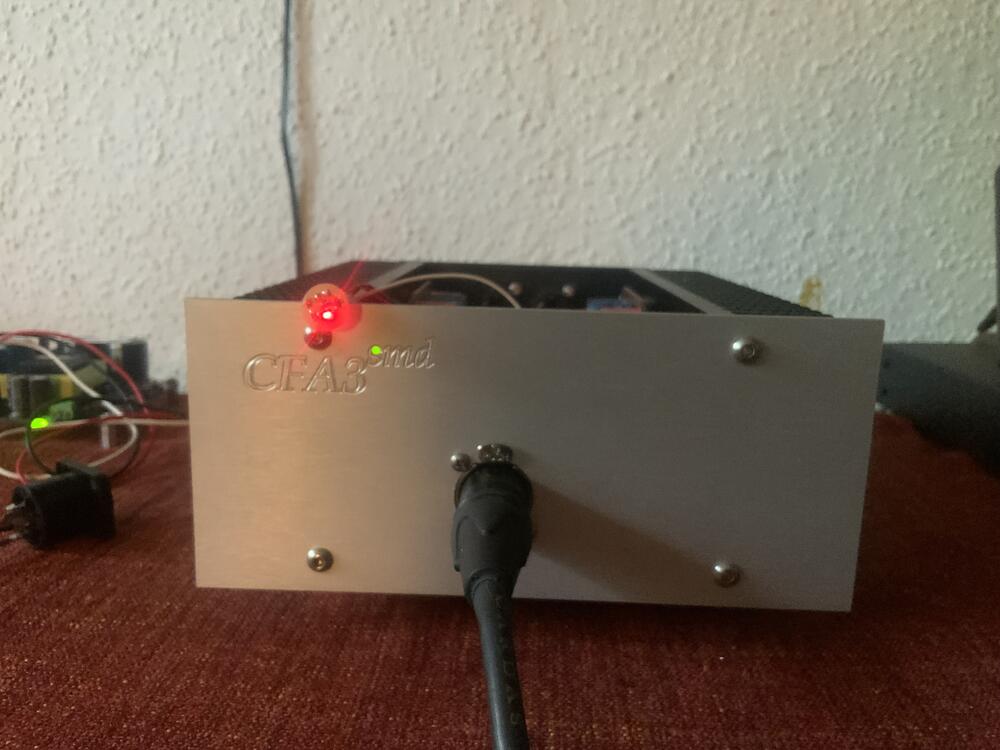
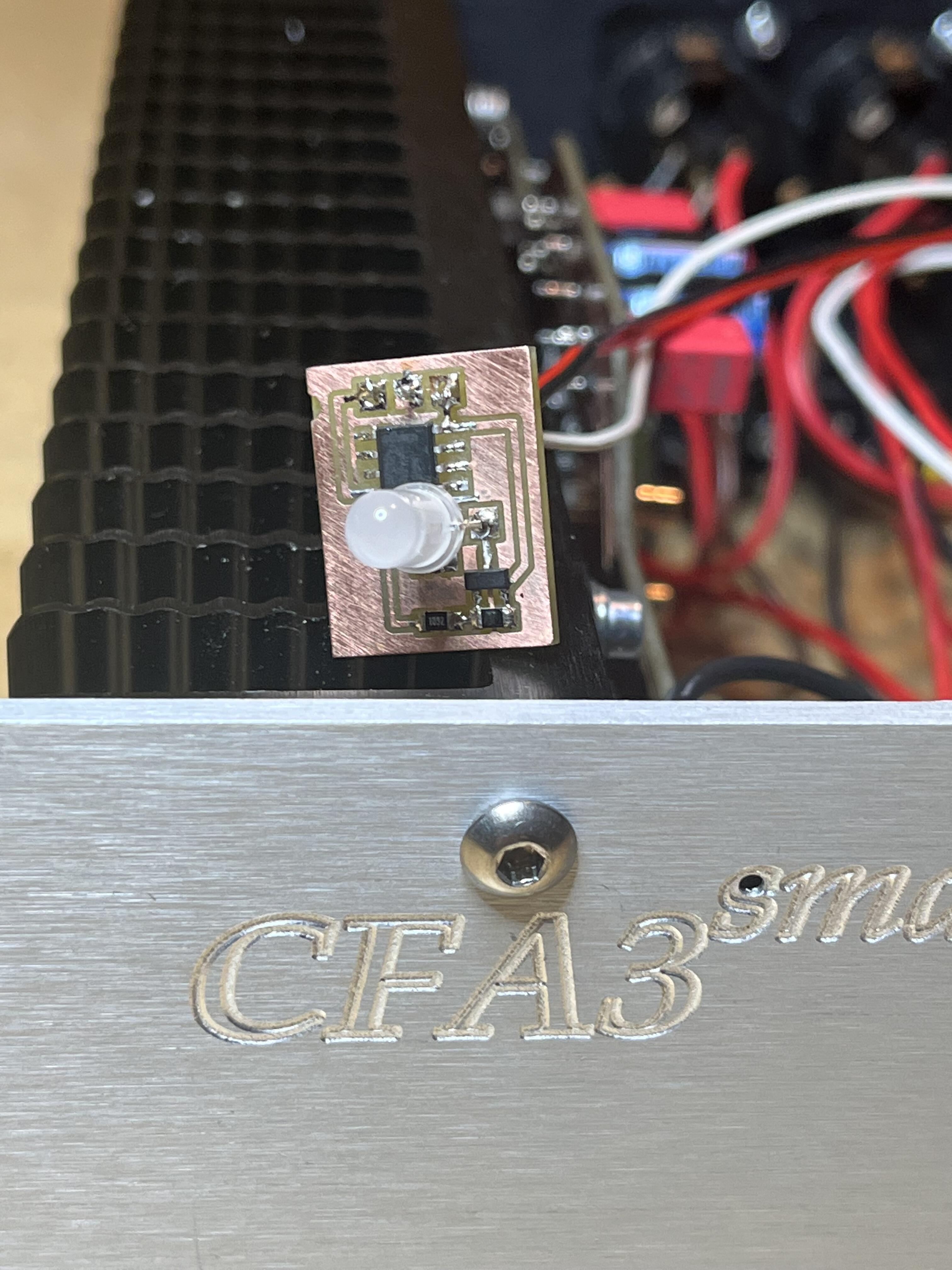
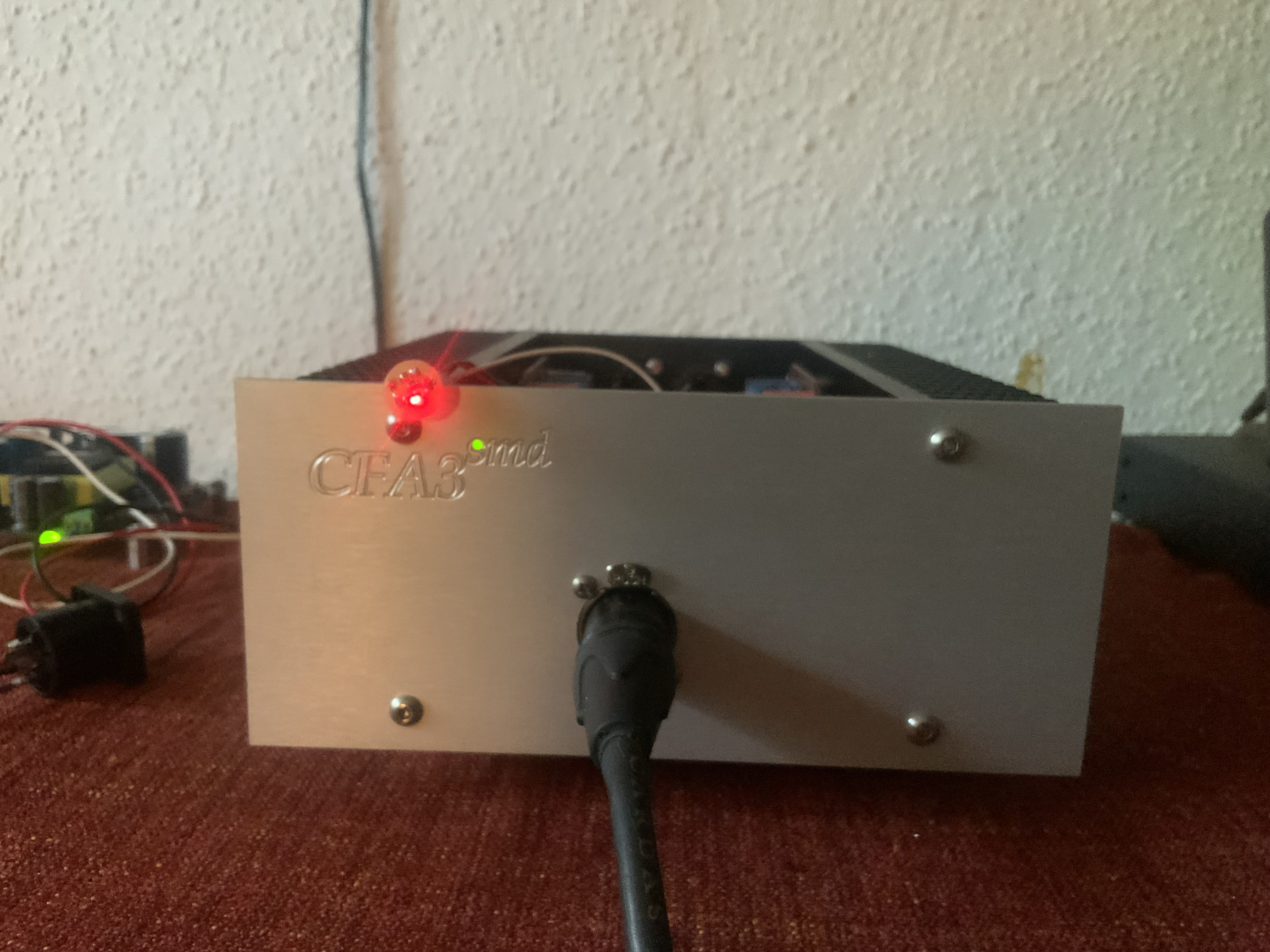
Nightly build Red LED indicates disengaged headphone. The green LED indicates power is on. Here red is out and headphone is connected. Next build… …a bi-color LED to replace the two above LEDs.
Nice board.Next build – remove R1 ( don’t understand why I put it there – maybe because I’m an amateur) and R2 value is far too low, unless you want 40 mA through LED, so I switched to 1K. Small board 19mm x 15mm with the 555, a small PNP , three resistors and of course the bi color LED. Works perfect.
Nightly build Red LED indicates disengaged headphone. The green LED indicates power is on. Here red is out and headphone is connected. Next build… …a bi-color LED to replace the two above LEDs.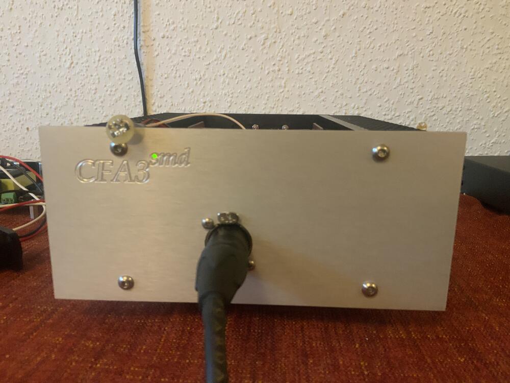
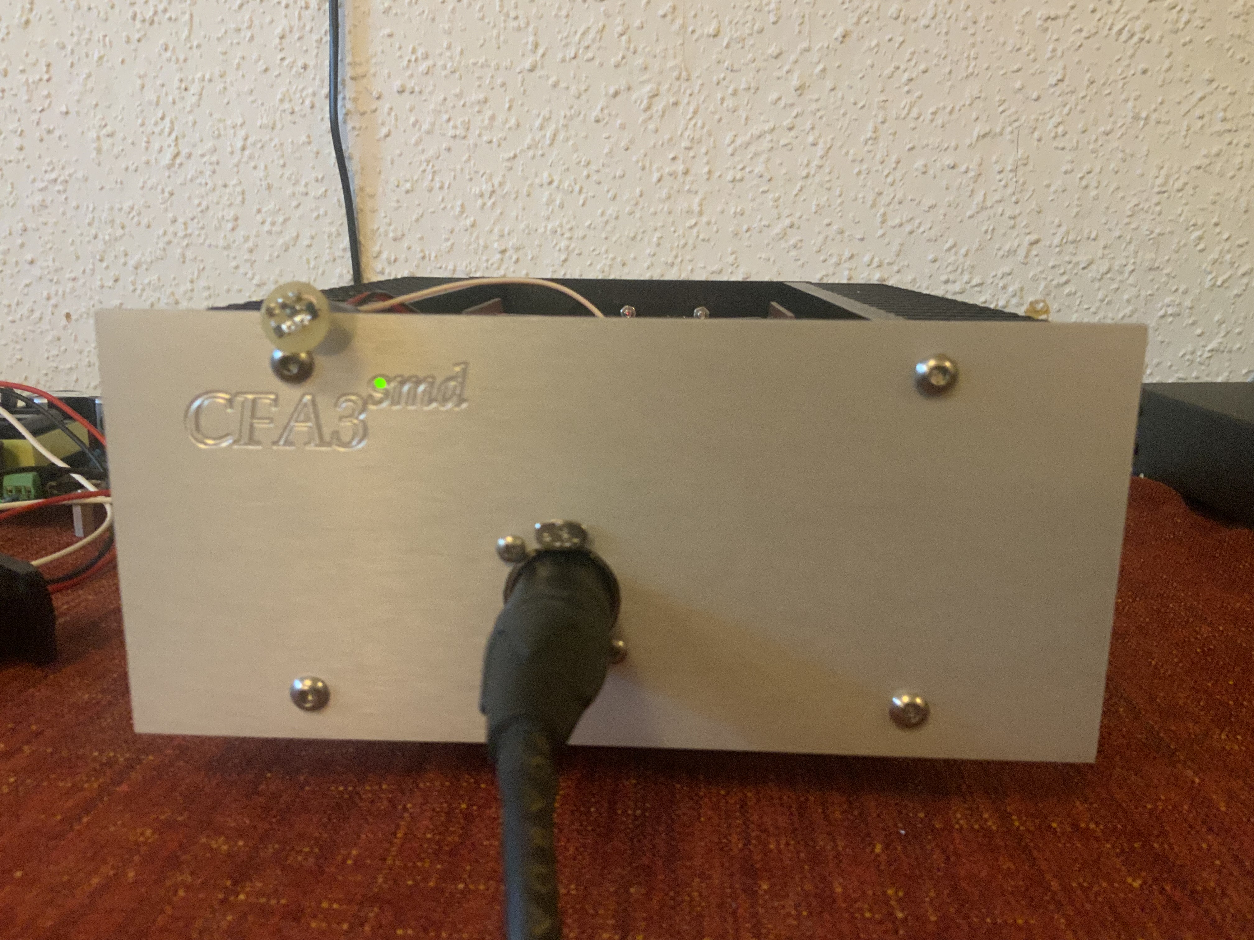
 Headphone protector installed and working. Delay time is 15 seconds, and it disconnects when offset is more than approximately +/-70 mV.
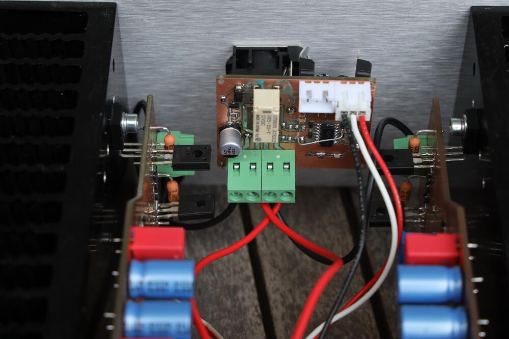
 Yes, very much.


Important Information
By using this site, you agree to our Terms of Use.