JoaMat
-
Posts
1,546 -
Joined
-
Last visited
-
Days Won
16
Content Type
Profiles
Forums
Events
Everything posted by JoaMat
-
Happy Birthday!
-

JR Audio amplifiers aka zero fucks are given - caveat emptor
JoaMat replied to spritzer's topic in Headphone Amplification
Deleted! -
Yesterday I Had The Blues - The Music of Billie Holiday José James

-
I think you are right. I’ve used 2SK879 in one T2 battery since several years without any issues. From datasheet 2SK208 and 2SK879 look quite similar.
-
Me too like schematics. I believe this goldenreference.pdf reflects goldenreference6.zip version.
-
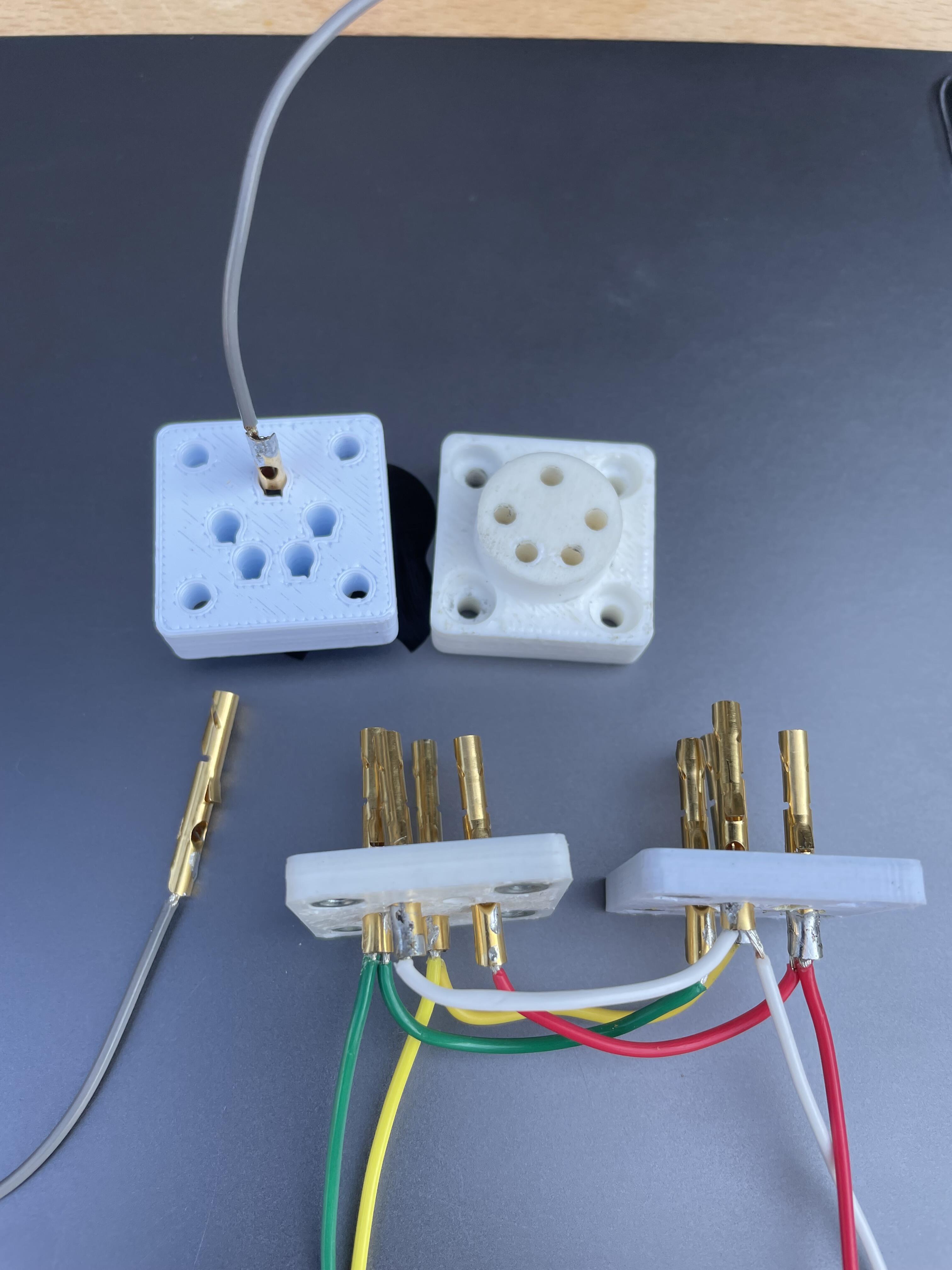
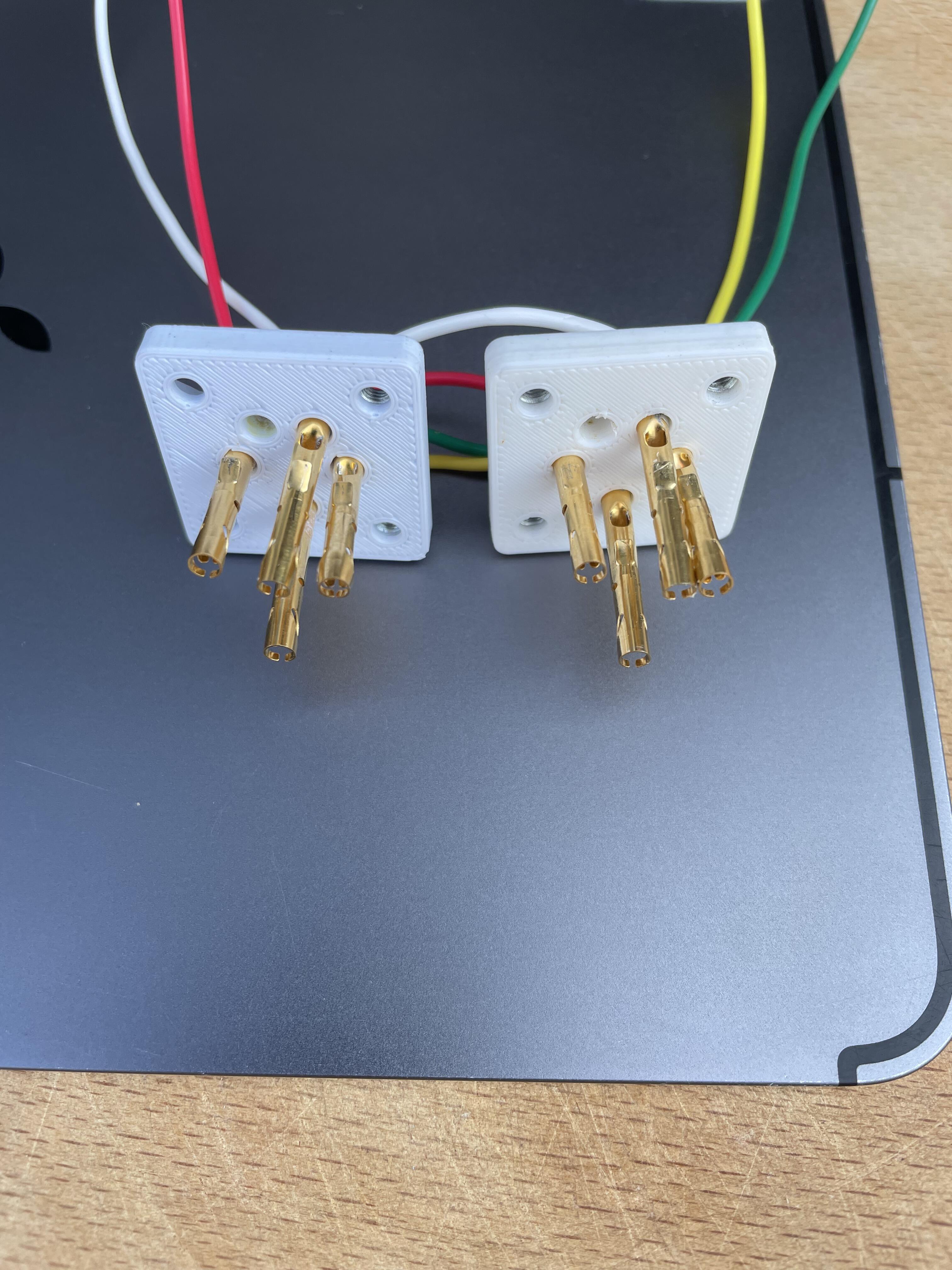
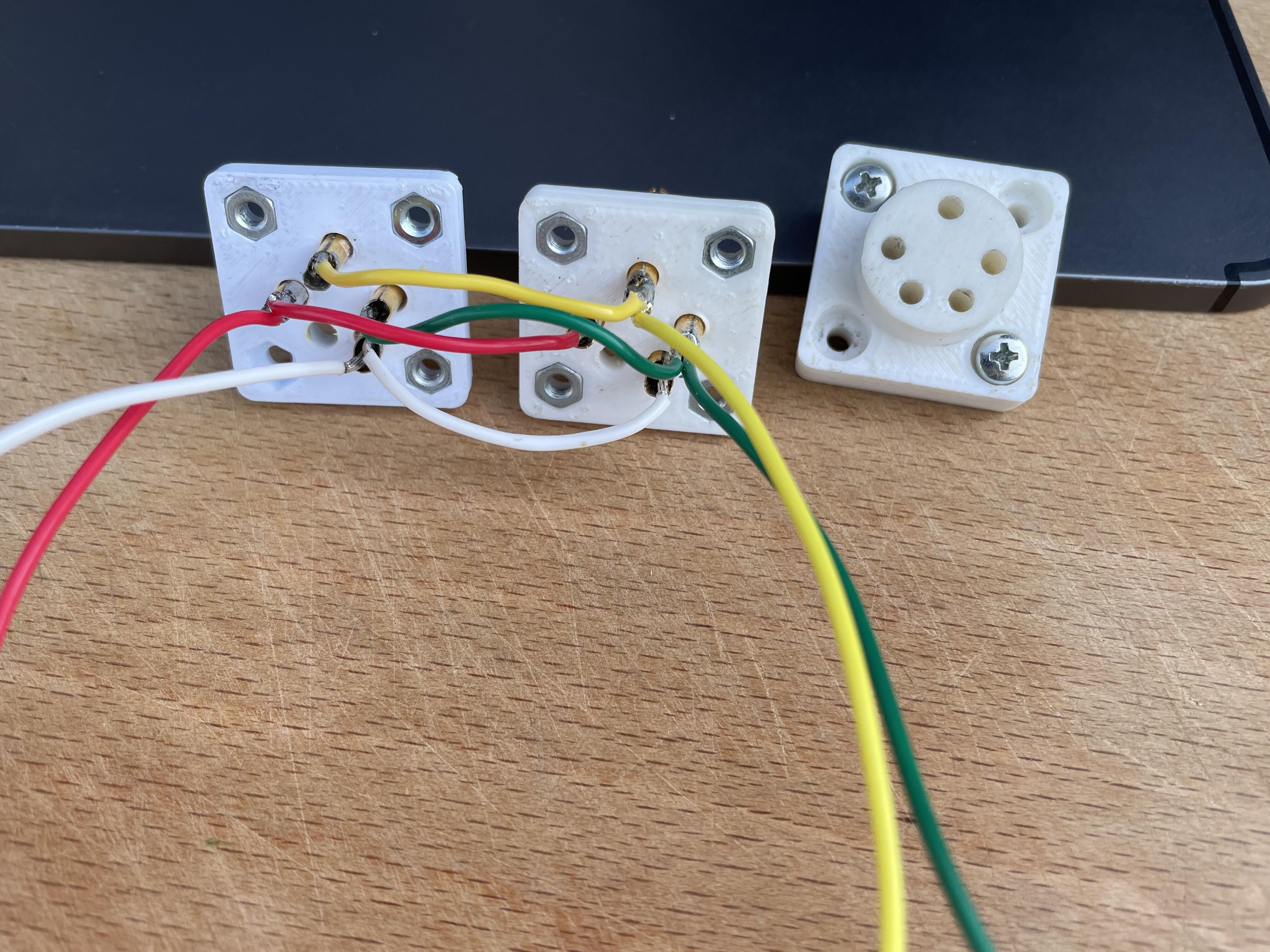
Here are the connectors disassembled. Pins are from Neutrik NC3FD-L-B-1. Take a metal saw and make a cut so you can bend up the outer metal housing. Then pins can be removed from inner housing. I would have prefer Teflon over 3D printed. I haven’t figured out how to mill it out though, but I managed to 3D print something usable.
-
Thanks for dielectric values of PLA and PETG. Them in picture above are PETG but I’ve also used ABS which also works. I assume you can use PLA as well, but both PETG and ABS melting temperature are a bit higher than for PLA which might be an advantage when soldering wires to contacts.
-
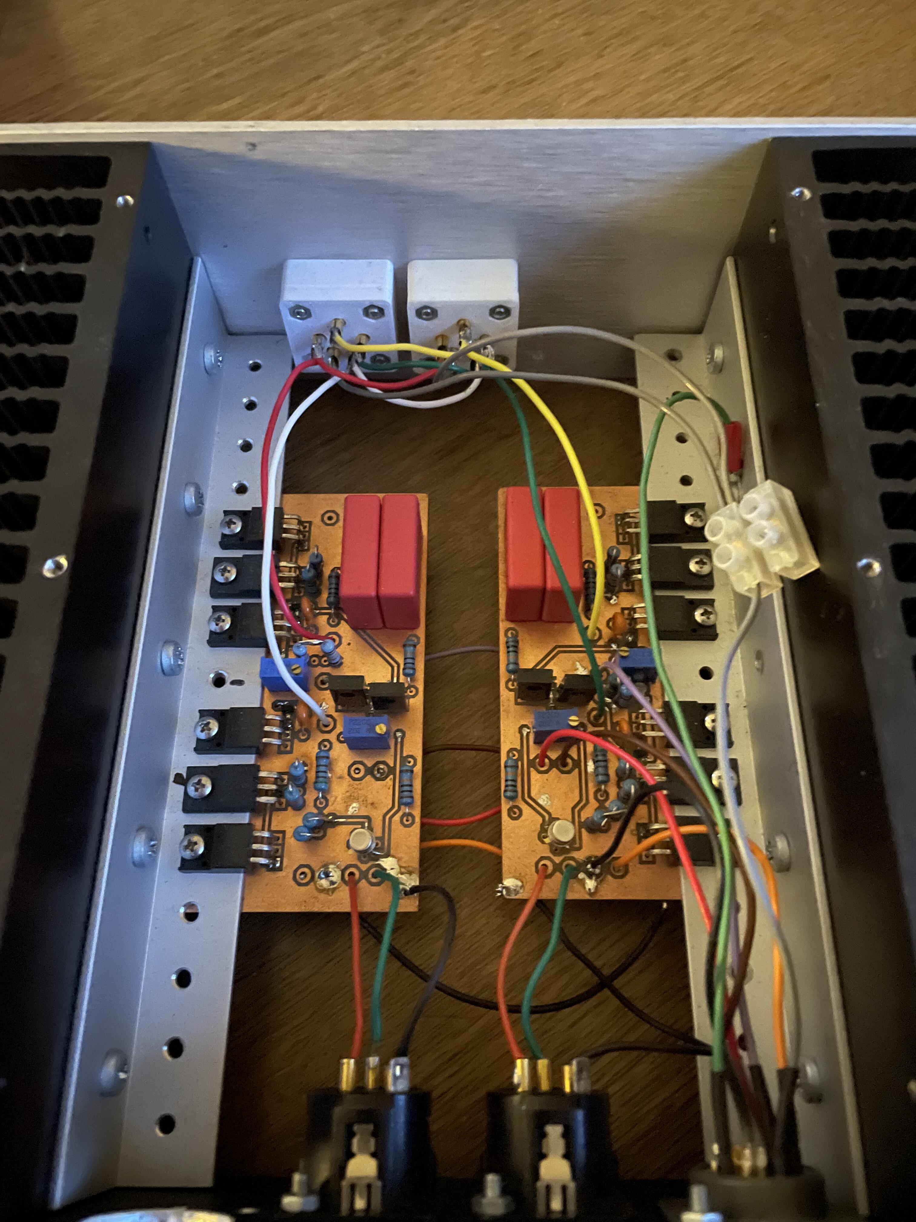
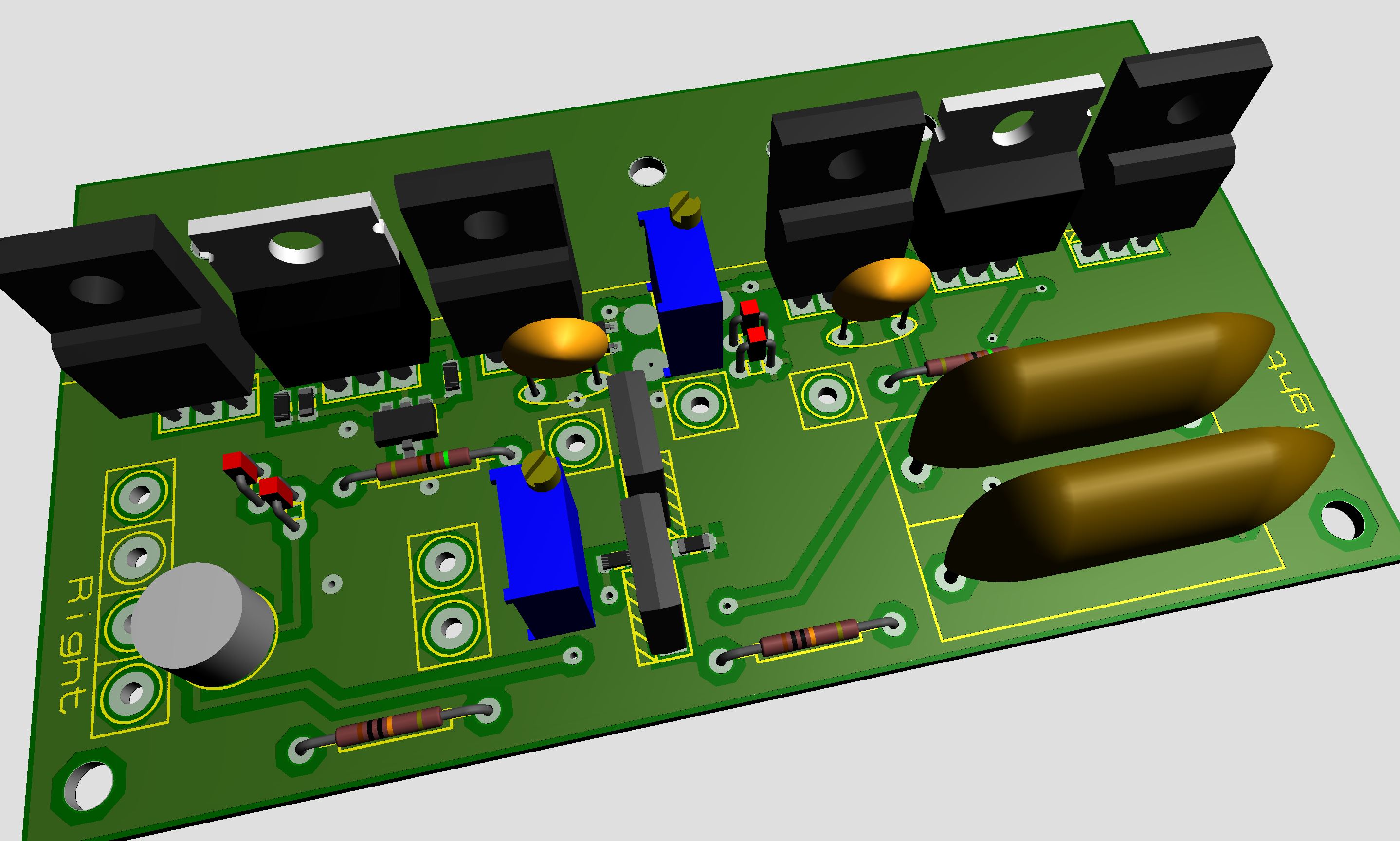
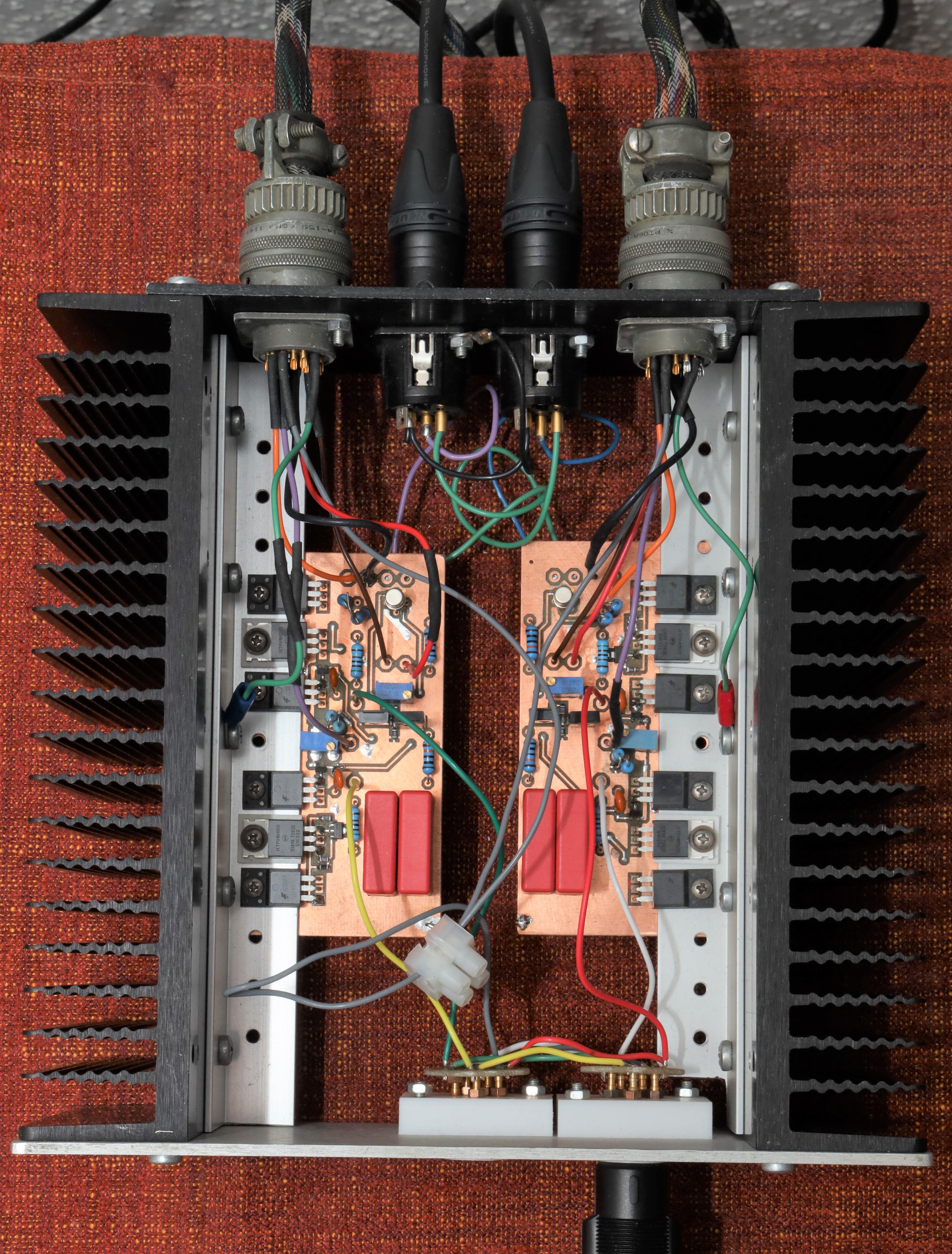
As most other DIYers I use Teflon Stax connectors with a small PCB. But on below amplifier I use 3D printed connectors with female golden contacts from Neutrik 3 pole XLR. And they seem to work really well. On heat sinks are 4 groups of c4686/a1968/c4686.
-
Thanks guys. Yes, external PSU (T2 PSU with some addons). Maybe one can’t call it a Carbon since output stage is formed by NPN BJT - but else it’s similar. I think current is like 10mA. 300R emitter resistor and two LEDs in series. With +/-400V the heatsinks are “hand warm” and you can probably double the current.
-
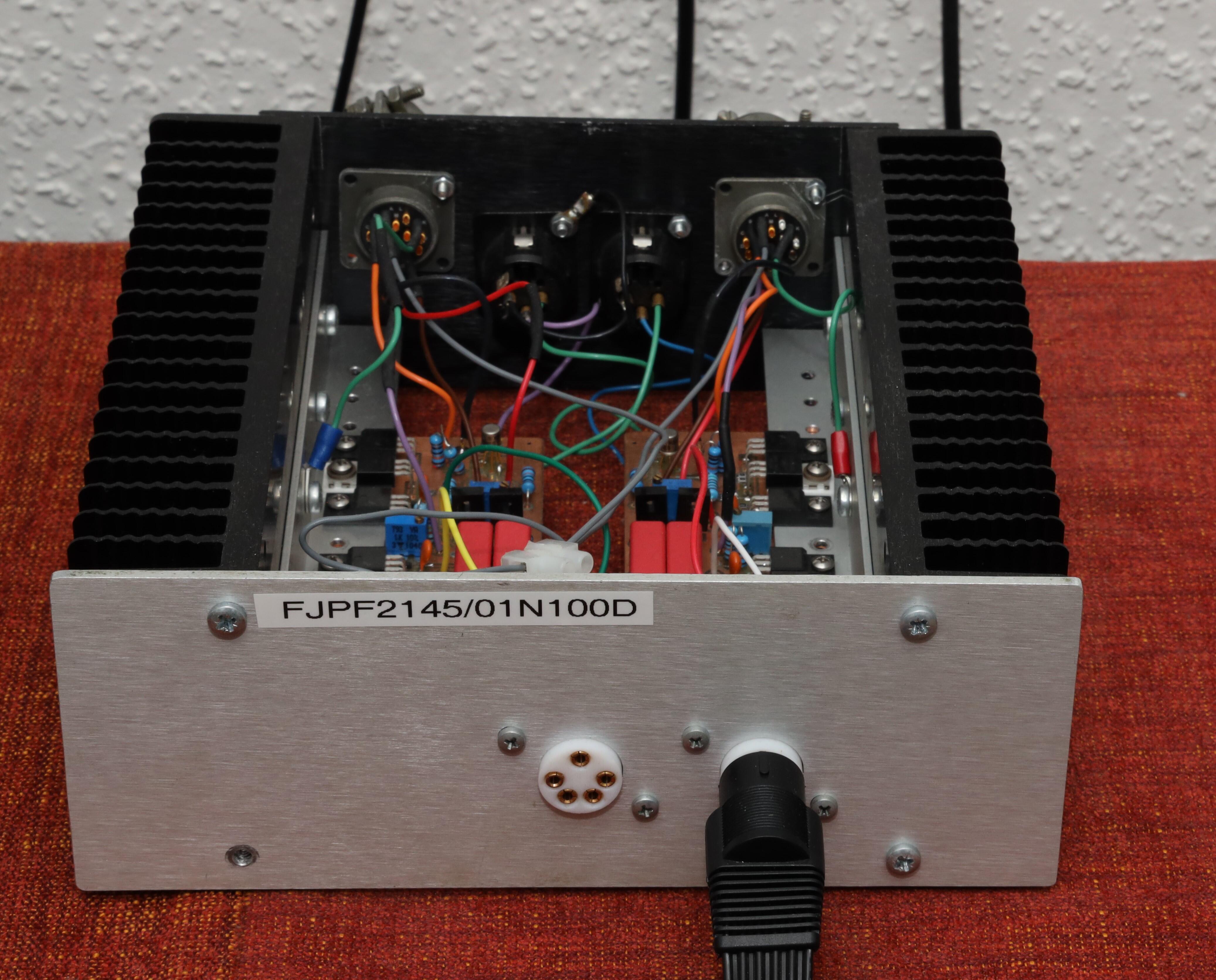
Has been in service for a few months now. Sounds alright.
-
https://www.svtplay.se/video/31776463/jazzsommar-karl-olandersson-kvartett?id=KyE3oPV Should be available worldwide for the next 24 hours. From Sweden but Jazz is universal.
-
Nice, Kerry! Now I get it - and the three pins (-, +, o) and all vias visible on the other side make sense even to me.
-
Thanks Kerry, for internal picture of and info about your T2. It’s always very inspiring see your work. I assume the four small boards, one at each big tube, are CCS for the two LEDs on main board at respective output CCS. They must differ (schematically) from the original design, mustn’t they? Do you mind tell us what the small boards look like?
-
Nice build indeed. I like the minimalistic – just a single Stax connector in the front and power switch in the back.
-
Happy Birthday, José!
-
Thanks James. It certainly looks like dn2540 has been flipped. After consulted the schematics and checked the board I do believe the silkscreen is correct.
-
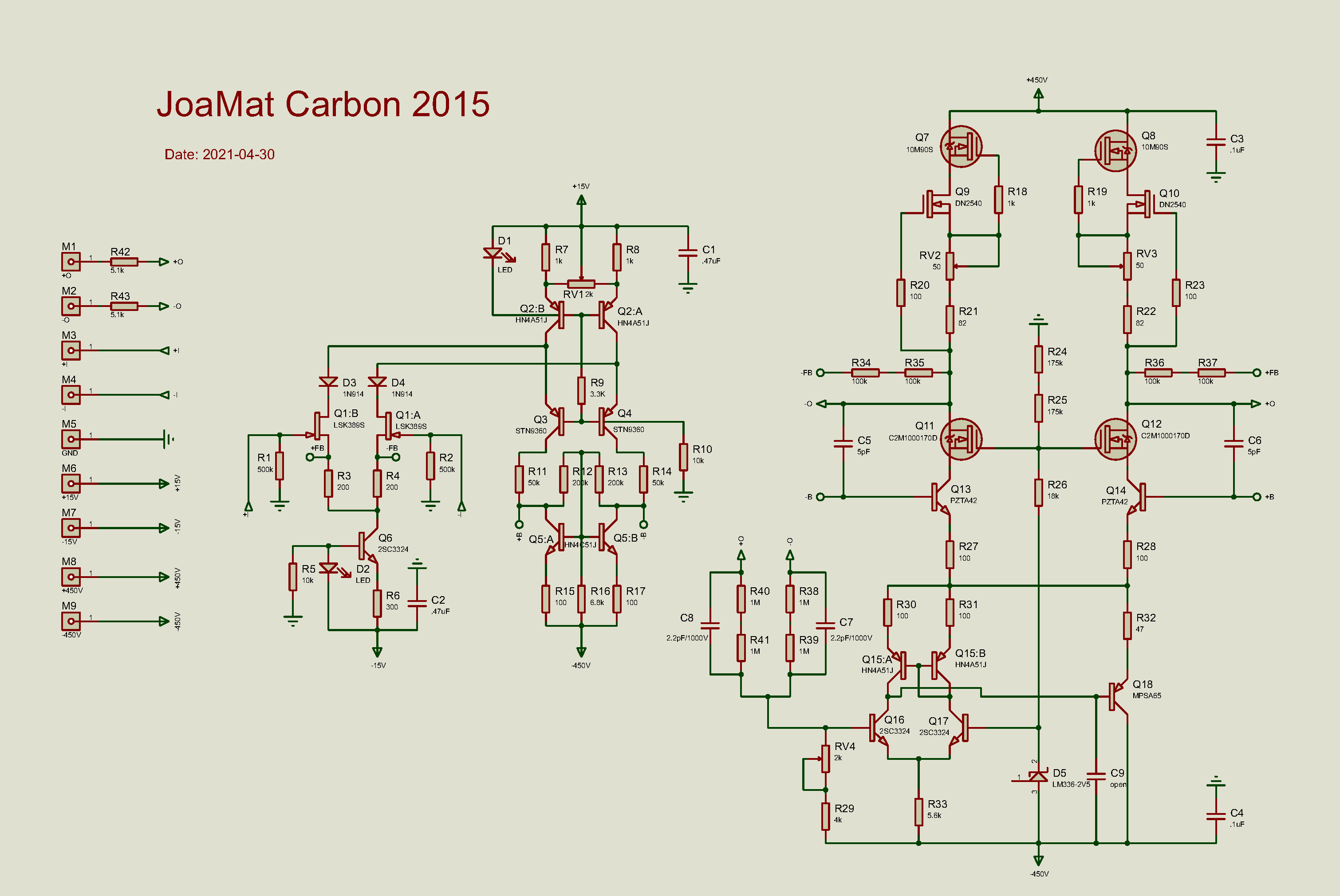
Take look at the schematic. The offset servo can’t be disabled!
-
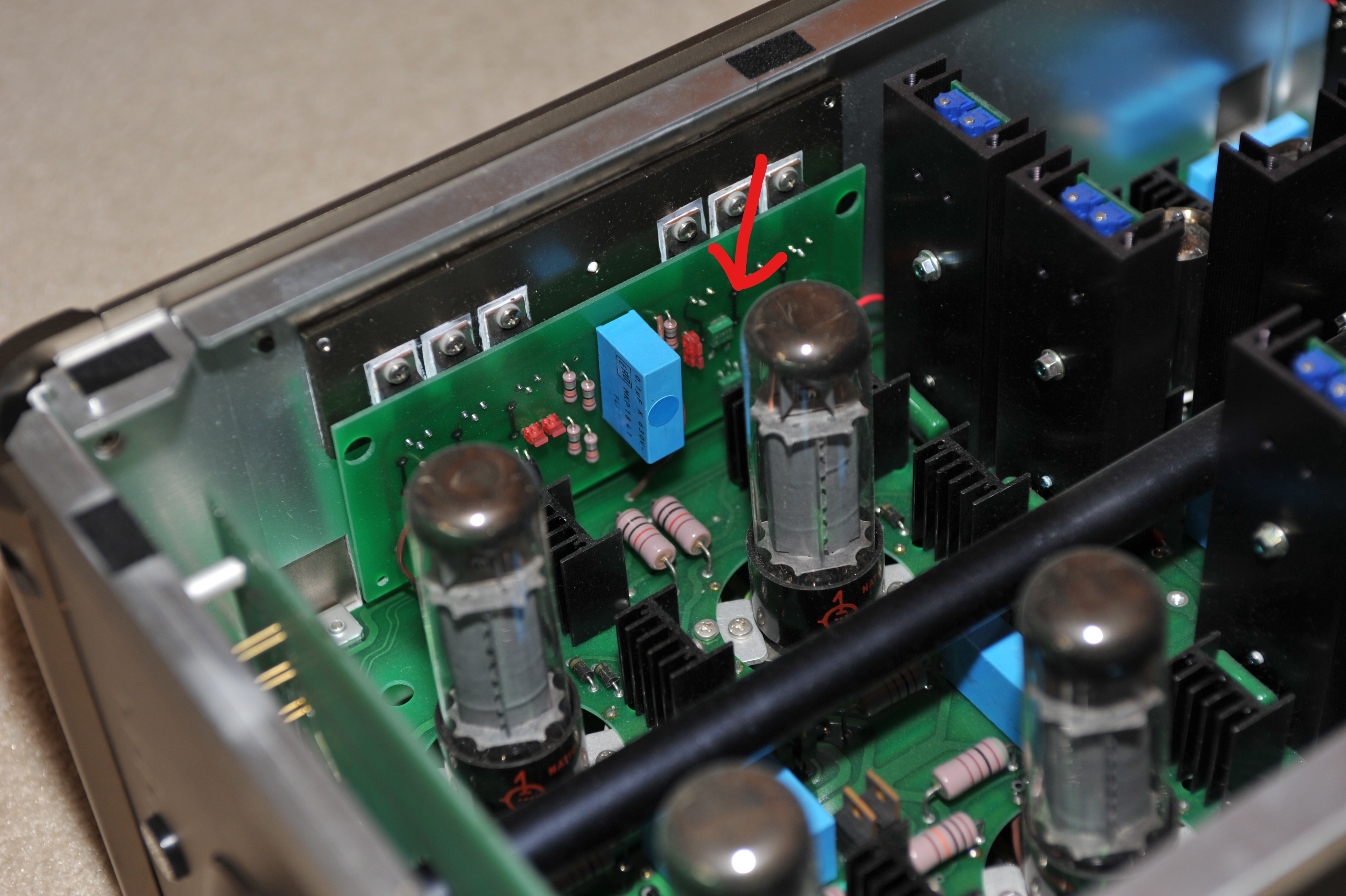
Nice work, Sebtdi! Here is a schematic for the amplifier boards Sebtdi and sweetleaf are using. Main difference to above schematic (kgsscarbonproduction.pdf) is the offset servo. The adjusting procedure for this is like any other Carbon. Balance is set by the trimmer close to the LED and offset balance is set by the trimmer close to output connector. For setting the output current use the two most outward trimmers. It might be bit tricky to measure the voltage cross the resistor (R21 and R22 in your case) on a live amplifier. Myself, I always check the current with help of a low voltage supply and a multimeter in mA DC mode cross the constant current source. Below sorenb tells how to do. I guess a 9V battery for low voltage will work just fine.
-
Nice progress, starcat. Some builders put LEDs on the other (tube) side... Also, putting battery 22K resistors on the tube side elevated half an inch makes it perfect for using clip leads when setting the voltage to 6.55V.
-
Great! Looking at your measurements of ref102 I suspect you might have the problem there. You should have a potential at Out (pin 6) of 10 volts above -562V - that will be -552V and not -532V. You have a spare ref102?
-
May I suggest a diode test comparison Q20 against Q15 to exclude the 2SC3675? If not already done.
-
Familiar with the diode test method? See this post. Seems the regulator isn’t doing anything but passing all unregulated voltage through. My bet is on a faulty mosfet... or something else.
-
Happy Birthday, Kerry!
-
Isn’t 2SA1413 a smd TO-252 something? Looking at picture below it seems Stax used something like that in the output current sources in SRM-T2. You might consider KSA1156 for 2SA1486 on heat sink and in batteries. Reduce high voltages to +/-400V and you can use KSA1156 in the output current sources as well. As I see it reducing the voltage is beneficial without drawbacks. I’ve used STN9360 in batteries and even in output current sources. Bend outer pads slightly outwards to fit holes and solder them in standing. In current sources they will idle at 1/4W.