


JoaMat
High Rollers
-
Joined
-
Last visited
Everything posted by JoaMat
-
Did this tonight
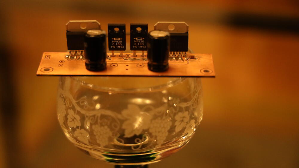
-
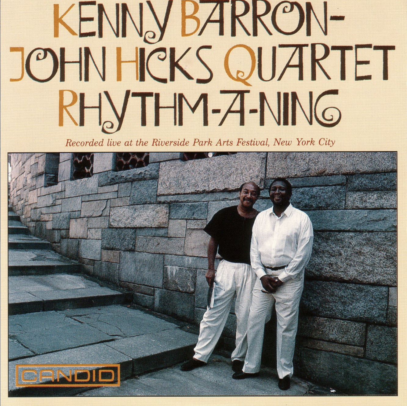
LES SIÈCLES, FRANÇOIS-XAVIER ROTH Sur instruments d’époque / On period instruments

-
Anyone out there have built the raal opamp driver besides justin? I’m interesting and I guess other people are as well in the outcome and thoughts about the driver.
-
look - terminal blocks...
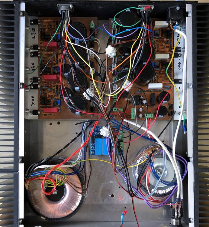
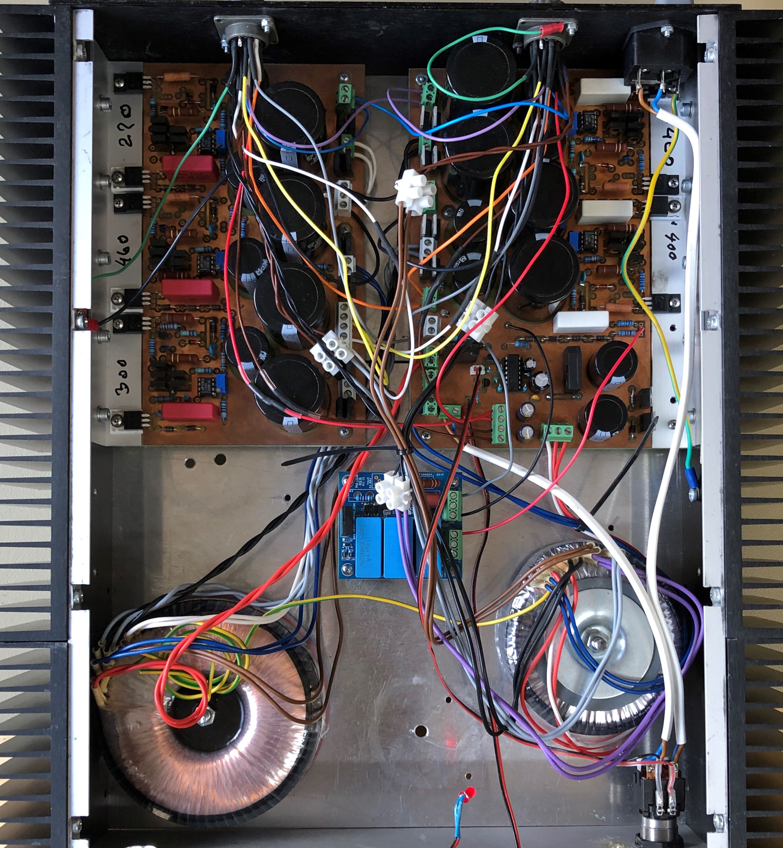
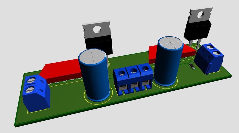 B - (((R8+R9+R10)/R7)-1)*VrefTo me it sounds that you built yourself a nice amplifier. Enjoy.At the power supply schematic – shouldn’t D12 anode be connected to the cathode of D1?If you remove C2 (0.1uF cap) I guess it will possible to set BIAS to 230V with help of the 1M trimmer.Thanks. Who made them - Mueller-r.. something?Nice power supply. I can’t read the labels on trafos. What are their specifications?Here is my T2 power supply, now with Pro Bias Maida regulator style. The small board with three blue filter capacitors is the 21st Century Maida Regulator by Tom Christiansen producing 580 volts after change of resistor. The Maida regulator replaces the 10m90s current source with Zener string and filters. I feed the regulator with unregulated 660 VDC. Only 5.1M resistor on psu board is used. Works great. P.S. still need some wire clean up… will probably never happen
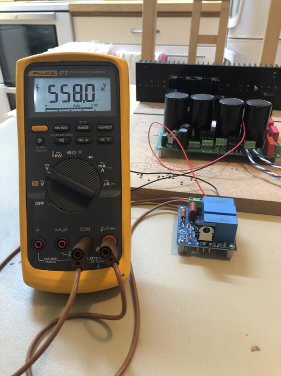
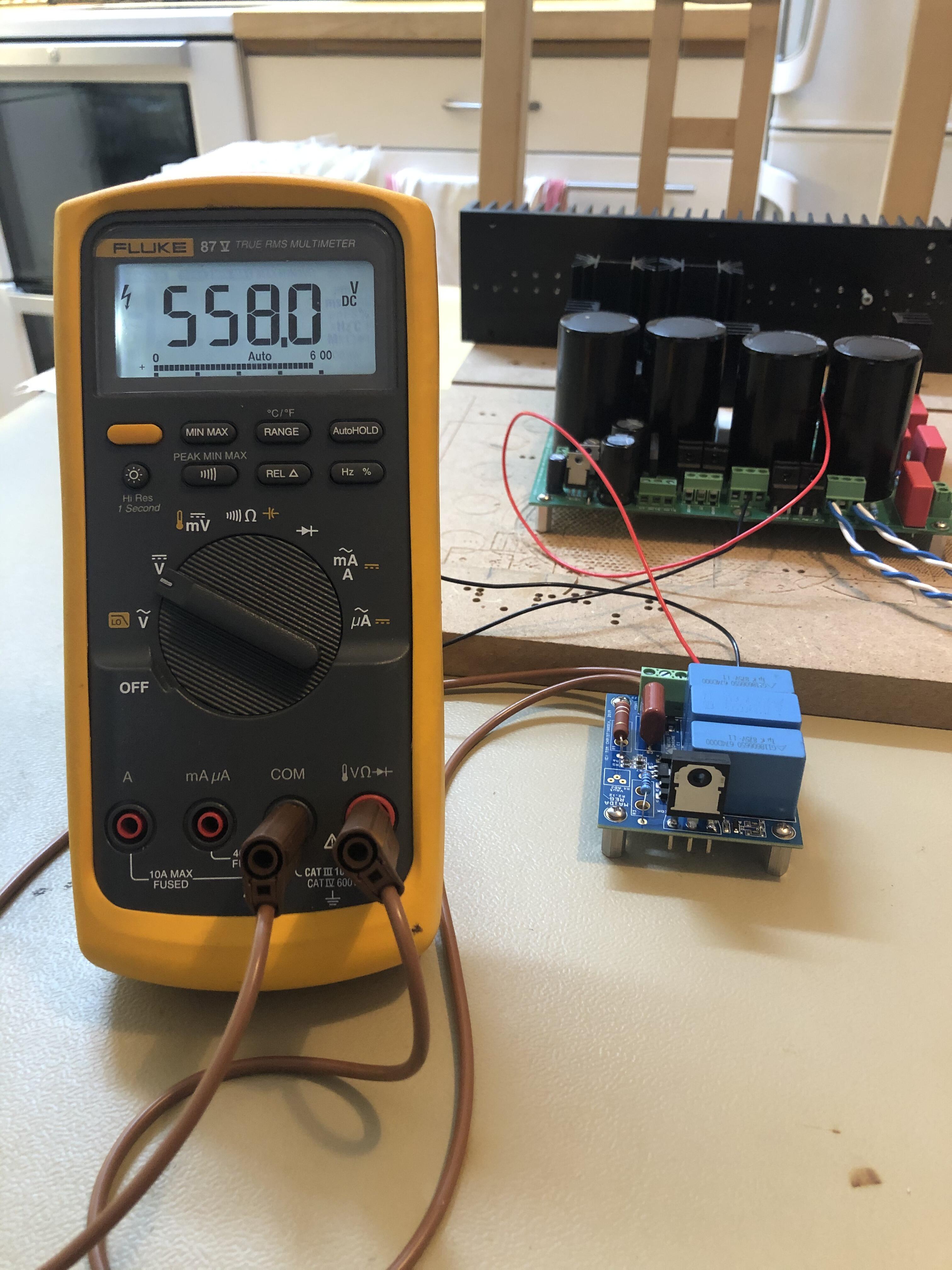
 My condolences, Jose.Tested the 21st Century Maida Regulator as a Bias 580V regulator. Got 558 V with the components I had at hand. It takes about 15 seconds to reach desired voltage. To be continued (maybe).
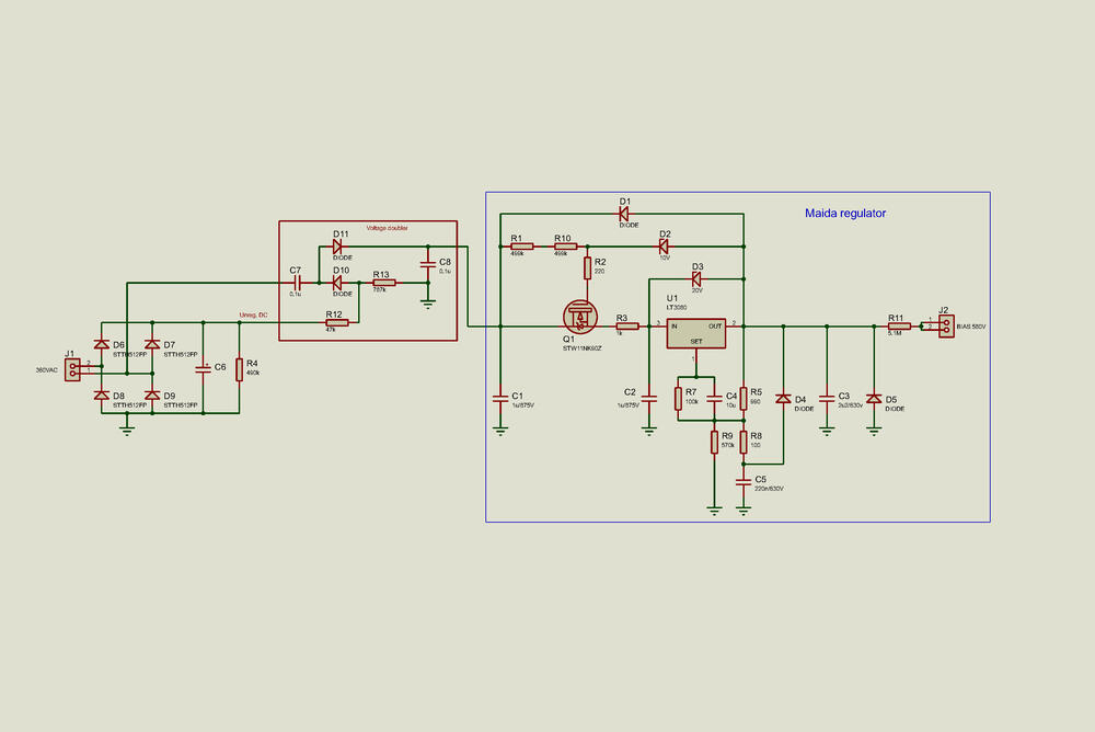
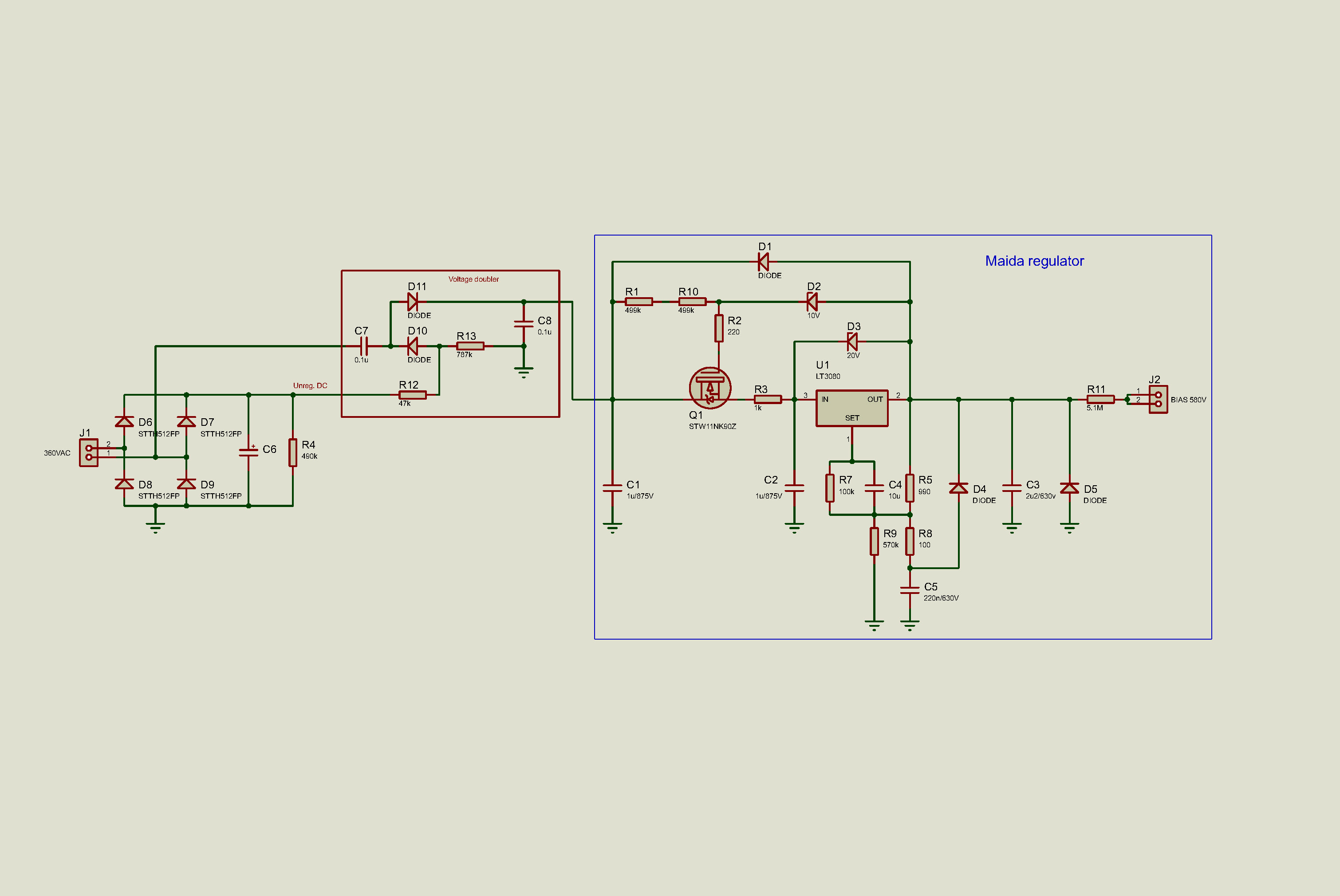
 Yes, you are correct. In the 21st Century Maida design R3 and R9 are power resistors. When used for “BIAS 580V” the need for current is about 1 mA, mostly for the voltage divider R5/R9. Highest heat dissipation would be R9, 0.6 W and I’m thinking of two 0.1% thin film resistors here. As for capacitors the C5 (220nF/630V) also needs to be a through hole.Draft of BIAS 580V regulator. Works in LTspice. After the voltage doubler is a Maida regulator. Q1 is a to247 mosfet, C1-3 are 27.5 mm film caps and rest of parts are surface mounted. For Maida regulator see: https://www.ti.com/lit/an/snoa648/snoa648.pdf?ts=1600430373786&ref_url=https%3A%2F%2Fwww.google.com%2F https://www.diyaudio.com/forums/vendor-s-bazaar/209067-21st-century-maida-regulator.html https://neurochrome.com/collections/power-supplies/products/21st-century-maida-http://www.pmillett.com/HV_reg.html
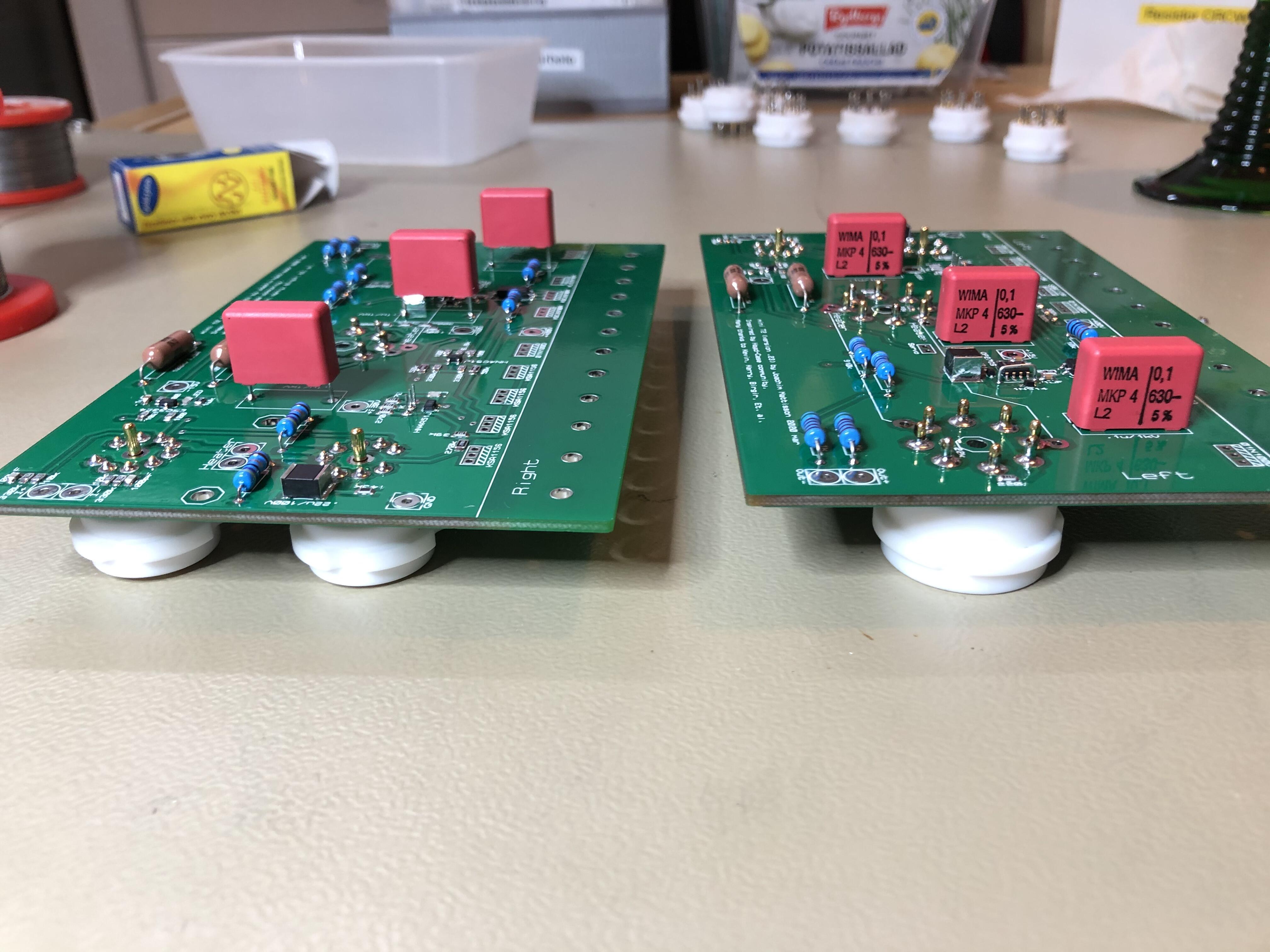
 For BOM mini T2 v.22_Date_2020-02-16.xlsx try this: link Please tell if it works. I don't really know what I'm doing. September 20 - Above link to BOM removed as attached files can be downloaded from HeadCase again.Check this miniT2 BOM - BOM mini T2 v.22_Date_2020-02-16.xlsx Well, seems it doesn't work....My experience is that the balance servo is very efficient so 50 mV is expected. As for offset – 5K trimmer parallel with 510R resistor reduces highest emitter resistance to roughly 465 ohm which probably is too low. May I suggest replacing R73 (6.2K) with a 10K trimmer and keep R64 (510R) untouched? I have used that for a long time and it works great.Me too think FedEx is nice. If I put a Mouser order at 18:00 Swedish time I usually get a knock on my door at 12:00 second day after – 42 hours from Texas to remote Sweden. 🙂Took some time but eventually I got a CD sent to me. Thanks for post!Now completed mini T2 with the new boards version .23. Squeezed in film caps with 0.8 mm leads on right channel with 0.76 mm hole diameter, elevated and soldered both sides (see below). Both channels worked right away. Only issues I’ve found with those new boards are mentioned in posts above.
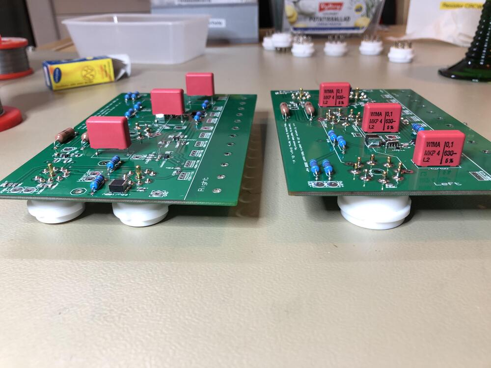 Warning! 0.1u/1kV film cap pads on right channel have 80-30 pads meaning hole diameter is 0.030 in or 0.76 mm. This is to tight for most film caps that have lead diameter of 0.8mm. There are some Panasonic, Cornell Dubilier, Nichicon and Vishay caps with 0.6 mm leads and 15 mms lead spacing. Do not drill the holes for the film caps. The through hole plating is needed as it ties ground planes together and also needed for -460V to be fed to none tube side of the board. Left board have 90-40 pads – 40th or 1.0 mm. This mistake is done by me and the blame is entirely on me. I’m sorry.






Important Information
By using this site, you agree to our Terms of Use.