


Pars
High Rollers
-
Joined
-
Last visited
Everything posted by Pars
-
Happy Birthday Jeff! Sent from my iPhone using Tapatalk
-
I’d check, but those you should be able to do the drive and memory yourself. Judging from my 2012, they aren’t too bad to work on. So get what you want for processor but limit the rest. I’d take a look at iFixit for instructions, and look at OWC for pci SSDs. Not sure if Samsung is offering those yet or not. Crucial, etc. for RAM. Sent from my iPhone using Tapatalk
-
At home, supposed to have 150Mbps
-
For the CFP you need one board per channel, so 2 for a stereo SE, 4 for balanced.
-
This is the link to board files: https://drive.google.com/drive/folders/0B_iJFfZStuVhSE5nOHBVdTByR1k This is the CFP2 (single ended) and CFP3 t(balanced) thread (Kevin or someone correct if this is wrong): There should be a BOM posted in the thread, though with the recent update for current mirrors in the feedback loop, it probably needs some adjustment. If you can't find one, I know I have one here somewhere.
-
Hmm, must have forgotten to post the follow-on. The 402R resistors got me pretty much where I wanted to be (262mV, or 13mA). Temps didn't seem to go up much when running it for half an hour or so. On the first bank, I tried a THAT chip instead of the FETs and no effect on bias. Used hot air to remove the 2 over by the Meanwell and got them done without hitting that. Used an iron for the soldering. So now I need to order more 402R as well.
-
I would think so. That is in the upper half at least of the range for B devices.
-
Noted. If going to the 402Rs doesn't get me where I want to be, I may replace the LEDs with the Bivars that RudeWolf had in his BOM (1.9V). I had also forgotten to order the 0R resistors for the servos, so will solder on resistor leads until I get some. I was disturbed to see how many items in my spreadsheet I forgot to order, even though I had built a separate tab which was a copy for importing into Mouser for the order. I went thru the order and removed backordered items, so that may be why (I forgot to find alternate source). Oh well
-
^ Here is the original post on that. Measuring mine, I'm seeing 1.64V across the LEDs (LTST-C170CKT). I believe 1.7V is the design spec? 1.06V across the 422Rs Vbe for each of the transistors by the LEDs seems low at 0.53V. I let it run 45 minutes or longer. Bias voltage across 20Rs was up to 220mV, so 11mA. I think I will start by replacing the 422Rs with 402Rs. I don't really want to increase the bias resistors above 255R, but trying to balance sound with heat. This is in open air, and it is winter in Chicago, and in the basement. I was seeing device temps around 60C, a bit higher in spots (IR measured). I do have my full size amp downstairs to compare to as well.
-
Same serial number and all? Agreed, wanker tech...
-
I think Kerry’s original post was in the group buy thread (possibly deleted now?). At any rate I quoted it in this post. Sent from my iPhone using Tapatalk
-
The input transistors shouldn’t effect the bias current. My full size is also using JFETs (Toshiba). I thought the 422R had to do with the LEDs having a higher Vf than the original 1.7V used in the full size versions... Sent from my iPhone using Tapatalk
-
I was going to suggest the Gilmore CFP2. If going balanced I would front it with a ubal-bal board for flexibility in input choices. Cheap, easy to build, and very good compared to the other suggestions. Use the golden reference PSU and you’ll be, well, golden. Sent from my iPhone using Tapatalk
-
Well the issue is the low bias current. 170mV is only 8.5mA. Target was 15mA. The bias resistors are 255R. I’m running 261R on my full size and getting north of 17mA on that (same PSU voltage). After seeing the posts on here of people having to dial these back with 240R, 220R, etc. I was expecting higher. I’ll look at it some more. And those are Linear LSK489/LSJ689 on some adapters I did. Sent from my iPhone using Tapatalk
-
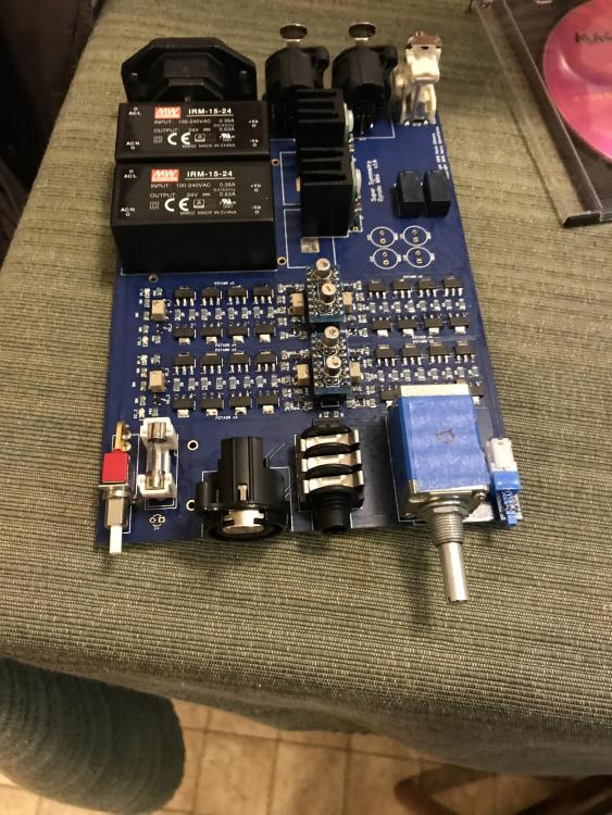
Got the first of the 3 minis finished more or less (less case, etc.). Had it running on AC for about 5 mins or so. 255R bias resistors, +/-20V PSU... I'm only seeing around 170mV across the 20R resistors. Low, and seems strange with others getting 18mA with 220R, etc. As for adjustment (offset), I used the pots by the LEDs to get the offset between +/- for that channel centered around ground, then had dialed the individual offsets in using the other 2 pots. Anyone have a different adjustment method? I may play with the pot by the LEDs and see if that does anything to the bias current or not.
-
I suppose chassis ground would be to code, though from what I have seen no one who had built/cased one did that. Were you going to put holes in the bottom panel for feet? You could use the one closest to the IEC to run a ground wire. Make sure there isn't any interference from anything on the amp board. The RCAs (and the Neutriks) can be tapped. I just tapped an RCA for M3, and would think 4-40 would work as well. I prefer your v1 lettering above as well. EDIT: for grounding, the IEC has 2 mounting holes in the rear panel, which appear they require a screw/nut. As long as the screw contacts bare metal, those would work for the case grounding as well.
-
Sent from my iPhone using Tapatalk
-
Why do bodily parts start puckering up every time I hear the word “bursun”? Almost as bad as when I hear “bybee ” Sent from my iPhone using Tapatalk
-
^ Posted the gerbers in the GB thread, but here they are again as well... Bridge_Vert.zip
-
Some Gerbers... Schottky diode bridge board, vertical diode mtng: Potentiometer: TKD 4CP601 Only TKD 4CP601 / 4CP2500 TKD 4CP601 / 4CP2500 / Alps RK27 Quad GRLV 35mm SiC diodes https://www.head-case.org/forums/applications/core/interface/file/attachment.php?id=21170 Latest CFP2 https://www.head-case.org/forums/applications/core/interface/file/attachment.php?id=20304 Note for those wanting to do one of those balanced: you might want a uBal board to front end that. Bridge_Vert.zip TKD 4CP601 only final.zip TKD 4CP 2 pot final.zip TKD 4CP 3 pot final.zip EDIT: If you have either of the CP2500 boards run, make sure they thru-plate the slots.
-
I could be interested in going as well. 4 hour wait for a burger? Heh. Sent from my iPhone using Tapatalk
-
If they are DC servos, then no, they will not change the sound signature if the servo is implemented correctly. But as long as the opamps you are trying can handle the voltage requirements, who knows? The opamp in question is probably implemented with dual supplies. Most opamps seem to be rated for +/- 18V. The OP27 is higher (don’t recall what exactly) and the OPA445 higher yet (quite a bit). If the offset is low and stable, you could try it without the opamp(s) in place. I don’t have a copy of the Krell schematic though, so can’t say for sure. Sent from my iPhone using Tapatalk
-
I’d match for hFE, but also try to get Vf (also known as Vbe) as close as possible as well. I’d shoot for 5% if possible. Matching the N and P is often nigh impossible depending on device type. You just have to do the best you can. Sent from my iPhone using Tapatalk
-
Why would you want to do this? What do you hope to achieve with your “upgrade”? What voltages are you running your PSU at? Sent from my iPhone using Tapatalk
-
Yep. It is what it is. Nevermind...


