Pars
-
Posts
8,601 -
Joined
-
Last visited
-
Days Won
7
Content Type
Profiles
Forums
Events
Everything posted by Pars
-
RIP Roger!
-
Many people feel that R2R sound more "analog" than sigma delta DACs do.
-

and now for something completely different part 3
Pars replied to kevin gilmore's topic in Do It Yourself
These are really more matched as pairs, though having them all match if possible is always good. I did Q14/Q16, Q12/Q13 and Q5/Q17. Q21 is by itself, so no matching. For the front end, Q1/Q2/Q4/Q6, Q9/Q11, Q3/Q8, Q15/Q19, Q10/Q7 and Q27/Q28 if you can (SMT, but I was able to do some matching while still packaged by pushing resistor leads thru the covering. -
and now for something completely different part 3
Pars replied to kevin gilmore's topic in Do It Yourself
Because these are used in a Darlington configuration, the matching is a bit different on these. You can use either the MJE or MJF (the MJE tabs aren't isolated so you'll need pads and washers to insulate these from the heatsink). I would probably suggest 16 of each or so? -
Happy Birthday Craig!
-
Stay safe NE'ers!
-
Steve, Here are the gerbers for the SOT23 Linear duals and for the original Toshiba 2SJ109/2SK389 duals. Note that this board is not compatible with the BJT 7 pin package (2SA1349/2SC3382 IIRC). THAT340- SOT23.zip THAT340-J109-K389-JFET.zip
-
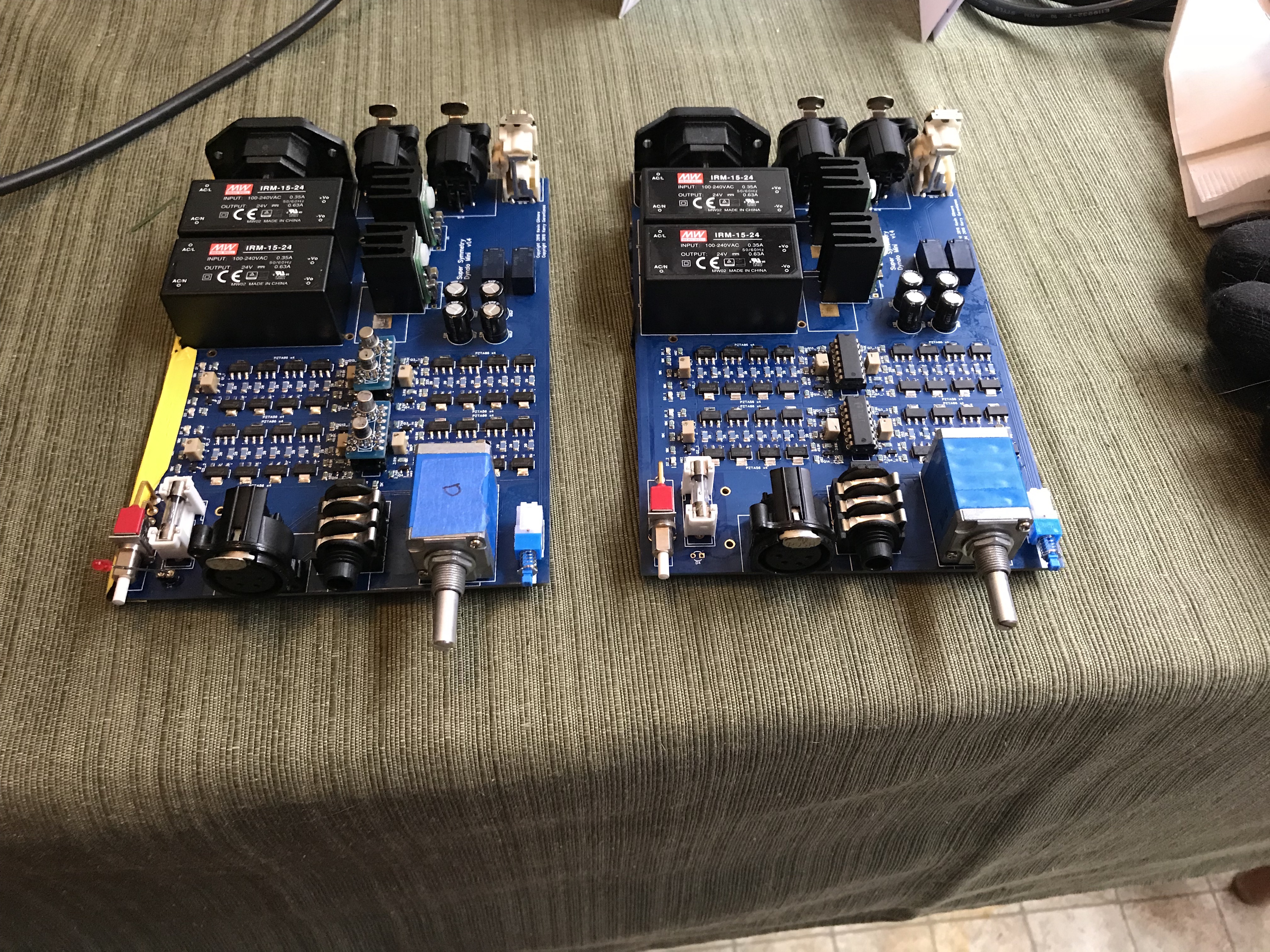
Interesting problem, at least to me, and might help someone in the future with these. Fired up the 3rd board yesterday, and all looked well (LEDs, etc.). However, there were problems: Problem 1: Went to check DC offset, and the R channel (both +/-) was showing 4V offset. Not good. After looking the board over, I suspected one of the small transistors (MMBTA06/56), as there were a couple that were a bit crooked and I couldn't tell if all pins were soldered or not. Q3_2 looked suspect, so removed with hot air, which also took the 3.01K resistor right by it. Cleaned and fluxed the pads and got it put back together. I also touched up the solder connections on the others on both channels in this section of the board. Fired it back up, same problem. I then looked at Q1_2 and Q2_2. Straightened these and touched up the solder joints. Success! But I wasn't quite done... Problem 2: Adjusted DC offset (no pot in yet, so will recheck once that is in). I then started going down the 20ohm resistors checking the biasing. All looked good until I got to the L+ channel. These alternated from 290/220mV (they should be balanced between the NPN and PNP sides). The 20 ohm for the closest to the center NPN showed no drop across it. I retouched the solder joints for this transistor, but same problem. Removed and replaced the transistor. Success. Now bias was the same as the other channels and consistent across all resistors. Ohming that transistor out, it appears to be good. I couldn't see any evidence of solder on the bottom of the tab (collector). I know when I checked voltage on it, it showed V+, but I was probably pushing it down with the probe. The collectors aren't connected on the middle small pin on these from what I can tell in the gerbers. I had used hot air to install these originally, but had hit the tabs with an iron with a wider chisel tip. These are considerably more difficult to troubleshoot/rework than the full size dynalos are, so it pays to take your time building them. Before I checked the end transistors in #1, I wasn't relishing having to do more extensive troubleshooting/rework on this. The other two boards came right up with no problems. And I'm still not fond of SMT pots Also, since I don't think this is documented anywhere, with the board facing you (pot, outputs, etc.), looking at the channels as quadrants, they are laid out as follows: L- L+ R- R+
-
Any idea when you will close this GB? The amp boards are feeling naked... I know you wanted to wait for the board GB to end and sync with that, but by the looks of it, that one might be open for awhile...
-
^ Starting to get interested in these myself. I know you were getting some of the buffers for something Michael, but had you thought about using a ubal board for the balanced on the DAM1021 instead of the opamps Soekeris is using? Also, did you have any luck finding a Mac serial cable (USB->serial)? I thought it was for dealing with the DAM1021?
-
Happy Birthday Naaman!
-
Not the original one at least (2SA1968s for starters). I did see a thread for a BJT build of this, but didn't go thru it. One of the stat guys can advise you much better than I can though...
-
An oldie but longtime fav...
-
^ Link in the 1st post to place your order...
-
^ There is a link in the first post to the google sheet to place your order...
-
Congrats bui501! And Blueman2 for getting yours running (and keeping it that way).
-
After working with the mini boards in 3oz copper, I would strongly suggest going 1oz... Little parts and the heat to do heavy copper isn't a good combo. But I won't be buying any, so go with what the majority wants.
-
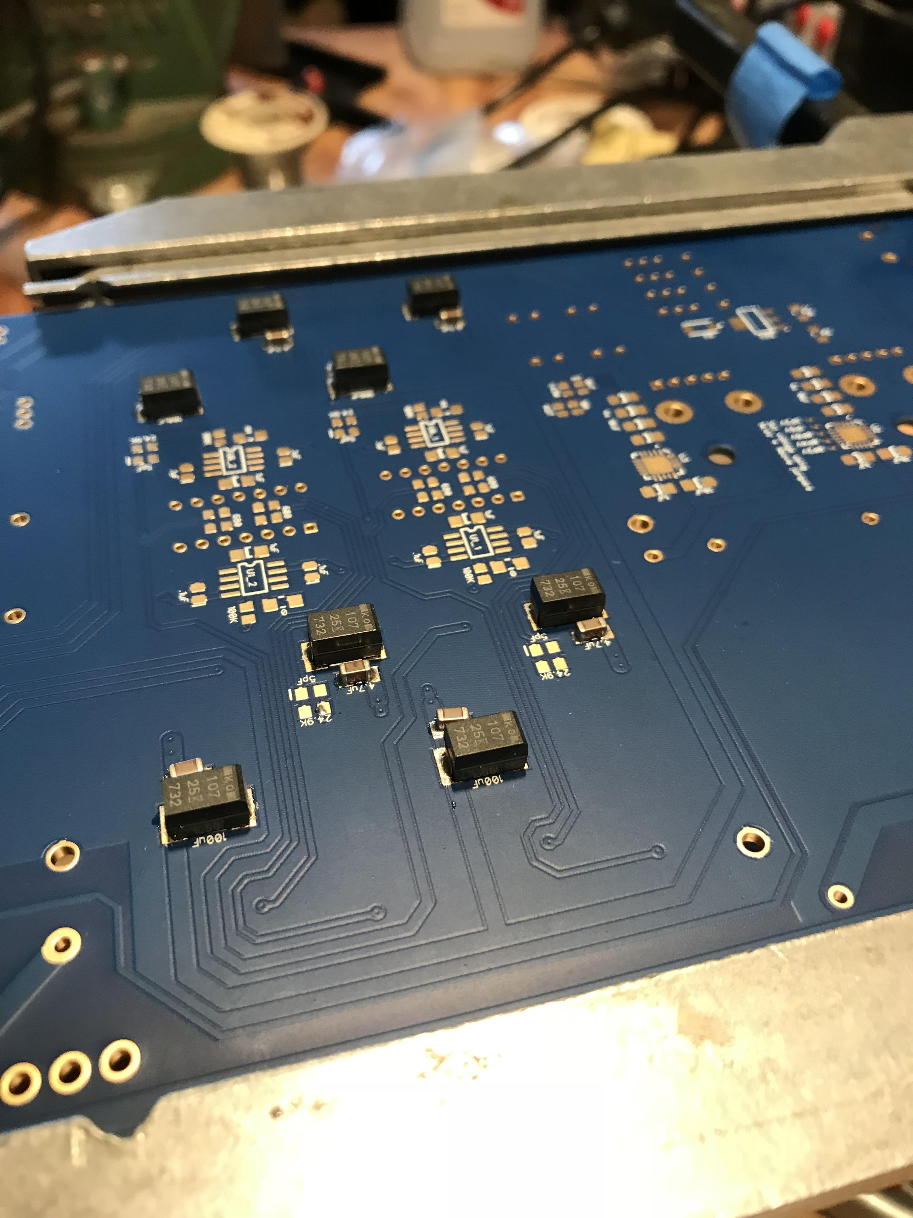
Moved a couple of 4.7u on the above to straighten them. Two down (less casing), 3rd (above) in progress.

-
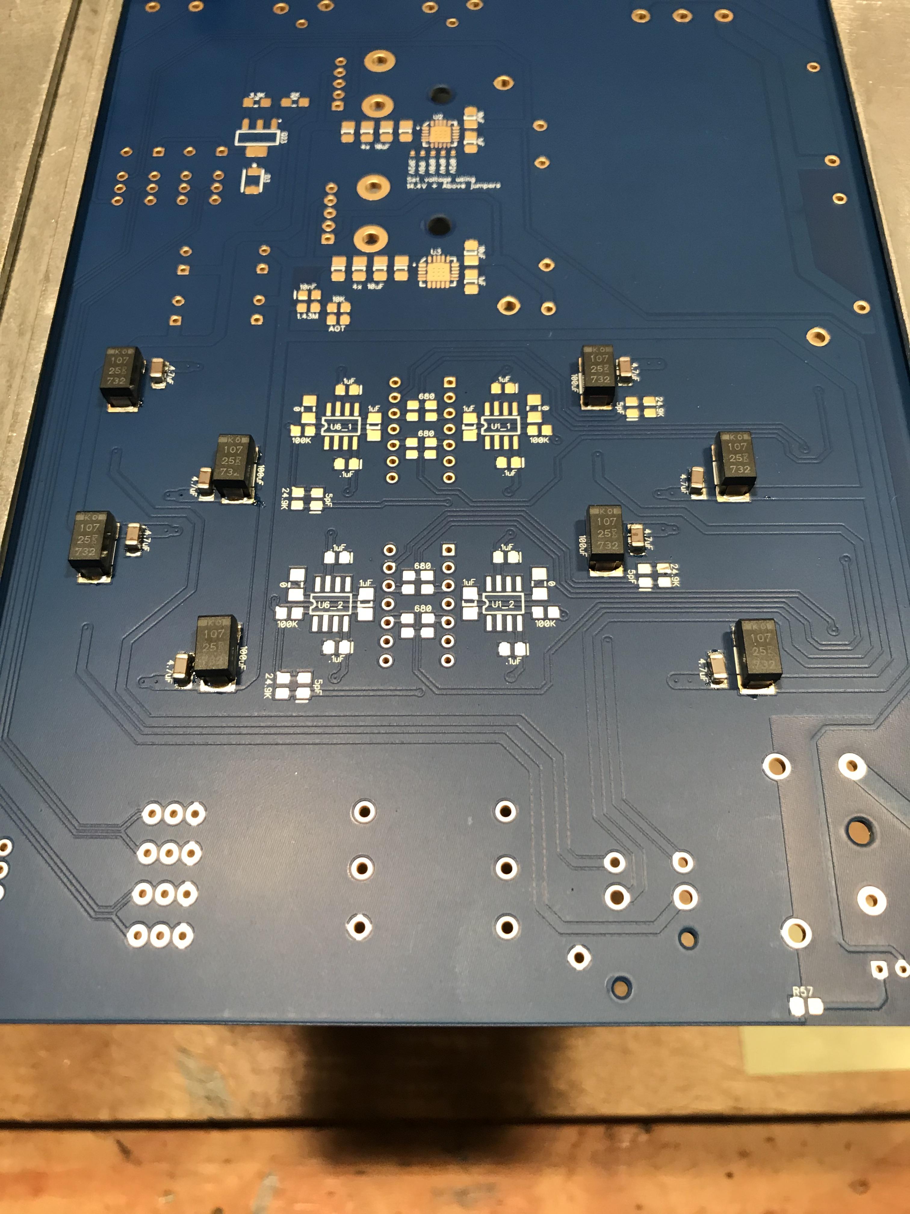
Did a little "baking" yesterday, using the Kester EP256 paste I got. Still had to preheat the boards with a hot-air gun before applying the paste, but I like this paste a lot better than the Chip Kwik I had gotten. I think it turned out pretty well.
-
Happy Birthday Al!
-
Mini Dynalo After running the amp for over an hour, bias was 14+mA, so right where I want it to be. I thought it might be interesting to create a table or spreadsheet showing different users biasing and results, so I made a Google sheet, here: https://docs.google.com/spreadsheets/d/1D5LDuRdupZRoWR-GfAd03fkFSBAMY4-E_VcYfCAI1Z0/edit?usp=sharing Go ahead and fill in your info if you like so this is available for all to see. Note: this is the first time I've created a Google sheet, so let me know if you can't edit it and I'll try to figure it out Heatsinks: I've been looking for some. The ones that @mypasswordis mentioned from ebay don't seem to be available any more, and I'm having a hard time finding any that appear to be suitable size. There are some I almost pulled the trigger on that were 50mm x 25mm, but the 25mm would leave the end transistors half covered. I could get the Fischer SK81/37.5/SA from TME and cut them in half, but I'm trying to avoid that if possible. I'd need enough for 3 amps. EDIT: Found these, 45 x 35 x 18mm on ebay https://www.ebay.com/itm/263051780518?var=562054192200
-
Very sorry Todd, RIP Carol!
-
I have some of those as well, from THL audio IIRC. I don't recall any issues with them, other than the ground being a bit of a pain in the ass to solder. I'll check mine, but I've had them a few years now. They do seem to be made pretty well; not as nice as the Cardas rhodium, but a lot more reasonably priced.