Laowei
Returning Member
-
Joined
-
Last visited
Everything posted by Laowei
-
Replacing the USB is pretty straight forward. Only removing/assembling the Yggy case with its plethora of screws can take some time. Gotta send in your Yggy for the Analog 2 upgrade. It’s more than just the replacing output PCBs. They also update the DSP firmware to deglitch the original Megaburrito digital filter, and add/replace/rework parts to upgrade to the current production configuration. They have learned some things to make it sound better in the 3+ years it’s been out. Sent mine in yesterday. We’ll see how it turns out.
-
Yeah, they mounted the DAC chips on the analog board. The Analog Devices AD5791 run $85 each in quantities, and the Yggy takes 4 for the 2 channels. Don’t know if they recycle them for the new boards. Or what that will do for product reliability if they do. Can’t see them just tossing all that expensive silicon in the garbage.
-
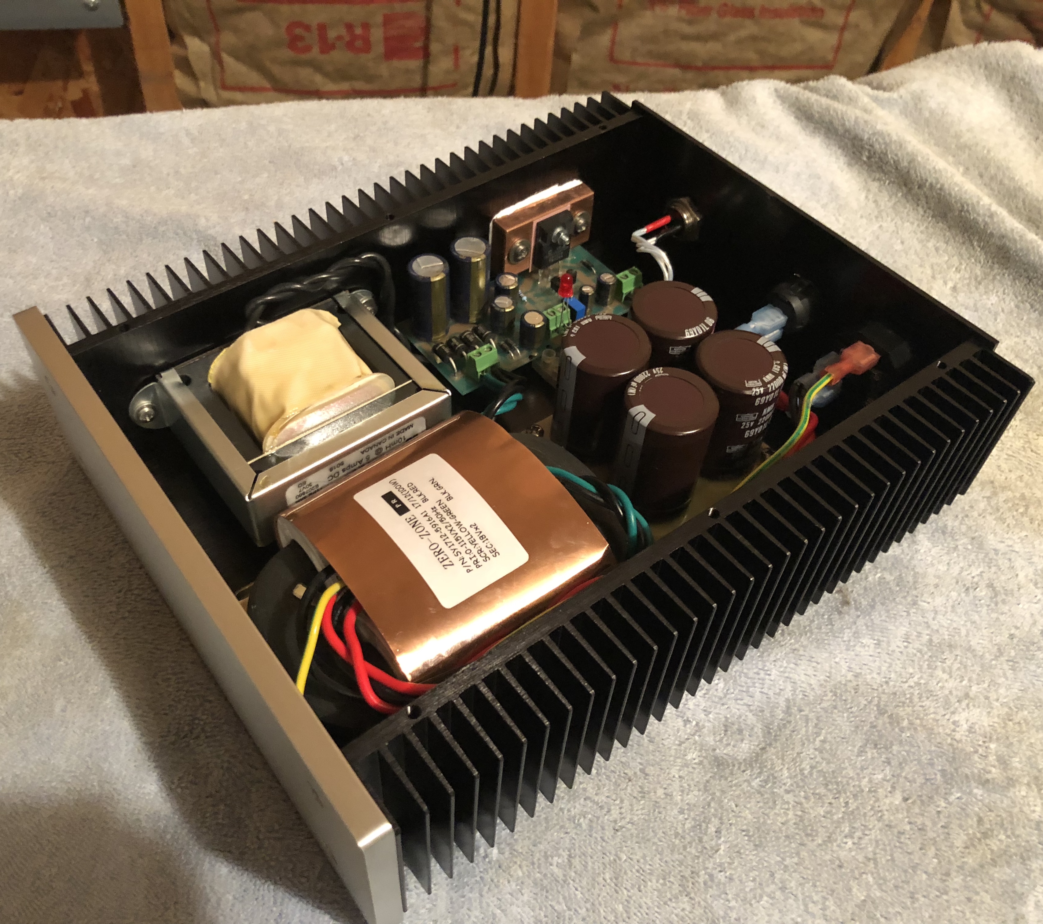
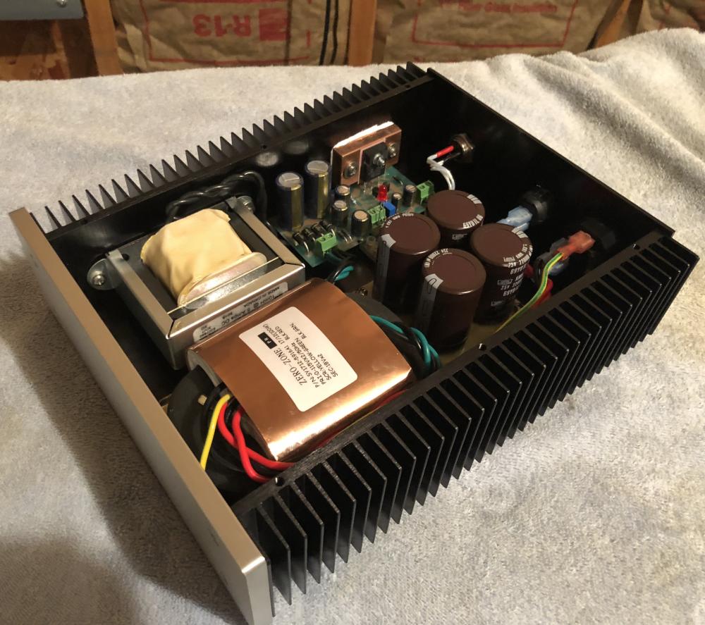
Mostly a packaging job. Had around an old Paul Hynes PR-3HD 18.5VDC voltage regulator and 2x 18VAC Rcore transformer I bought years ago to use in powering an old Mac mini. It’s capacitor input. Wanted remake as a 12VDC supply and was able to adjust it to design. Bought a bare case off eBay. Added a inductor and capacitor bank to use as choke input expecting ~35% rectified DC voltage drop. Powers up no-load OK. Need to now get some power resistors to stress test at 5A to see if drop out is exceeded and starves the regulator. Might have to go to a 2x 22VAC.
-
I like my SR-207 I kept as backup.
-
https://m.ebay.com/itm/HPS-2-Official-STAX-natural-wood-headphone-stand-NEW-From-Japan/122835413608?epid=0&hash=item1c998faa68:g:oxEAAOSw3PBZzG7D
-
-
MOAR MARBLE!!!
-
Don’t forget separate 2X 18VAC secondary taps for supplying power to the input section. 200mA would be overkill for the GG.
-
Interested too.
-
-
+1
-
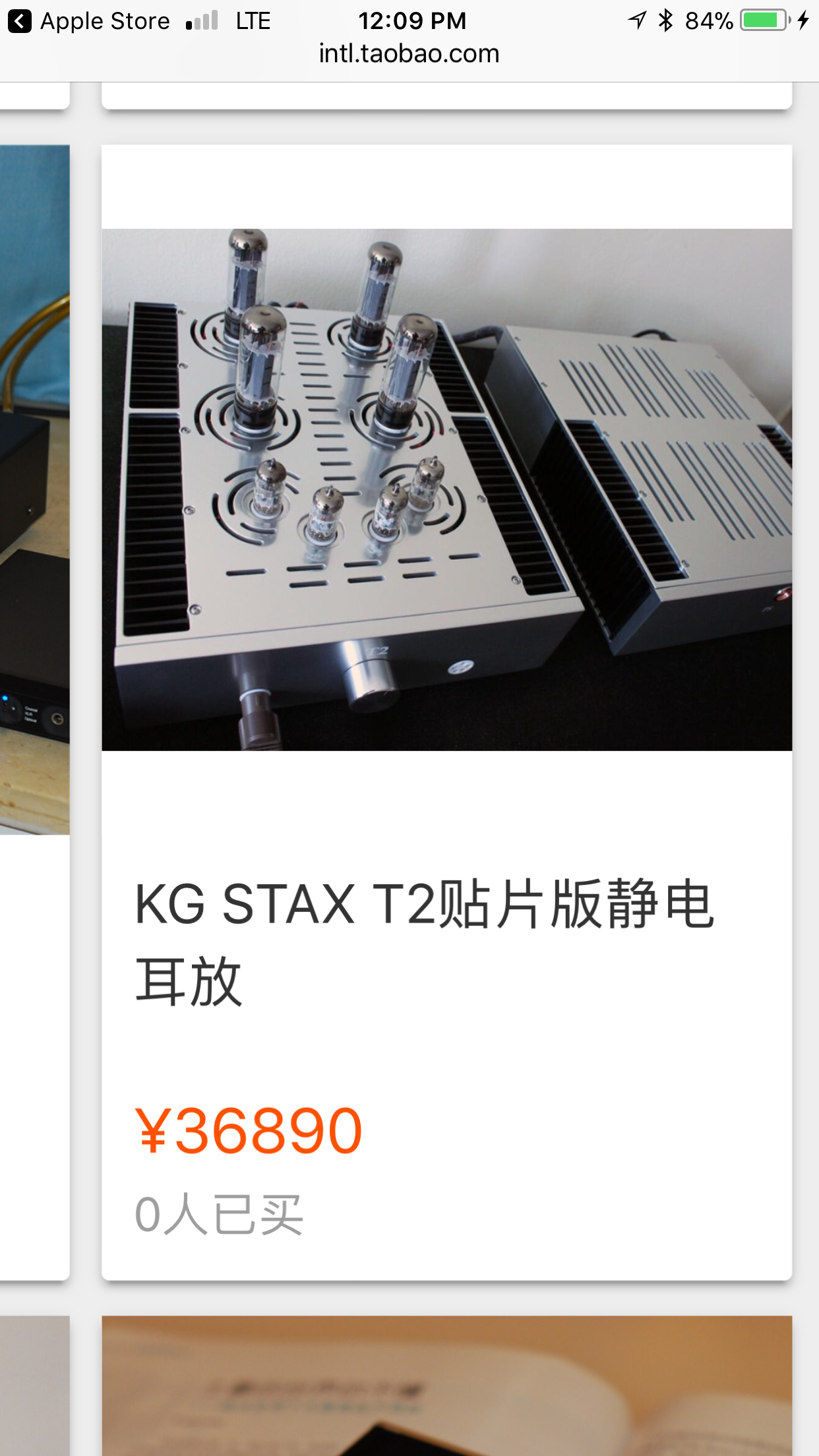
The fake goes deep on Taobao.
-
Shit, there’s even a faked Kerry built T2!

-
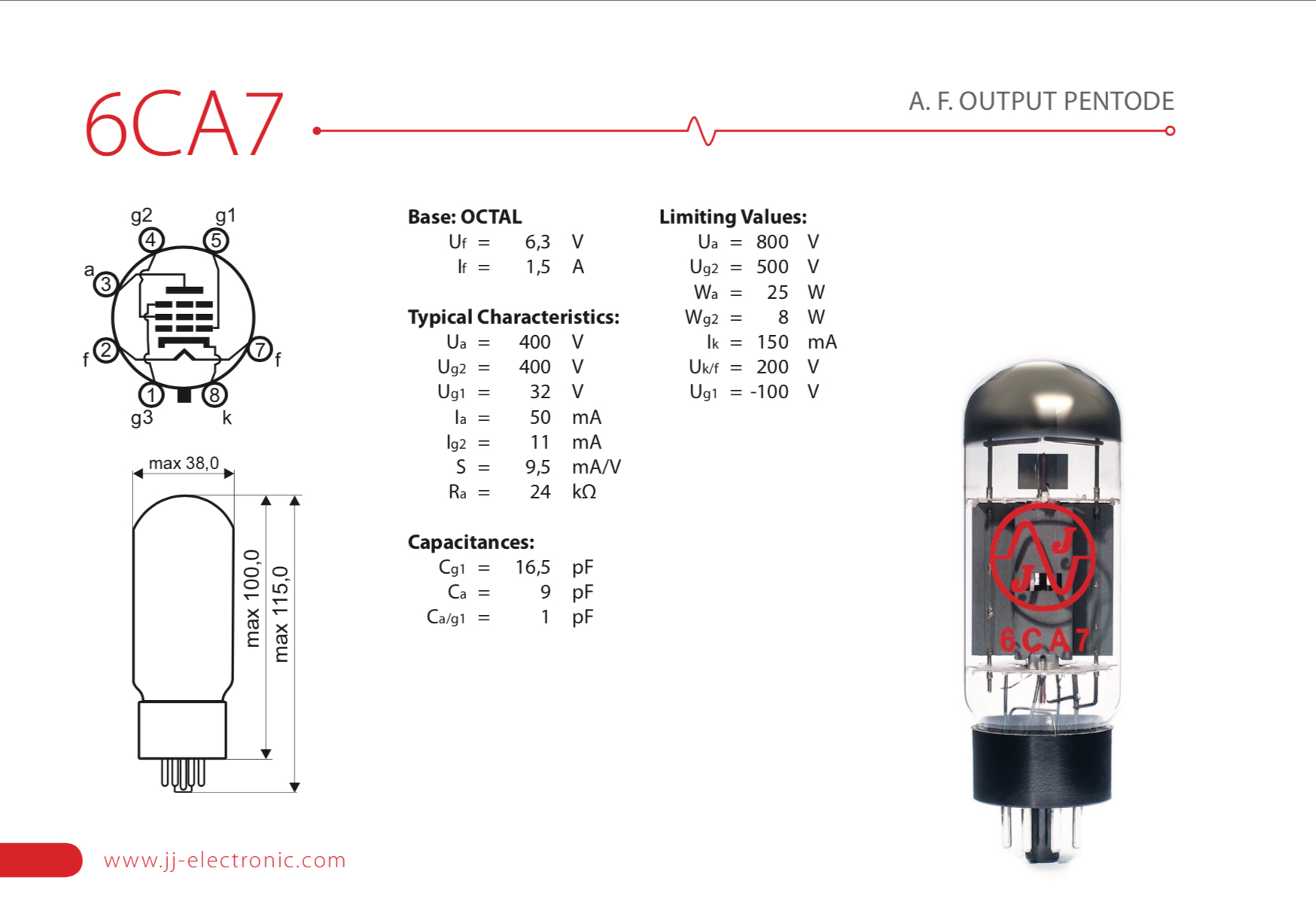
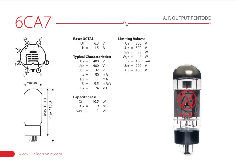
More tube weirdness. The JJ 6CA7 is a Beam Pentode, with the beam forming plates connected to pin 1, similar electrically to the pentode EL34’s G3. The other big bottle 6CA7s are Beam Tetrodes, with the beam forming plates internally wired to the cathode (pin 8). Pin 1 is NC in this case. In the GG, G3 is tied to the cathode on the PCB. So no difference electrically between using any EL34 or 6CA7 in that position. In the T2 circuit, G3 is tied to the plate and draws current, so may have stressed the JJ 6CA7 beyond what it could handle. The internally connected EH 6CA7 doesn’t see that.
-
Indeed, congrats on the fantastic build Whitigir! You’ve really been on the STAX DIY fast lane this year. Enjoyed following your journey.
-
On a hopeful note, maybe the measured values are accurate with matched sections and are useable.
-
Similar text bleed and errors on both. The silkscreens look like they were made from a second or third generation photocopy. My guess is they are relabeled and fake.
-
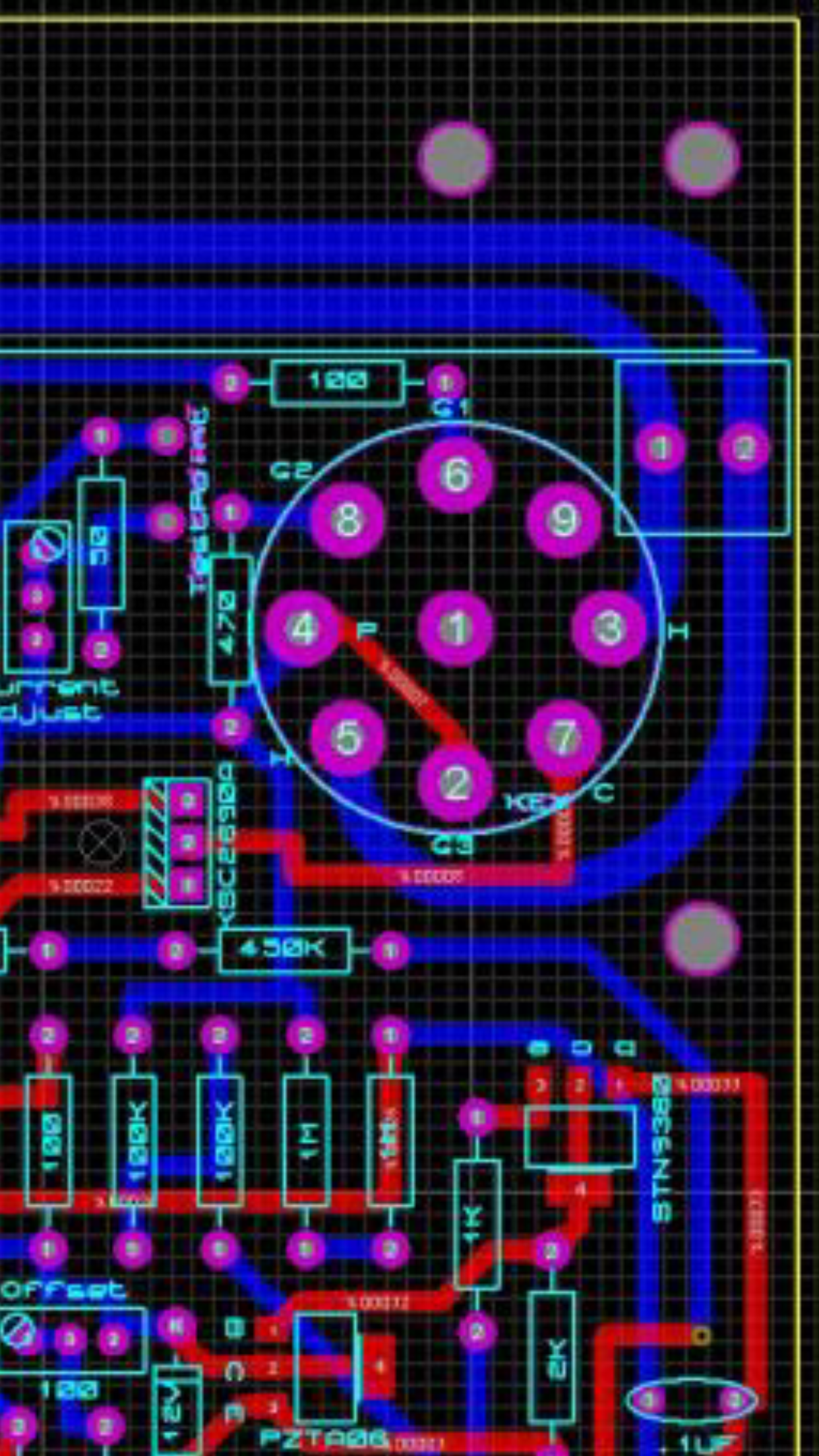
The graphic is from earlier in this thread where the PCB was first posted. It matches the traces on my PCB. Both appear similar and no printed Revision level is found. I bought my boards from another member, so probably the first. Kevin quickly drew up the GG (a tube version of the Carbon) to humor us vacuum tube Luddites. Your example looks like a later version. Basically the same, just tidied up a bit. The amazing thing is, even the quickie electrostatic amp designs that Kevin publishes, are simply incredible sounding. He is an irreplaceable source of inspiration for us DIYers.
-
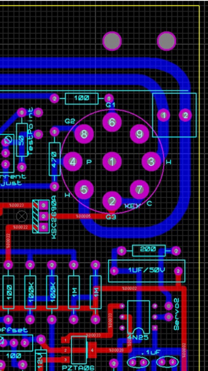
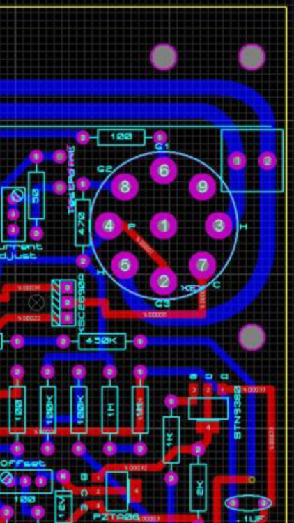
Another couple of questions on grid connections in the output sections’ triode wired EL34s in the GG. 1) Per the GG PCB, and also the KGBH schematic, G3 (the suppressor grid) is tied directly to the cathode.This is the conventional connection for a grounded cathode circuit. In a grounded grid circuit where the cathode is driven, wouldn’t the added G3 parasitic load be harder/non-linear to drive? 2) In the DIY T2 and T8000 Sandwich PCBs, G3 is directly connected to the Plate. circuit. Is the suppressor function really needed in a grounded grid triode? Seems like driving the cathode only would be optimum in a grounded grid circuit. 3) Does the STAX T2, or DIY T2 have a history of being harder on the output EL34s’ G3, than a KGBH? I searched and could not find any mention of this. 4) Any advantage to cutting and modifying the traces on my GG PCB to try out the G3 to Plate connection? Thanks for any advise offered. T8000 Sandwich: GG:
-
Not in my experience. I hear a clear improvement between the Gen 5 and Gen 3 in my Yggy. Lots of others have reported the same.. The Eitr I first bought to try out crapped out on me, and I returned it. Their QC sucks. Have you contacted Schiit and complained? You may have gotten a sour unit too.
-
How does the Gen 5 compare to the previous USB input?
-
The Gen 5 USB does a lot better job than the stock Yggy Gen 3. For $100, I think you will be suprised and happy with the SQ after swapping them out. Do you have a lot of DSD content stored? Have you tried converting to hi-res PCM on the fly from your computer?
-
Much of a problem getting the LEDs on the main PCB lined up with the front holes on cover?
-
Thanks Kevin. Your generosity in taking the time to dissect and explain this is greatly appreciated.
-