justin
Manufacturer/MoT
-
Joined
-
Last visited
Everything posted by justin
-
Happy Birthday!
-
Just a suggestion I haven't tried this but I would also try disconnecting the output buffer and take the feedback from what would have previously been the input to the buffer - then re-run all of these trials. very curious if the results are different
-
600 or 680 can be used. 680 will be slightly higher front end gain 300 is correct 4.2k is just higher gain than 1.9k I don't remember what the 50k and 25k are -- SS feedback resistors? if so also just higher vs lower gain If only using SS, it's possible you can eliminate the 4.2k, as long as there is still another resistor in parallel with it. what you would do is measure the gain with and without the SS feedback resistors, and choose values so you have ~6dB less gain with the SS feedback resistors installed
-
you may be hearing residual DC offset from the amp boards at the time the relay engages, as it can take a short time for the servo to null this voltage completely - possibly longer than the delay on your power on relay. things you can try: - use ground as the input signals to the protection board, do you still get turn on noise? - measure the DC offset at the time the relay engages - significantly increase the delay of the relay - measure the min. +/- DC voltages that cause the protection circuit to engage, for each channel - lower the threshold of protection
-
I cant even tell if this is a stupid question but where are your heatsinks? if you try to power it even for a short time without heatsinks the bias is going to be very unstable 3.6V sounds right to me, 5V would probably result in about 700mA bias
-
Frank Ricard still did a better routine
-
The output ripple voltage of a DC/DC converter is often specified at a 20 MHz frequency to provide a more comprehensive view of the high-frequency noise performance. Here's why: 1. **Switching Noise and Harmonics**: While the switching frequency of the converter might be relatively low (e.g., hundreds of kHz), the switching process generates high-frequency harmonics. These harmonics can extend well into the MHz range, and measuring at 20 MHz helps capture the impact of these high-frequency components. 2. **Measurement Standardization**: Specifying the ripple at 20 MHz has become a common industry practice. It provides a consistent benchmark for comparing the performance of different converters. It also ensures that any high-frequency noise generated by the converter is accounted for. 3. **Real-World Performance**: In real-world applications, the DC/DC converter might interact with other components that are sensitive to high-frequency noise. Measuring ripple at 20 MHz helps ensure the converter will perform well in a wide range of conditions and with various loads. 4. **Electromagnetic Interference (EMI)**: High-frequency noise can contribute to EMI problems. By specifying the ripple voltage at a higher frequency, manufacturers provide a clearer picture of potential EMI issues, which is crucial for compliance with regulatory standards. Overall, the 20 MHz specification helps designers understand the converter's behavior across a broader spectrum of frequencies, ensuring more reliable and noise-resistant designs.
-
This is all that was provided: I think I would prefer to use our 2.5kg (5lb.) > transformers, as the high voltage secondary needs to have a lot of insulation > to keep capacitances down. > > Spec: > Transformer for SE amplifier, size as LL1620 etc. > > Primary 1.2k impedance, 280V anode voltage, > standing DC current 200 - 300mA (you will need to specify) > Input signal power around 10W > > Secondary 1 (electrostatic speaker) 1600V P-P > (turns ratio 1 : 6). > Does this output need a centertap for offset > voltage or for ground reference? > > Secondary 2 (low sensity headphones) , 15W > into 50 ohms -> approx. 27V rms (turns ratio 3:1 for 1.2k : 50) > > Secondary 3 (6 ohms loudspeaker and sensitive > headphones), 15W into 6 ohms -> approx. 10V rms (turns ratio 14:1 for > 1.2k:6) 3729_SE_connections.pdf
-
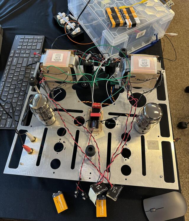
I met Per Lundahl at Capital Audio Fest last year, and in trying to figure out what I could use I'd have for Lundahl transformers I asked about winding something that can drive e-stats, planars, low impedance, speakers from separate taps. I had also just bought a bunch of 6336B dual triodes, so thought that might work. The transformers came and many months went by but finally rigged something up. Basically right now it's just 6336B with both triodes in parallel, running about 200mA with a B+ of 260V. There's an e-stat output that steps up, and also 50 ohm and 6 ohm outputs. The grid voltage is set by a bunch of 9V in series. The black box in the middle on top of the Wendy's napkin is a little 4W 12V to 600V DC/DC converter for the e-stat HP bias. I'm actually driving it from the headphone jack of a Ray Samuels Raptor right now 🤣 Have sound coming out but no chance yet to do much further testing
-
here is actual footage from Bing
-
tbh I wrote the post BEFORE I noticed subliminal?
-
Are those Monster cables?
-
-
thank you for your service
-
have to look, probably either a OPA2134 or 2132 But I also tried it without the servo and using a pot instead
-
I was thinking maybe Roonba or the poon as a Neil Young/Schitt homage
-
I've thought about making a pocketable, portable amp for Roon, does anyone have any ideas for a name?
-
if you still have the Brooklyn Bridge you can use it with a Roon core..if a device isn't Roon certified, you can still use it if it supports AirPlay, Chromecast, or USB (by plugging it into a computer or a WiFi/LAN to USB adapter aka 'Roon end point'). Computers don't need to be Roon certified and this includes this like NUCs get on Roon now!
-
Apparently the PCBs were revised to correct the errors and even add the protection circuit - but nobody remembered
-
I did try batteries for just about everything
-
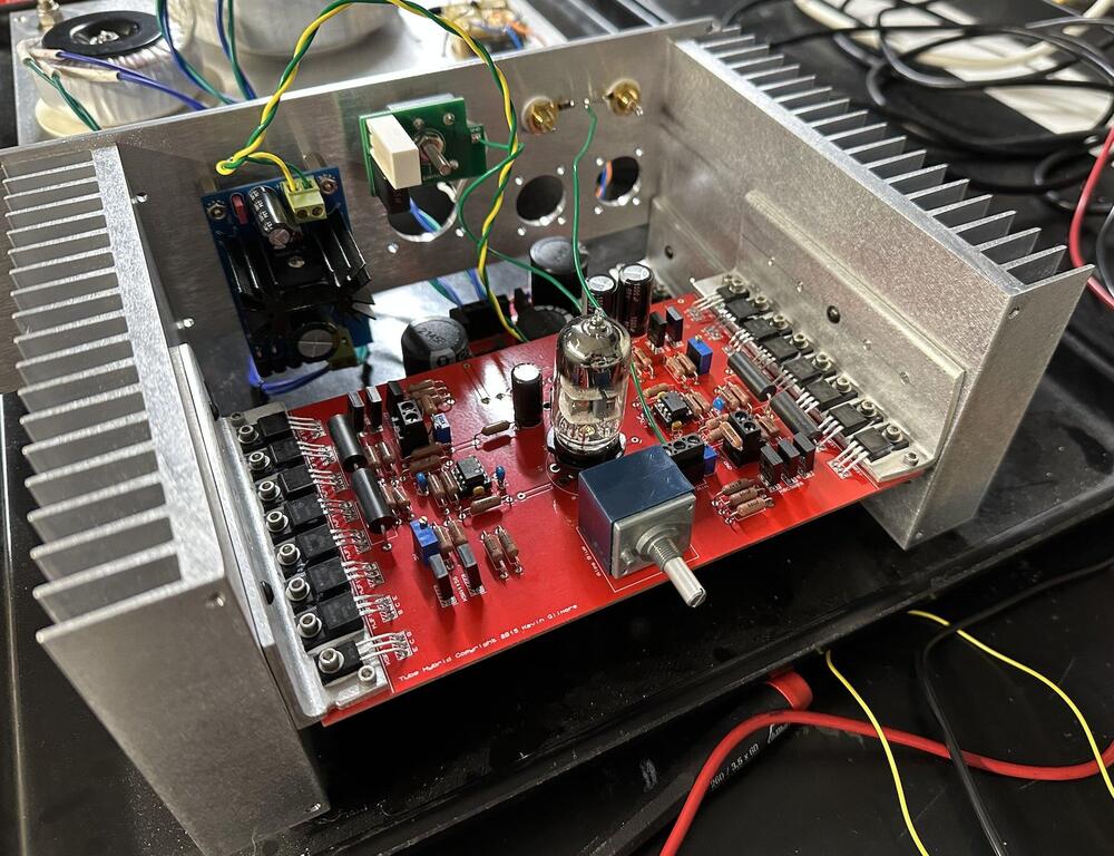
Last year I ordered a lot of different boards of KG's amps/PSUs and had someone here put them together as a project. One of them was this 6DJ8 hybrid that uses the triple output buffer of the CFA3. Single-ended output only. There was 1 missing trace on the board that prevented it from working, found and fixed that, so possibly nobody had assembled one of these before. Problem is there's a substantial hiss (very easily audible with even sensitive planars, something like 0.3mV rms of 'white noise'. The +100V is coming from a TL783 regulator, tried AC, DC, batteries for heater, different grounding, gate stopper resistors, feedback caps, w/out servo..exhausted a lot of stuff but couldn't get more than a few % improvement on the noise. Anyone have ideas? th.PDF
-
I only saw ~2 min of the video but I assume it had something to do with measurements, my favorite part though is people wanting expensive, exotic gear that sounds different, but then acting surprised when it measures objectively worse than a Hospital DAC
-
happy birthday!
-
Happy Birthday! don't work too hard!
-
Birgir "It's not complete trash" for those not familiar this is high praise