

Leaderboard
-
naamanf
High Rollers33Points6660Posts -
Voltron
High Rollers28Points34512Posts -
shellylh
High Rollers25Points18862Posts -
Absorbine_Sr
High Rollers22Points8096Posts


Popular Content
Showing content with the highest reputation on 01/01/16 in all areas
-
8 points
-
7 pointsFilet's with pan broiled shrimp and baked potato. Sous vide rendered a perfect medium rare, seared off after the water bath in a cast iron pan. Not seen is a mixed green salad dressed perfectly. The steak was so tender. Best I've ever done, and best I've ever had. Happy New Year! Sent from my iPhone using Tapatalk7 points
-
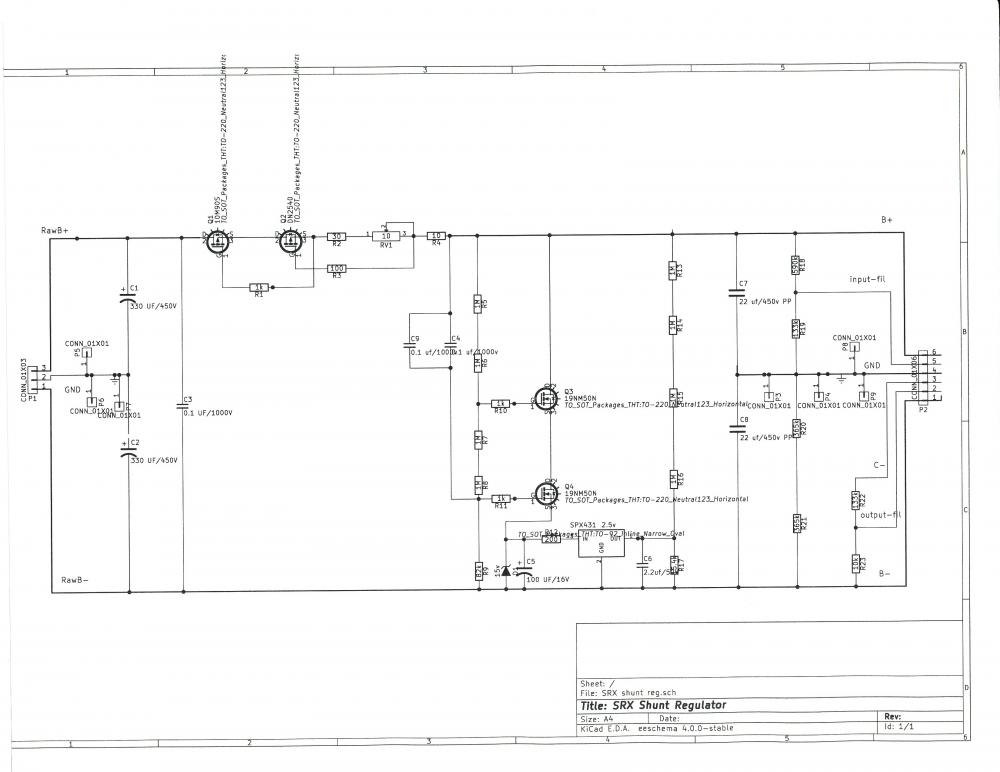
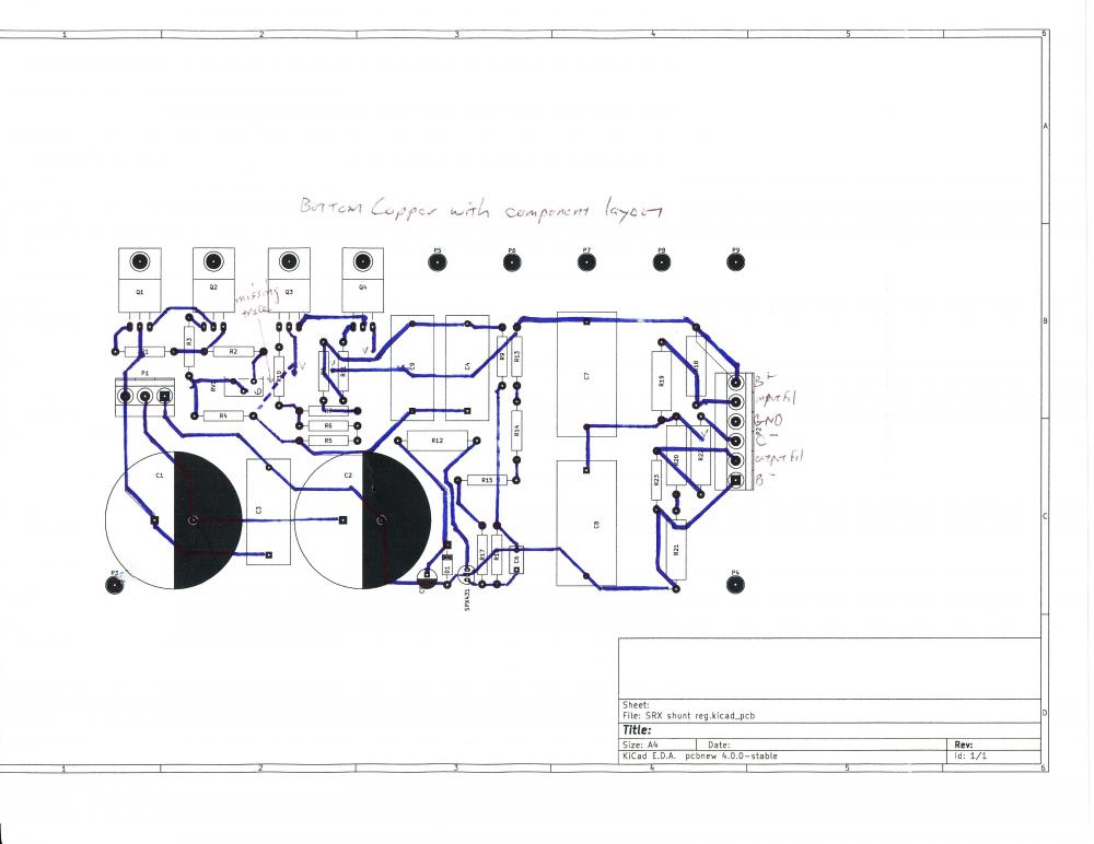
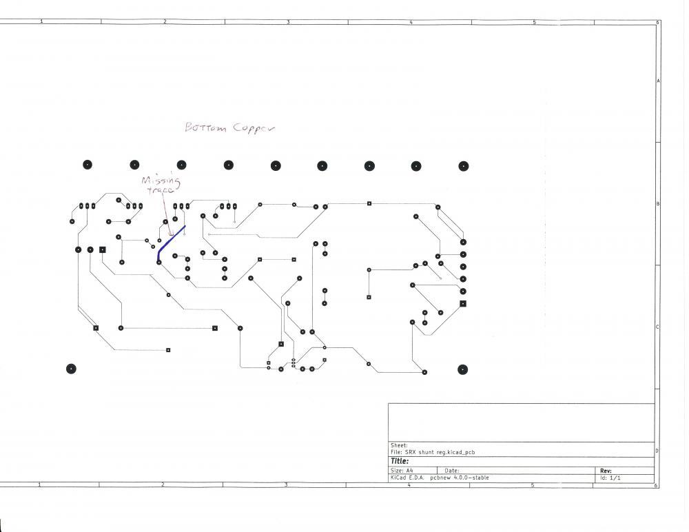
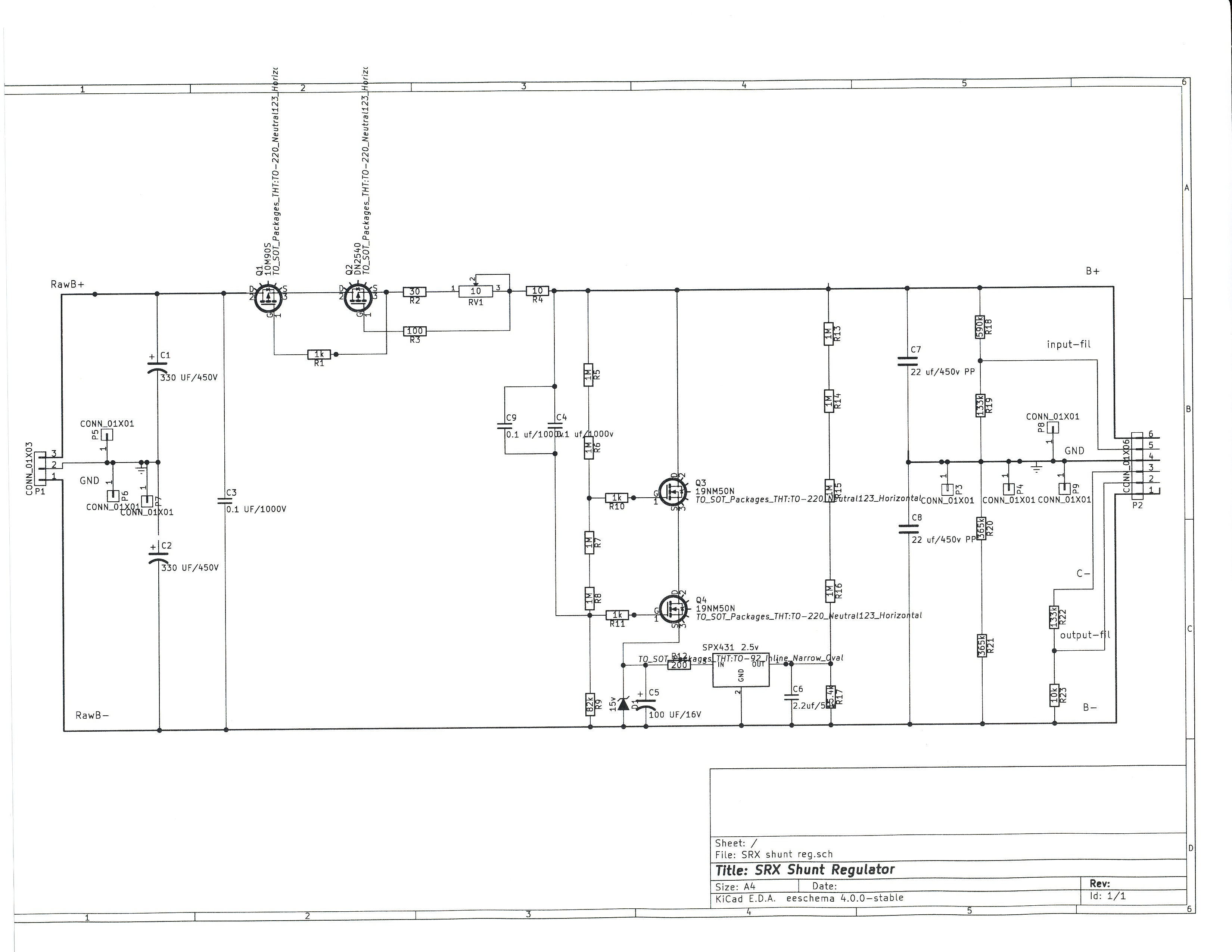
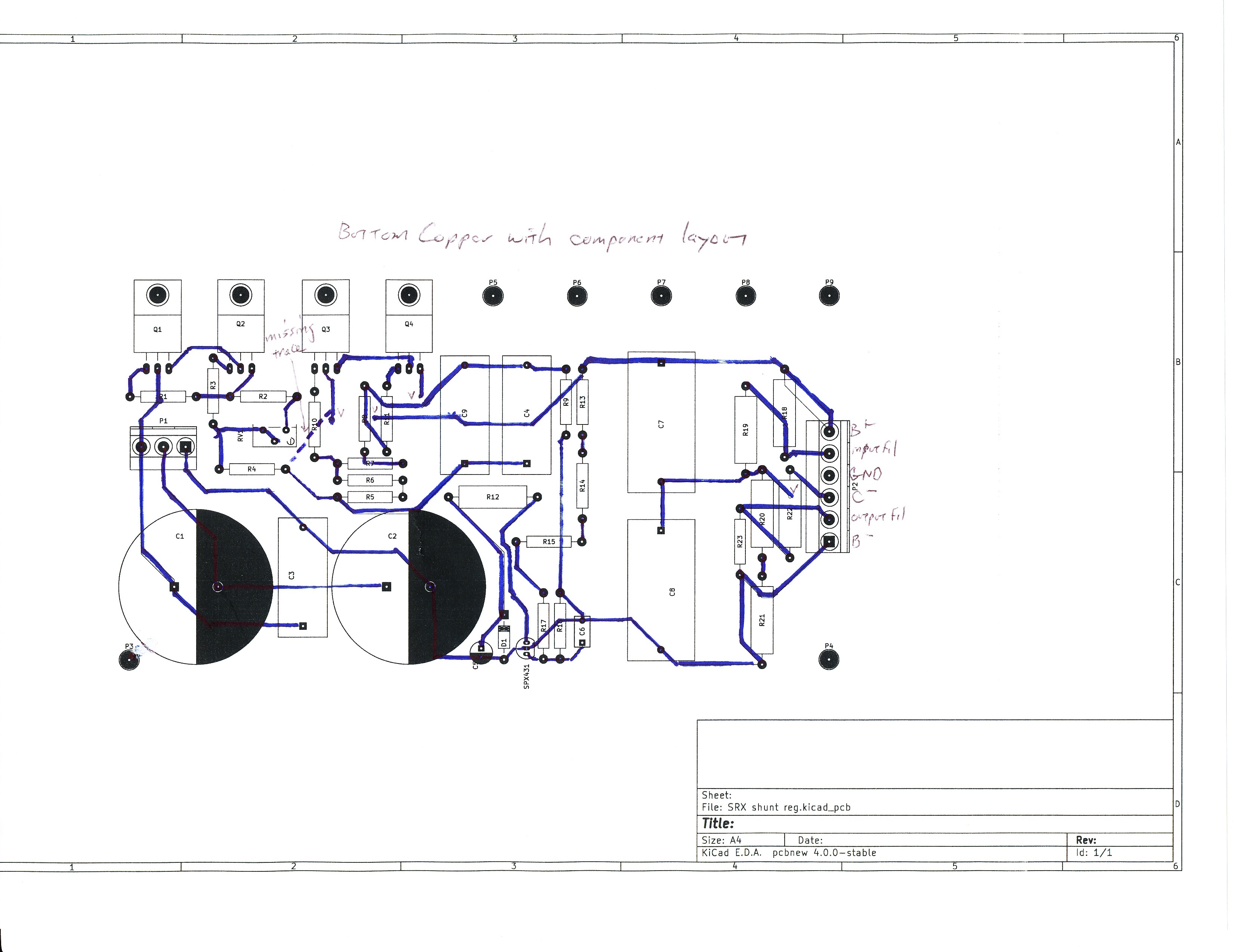
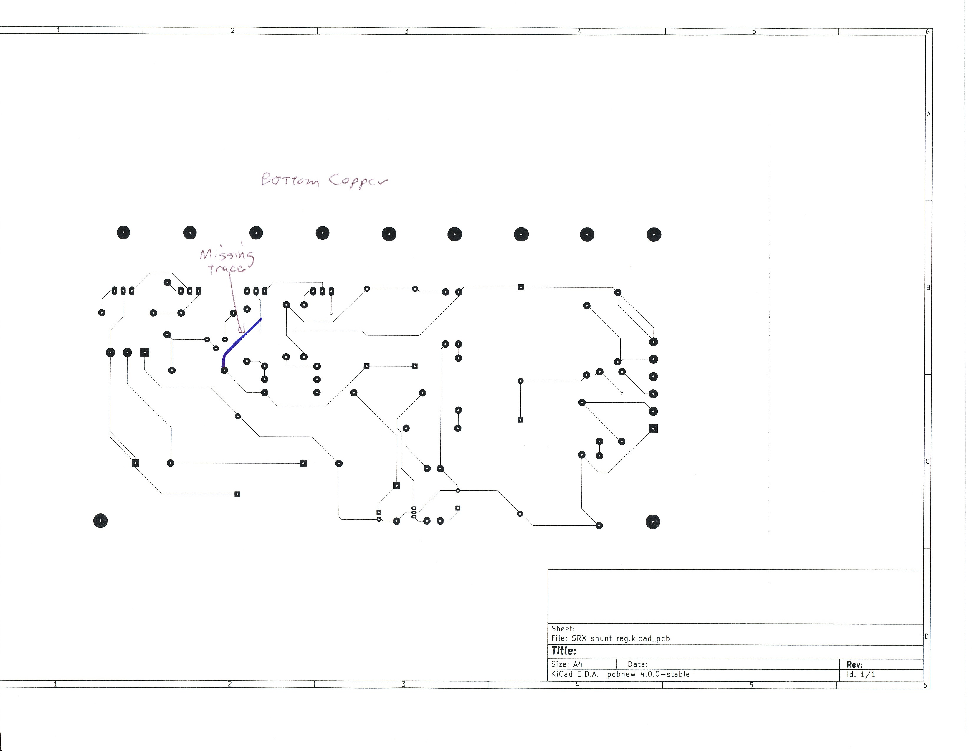
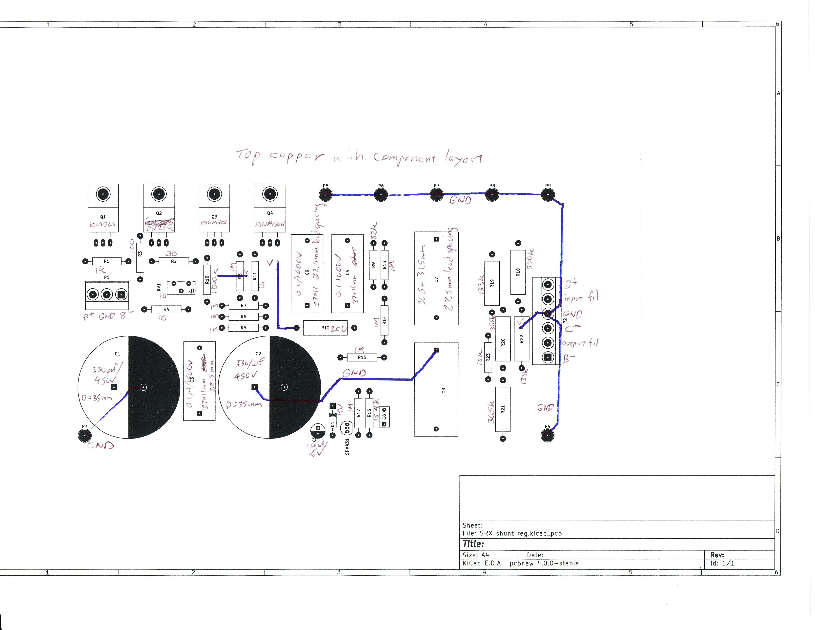
6 points6 points4 points4 pointsNice work Mike & Debbie! Looks beautiful and delicious. All I've got is pizza and Pliny.4 points2 pointsYum. I'm about to make buffalo chicken dip to add to our unquestionably unhealthy appetizers.2 points1 pointLooks amazing Debbie and Mike! All I had was pizza as well (but no Pliny or any other drink for that matter).1 point1 point1 point1 point1 pointPars, thanks for the offer, but if you haven't used KiCAD you're probably going to have at least as much trouble as I had. Dr. Gilmore, Thanks you for the very generous offer. Here are jpgs of the schematic, bottom copper with and without the component layout, and top copper. I believe there is only one missing connection. My layout uses an aluminum bracket because the MOSFETs should be able to withstand 35 watts or so if the amp boards go south and the entire current has to run through the shunt. Most of the connections are on the bottom copper, with two vias to the top copper, and a couple ground connections on the top copper which could be replaced with a ground plane on top. This is my first attempt at laying out a PCB so if you find a better arrangement feel free to change it. The 10M90S and DN2540 are available on Mouser, and I just checked that the 19NM50N MOSFETs are also available at Mouser, as is the SPX431. I chose those MOSFETs for their low on resistance, which is better than most, but other 500 volt rated MOSFETs can be used. So the input electrolytic caps are 35 mm diameter. The 0.1 uf/1000v caps (C3, C4 C9) are 27x11mm rectangular, 22.5 lead spacing The 22 uf/450v caps (C7,C8) are D-Link 36.5x31.5 rectangular, 27.5mm lead spacing C6 is 2.2 uf 50v R12 and R18-22 are at least 1 watt, 500 volt, other resistors are 1/2 watt.
 1 point1 point1 pointThe first of many questionably healthy appetizers for tonight. The Cheesy Buffalo Chicken Round. Sent from my iPhone using Tapatalk1 point1 point1 pointTHE BLUES AND THE ABSTRACT TRUTH 45rpm Impulse reissue Bill Evans, Roy Haynes, Eric Dolphy, Oliver Nelson, Paul Chambers, Freddie Hubbard.........Great, Great Record!!1 point1 point1 pointNice! I've been exploring dark chocolates recently, as well! Recent bars bought, and a box from Santa:1 point1 point1 pointSemi-relevant, I got these cuff links made from old watch movements for Christmas and think they are quite cool.1 point


Important Information
By using this site, you agree to our Terms of Use.