JoaMat
High Rollers
-
Joined
-
Last visited
Everything posted by JoaMat
-
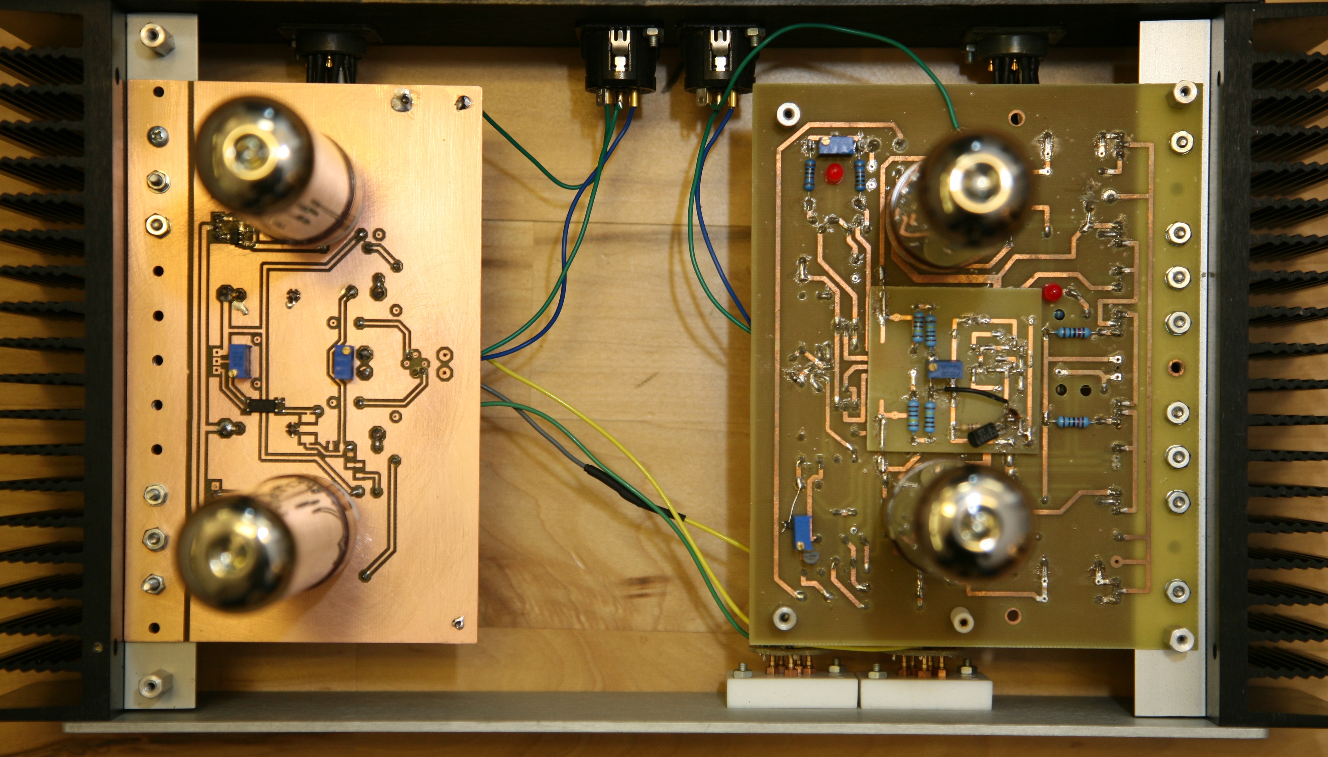
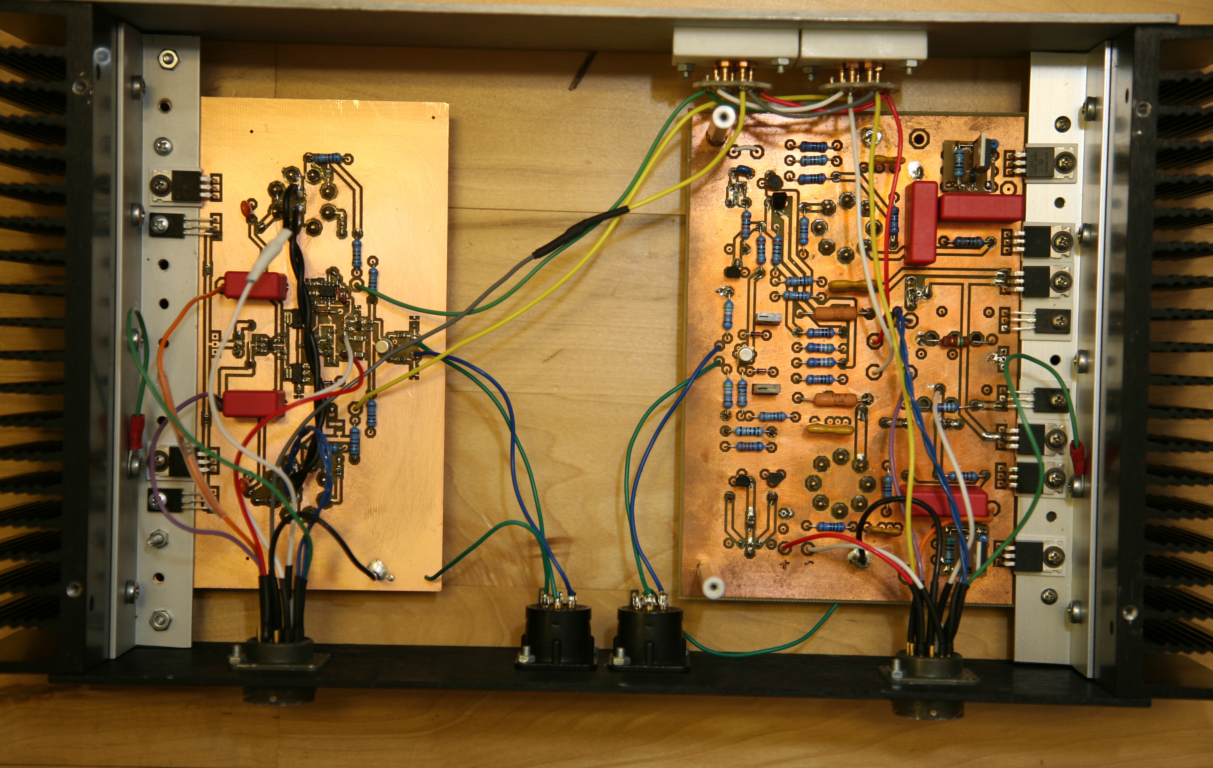
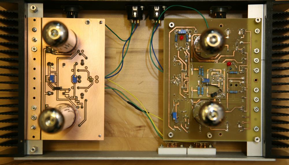
Left channel is a GG. Followed Kevin’s schematic. Intention is to use Emission Labs DHT, didn’t dare to test it with DHT so it’s populated with some modern less expensive EL34. Right channel is an old Blue Hawaii. The combination of BH and GG works terrific.

-
Have a great day, Wachara !!!
-
bdent.com seems to have a few in stock. USD14.29 each if you buy 25 pieces or more. You need 28 pieces?
-
If interested in the story of EL34, I recommend Guide to the EL34 / 6CA7 by Pasquale Russo.
-
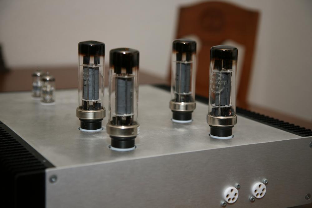
There are all kinds of EL34. Some good and some better. A few years ago I acquired those EL34. Probably manufactured in Eindhoven Feb. 1951(left) and Feb. 1954(right).
-
Birgir is most certainly right about KT66 and T2. EL34 and equivalent are the one to use. Regarding datasheet. Most of us aren’t competent enough to read them, including me. Anyhow I make a try. KT66 max working voltage is 500V and absolute max is 550V. DC voltage on output tube of T2 is about 450V. You will probably easily overstress KT66 and eventually maybe destroy them. If that happens – please let us know. I’m especially interested in effects on the amplifier. I’m sure that there are members out there that can tell us pros/cons KT66 with T2.
-
Beautiful!
-
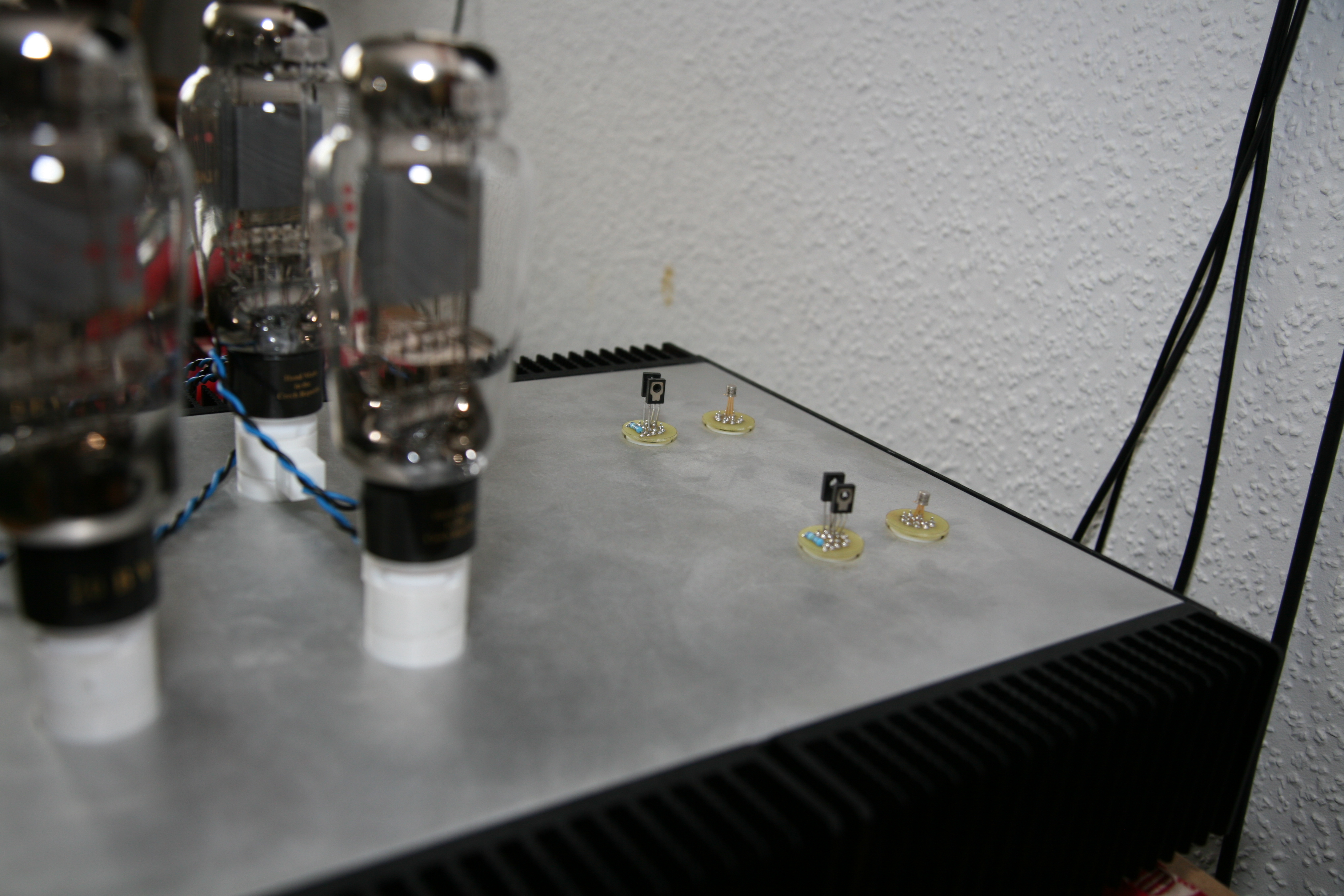
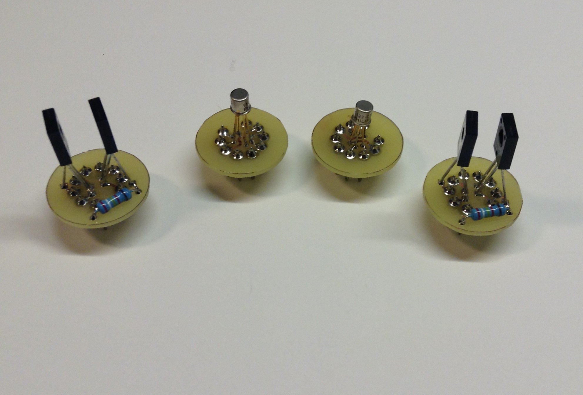
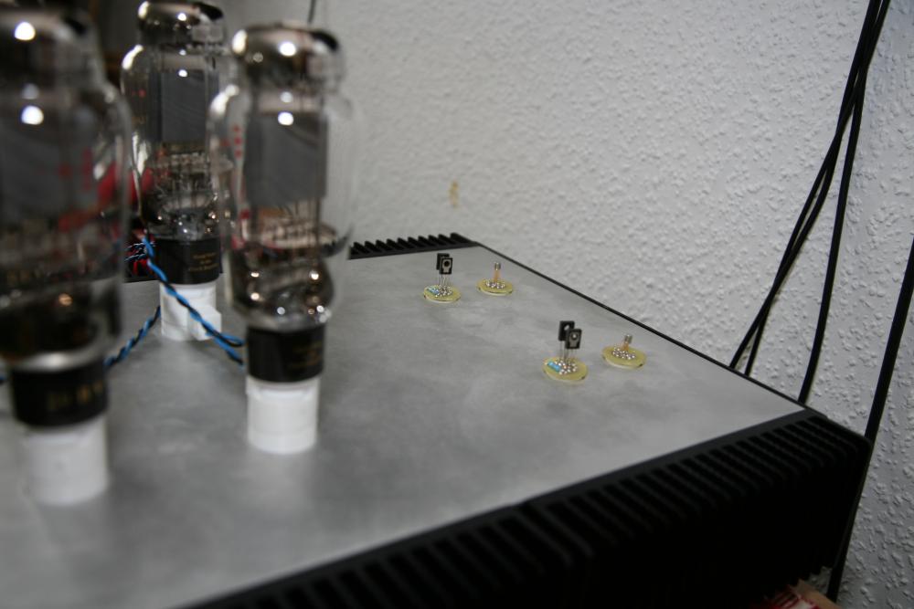
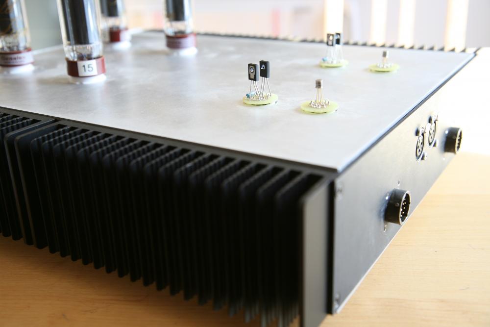
OK, now it’s done. Swapped the small tubes for solid state adapters. Kept +250V voltage and battery voltage unchanged. The 2SC3840 dissipate some 0.8W each. Might need small heat sinks. If you decrease voltage by 100V you also decrease power dissipation to >1/3W. And yes, they need covers. Working on it.
-
Didn't found heat shrink wide enough. So printed some covers for the connectors. Not so elegant but it serves its purpose. No, but now that you brought it up - well, why not.....
-
-
heat shrink, first thing in the morning.
-
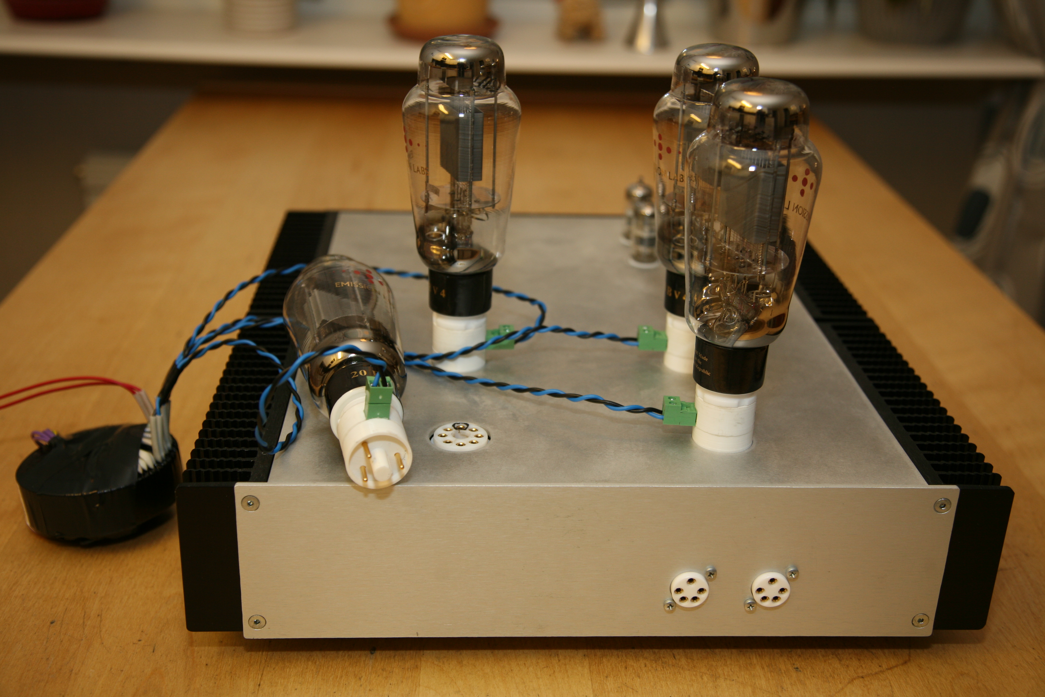
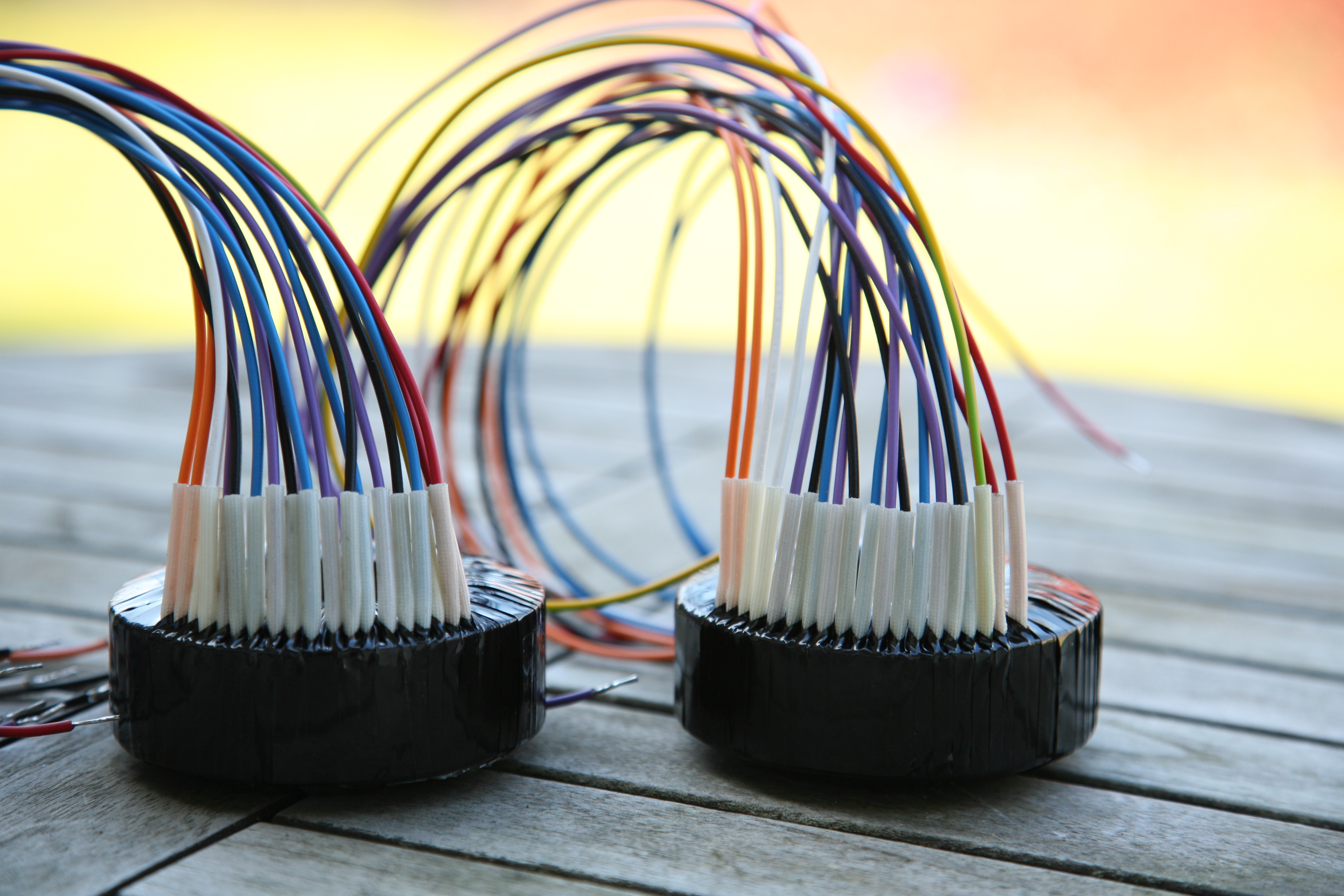
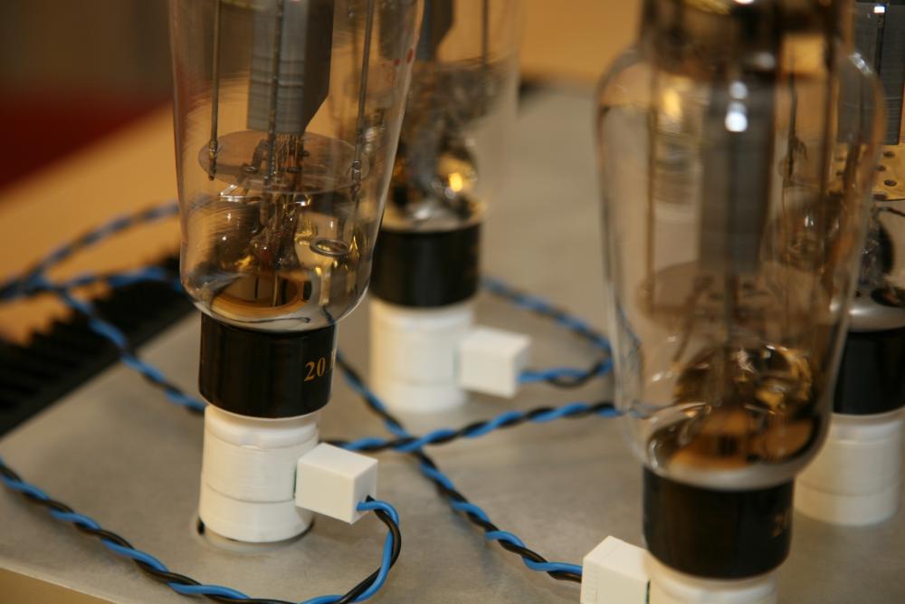
T2 with Emission Lab’s EML 20B-V4. Transformer to left is for filament 4 x 5.0V. Adapters are made by some help of a 3D printer, Teflon tube sockets, slauthered Neutrik XLR connectors, two pole male connectors. All held together with really good Loctite super glue.

-
-
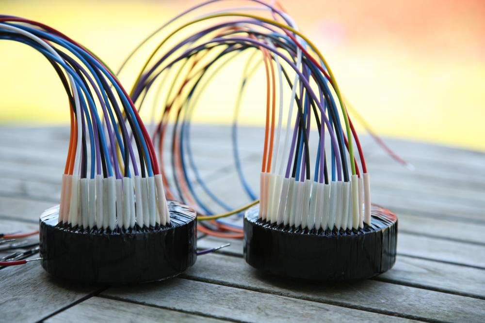
Pick a lead. Ordered transformers for DHT filament. Not sure the brain was involved.
-
This is what it looked like with adapter boards replacing the small tubes - ECC88/6922/6DJ8.
-
Only change to PSU was reducing +250V to +150V. For amplifier I changed batteries from 740V to 640V. Also the 68V grid voltage was reduced to 33V, but that is taken care by the resistor on the small board with two 2sc3840. Maybe one should build a modified T2 with lsk389 for input and EML 20B-V4 for output....
-
Made those a couple of years ago. All information you need can be found here.

-
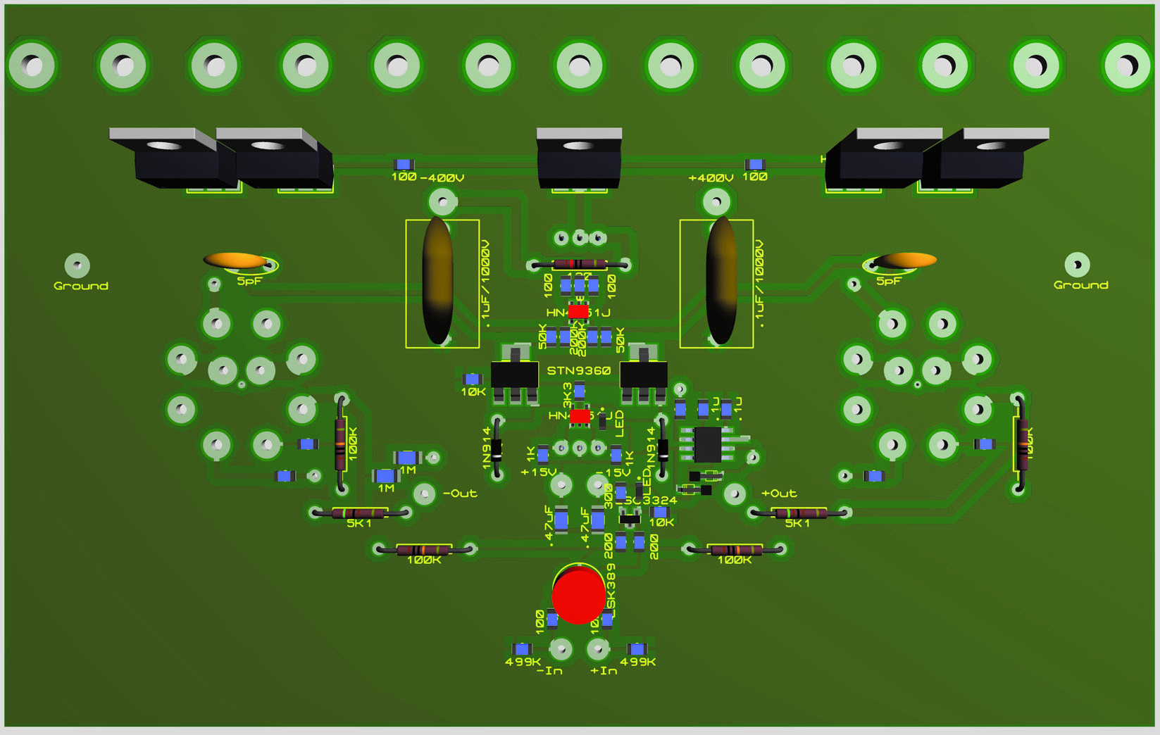
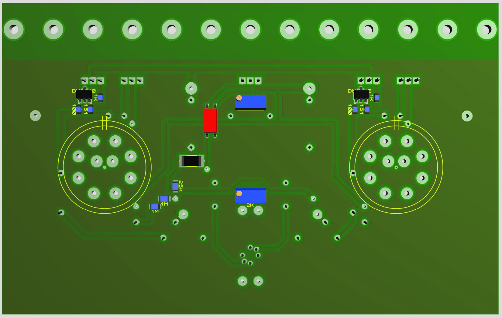
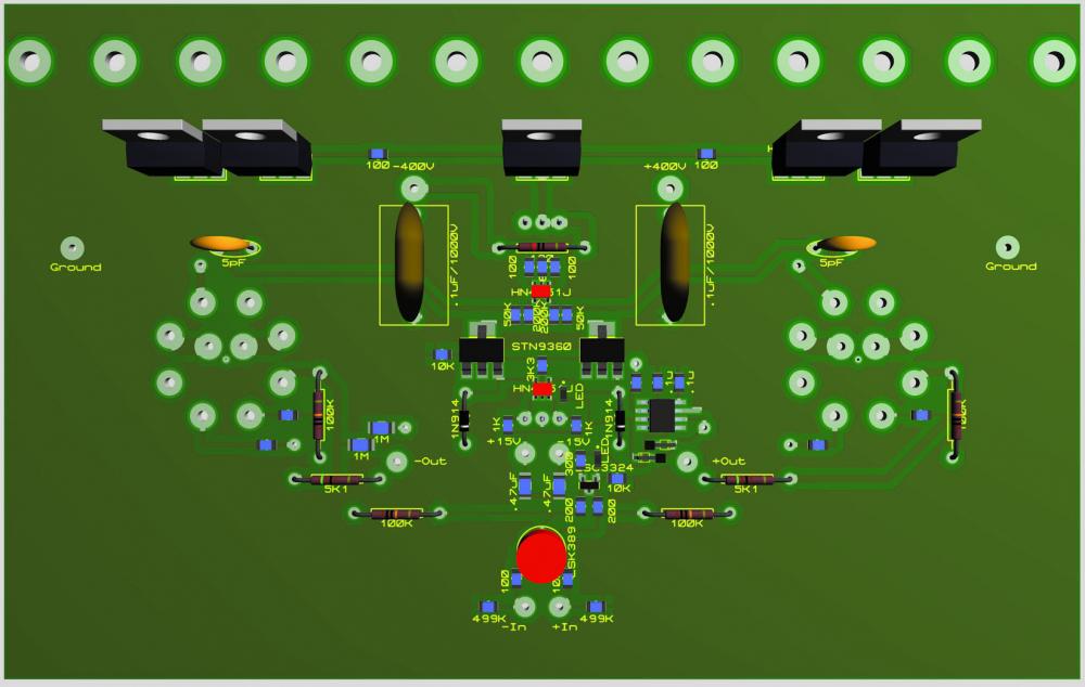
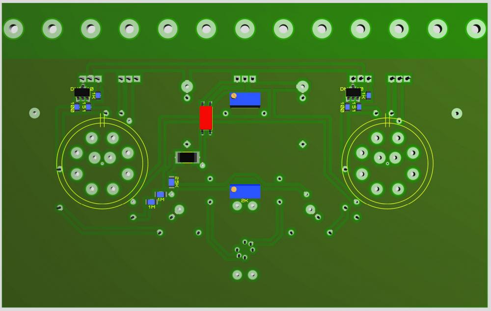
Have listen to the DHT carbon style for three weeks now. It’s bloody good – think I like it more than the T2. Below is a draft of how a smd version of DHT might look.
-
Thanks! Great have you guys around.
-
Regarding transformers and humming. Is it the transformer itself that hums? Or is it something else that hums due to the magnetics caused by the transformer?
-
-
Sold rk50. Got money enough for tubes, bottle of single malt and flower to wife.
-
EL60 is said to have the same characteristics as EL34 but it has 9 pin socket. The adapters are bought via eBay and quality seems OK. IMO EL60s are very good sounding tubes.
-
Nice connectors. I really like the color of the male. Help appreciated. PM sent.
-
Neutrik male pins, right? Can they be bought somewhere? Don't like to slaughter good XLR connectors to get them.