Pars
High Rollers
-
Joined
-
Last visited
Everything posted by Pars
-
I usually used TL071s on 15V rails, like all Dynalos.
-
How are you guys coming along on the production version Doug? I was just over at my brother's briefly yesterday, and he is still enjoying his immensely. Thanks for letting me in on the proto phase!
-
Tested it out this morning. A slight amount of tube hiss (barely audible with head < 12" from speaker), but no hum. Gone at all gain settings. And this is with the tubes cold, so it should decrease after a bit of warm up. I need to publicly thank Alan (VivaVee on diyaudio) for his help in finding this. He is the same person who helped me fix my brother's power amp as well. Good guy.
-
Please fix that! Make it stop, please...
-
Looks decent. I don't have any experience with them, but Ayoue seems to be well thought of. Price looks good as well. I would think this would be much easier than the flood and suck method, particularly in clean up Another plus for being able to localize the heat rather than having to heat the whole board up (toaster oven).
-
Happy Birthday Colin!
-
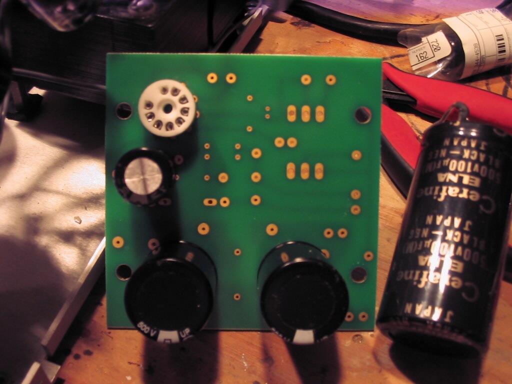
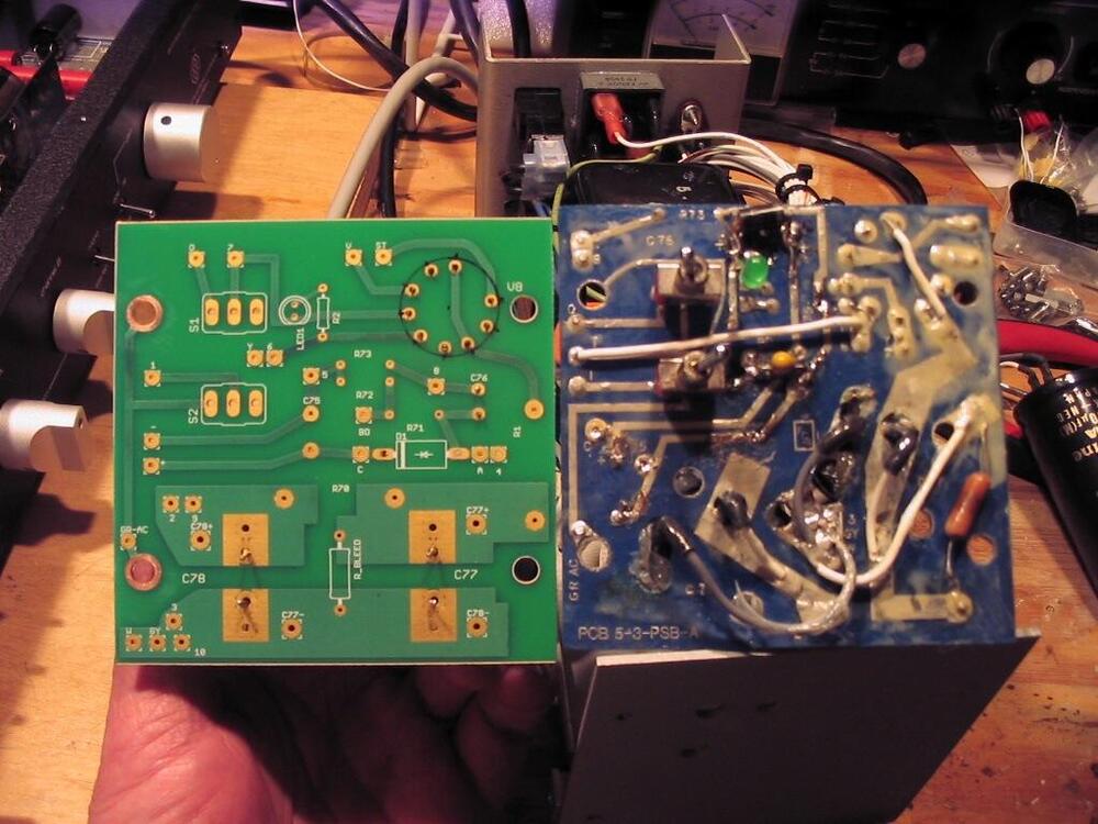
Still trying to decide whether to swap out the PCB with one I did a couple of years ago. Looking it over again, it has a couple of minor errors on it, but I think I can work around them. I didn't check the stock tube layouts in Eagle, and this turned out a bit small on the pad circle. This socket will fit, but I'd rather use the Azuma socket that is in there now, and it doesn't fit. I also don't think I will put the two 500V Cerafines like the one pictured in, but will use the Panasonics pictured on the board. The old board is coated with Q-Dope... not dirt http://i883.photobucket.com/albums/ac31/Pars1746/Counterpoint%20SA5/new_PSU_PCB.jpg http://i883.photobucket.com/albums/ac31/Pars1746/Counterpoint%20SA5/PSU_PCBs.jpg

-
Happy Birthday Steve! Glad I didn't open this thread at work
-
Looked like that to me too, curled up on the sigma22... it doesn't run THAT hot! I see you have the AA HPA in prominence as well still
-
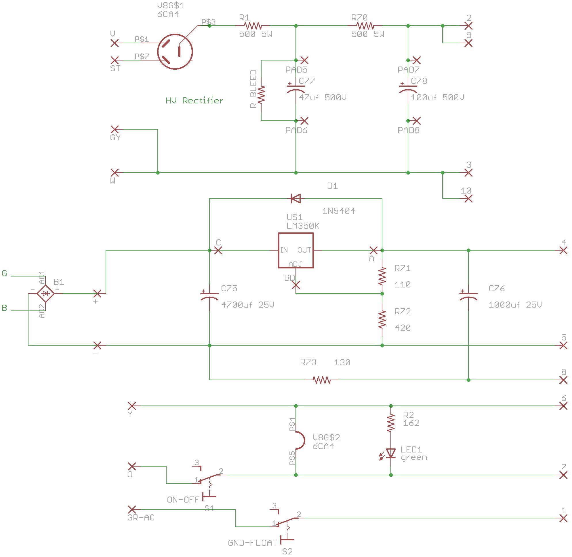
Sorry, fresh out of scotch Probably good advice. Point to point isn't likely to happen in this given the form factor (think '80s Threshold preamps with their brick PSUs; then think of stuffing a full tube pre and tube rectified PSU into that form factor) and resale value, so I pretty much have to deal with what I have. Corrected (for the .1 version) schematic
-
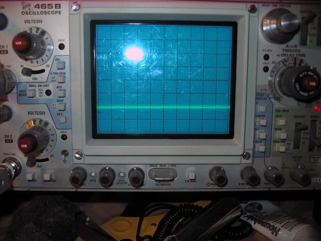
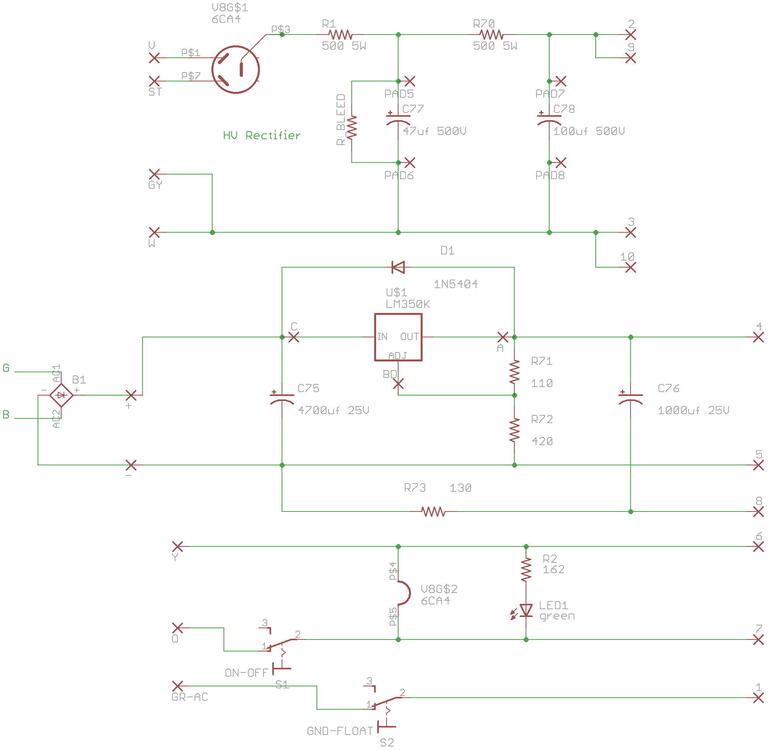
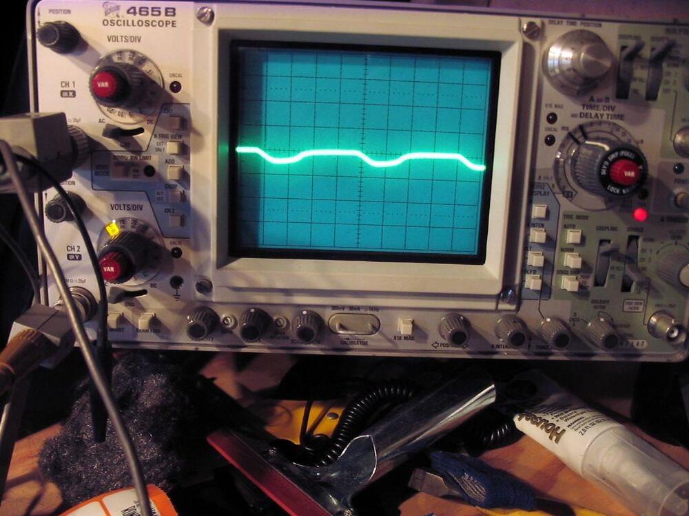
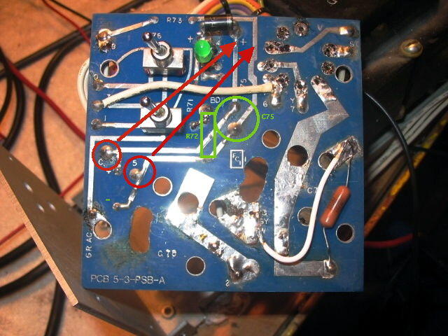
I've been messing around with a Counterpoint preamp I have owned for several years on and off. It's always had a slight amount of hum, not real bad, but it bothered me. Over the years I've managed to make it worse, and then much better, but never quite gone completely. After dealings with a couple of former service techs on diyaudio, I finally decided to try once again to rectify this. I was prodded to look at the PSU, particularly the heater supply (I'd already done some work and parts replacement in the HV section). Looking at the heaters, I had recalled seeing some ripple on them back when I rewired the umbilical (both before and after). About 50mV of ripple at 2x line frequency (120Hz). 50mV/division (x10 probe). After being pointed in the direction of board layout, I noticed the following (once it sunk in): C is the lead to the input of the LM350K regulator. It is wired right next to the input (+) from the bridge rectifier, putting raw DC in. Moved to past the filter cap (C75). 5 is the output (-) to the tube heaters in the amp chassis. It is also wired prior to the cap (C75) One more change not shown in the pic: R72 (green rectangle shows location) needed to have the bottom end rotated 90º counterclockwise so it returned beyond C75. After making these changes, the net result: Same 50mV/division, timebase is extended out a bit in this pic. Designer seems to have a problem common to many: PSU design. And this is a high-end preamp from the '80s, lauded by Arthur Salvatore, yada yada. Such simple errors, but it surprised me as the changes involved moving components/wires along signal paths that are unbroken and electrically connected. The previous connections weren't wrong, they just weren't really right. Noise was being fed into the regulator because its feed was taken before the filter cap, not after it. The output (pin 5) was also being taken before the cap, not after. Same with the adjust pin return resistor (R72). One other thing not done originally: per the datasheet, the addition of a 5 cent capacitor across the adjust resistor buys you 15dB better noise rejection. Implemented now. I haven't listened to it yet, but anticipate that it should be gone

-
Mike, I really like the one you posted in #20236. What is it? Resco?
-
Happy Birthday to both of yaz!
-
Last time I heard the CSO or any live performance, natural sound includes bass. Not sure what you are getting at above? Plain bass? Never heard the term...
-
I'm sure there are some other owners here.
-
Good you found a fix other than a new transformer!
-
ditto on the CD... might D'L the WAV and do it myself until then though.
-
Happy Birthday! :prettyprincess:
-
-
Good first (or 2nd?) post. And yup, props on the initiative. Hope it is a successful meet.
-
Congrats all around as well! And sorry about the car door, that sucks
-
There is a pop up menu (pulldown I guess for windoze) on the bottom left that controls IP.Board or IP.Board Mobile. I would guess you want the Mobile?
-
^ or a statement to how spoon-fed things have gotten. The pics of "go here" were a bit over the top.
-
The Dynalo servo was supposed to be able to handle 50mV, but in my experience, even asking it to handle 20mV is a problem (though 20mV really isn't a problem for most headphones anyhow.) I prefer to get offset well inside of 5mV or even +/-2mV before throwing the servo opamp in, but that is probably just me being anal. In the original dynalo, offset was dealt with via LED substitution and resistor selection for the CCS's. Justin's V2 (and I presume V1) boards also did offset reduction this way... not sure what tolerances Justin did his production boards to or how he even handled this. This was rectified on the Dynahi boards by including the trimpots paralleling the CCS resistors. I know that it would take the servo awhile to do this (as you stated in your posts with digger), probably on the order of 5 minutes to stabilize. It would seem that selection of parts (R55, maybe R19/R20) could balance this out, but maybe not. BTW, I found and am using a single pin connector for the outputs on this (and the dynahi) which might be useful to GB members. I can't find an equivalent at Mouser though. These require drilling a hole in the PCB, but that isn't a problem. And they will fit even with all output devices populated on the DynaFET. These are JST XH series: header: 455-2227-ND CONN HEADER XH TOP 1POS 2.5MM housing: 455-2220-ND CONN HOUSING 2.5MM XH 1POS pins: 455-1135-1-ND CONN TERM CRIMP XH 22-28AWG
-
As the testing progresses, one of my observations is a DC offset delta of ~160mV between the two feedback settings. This obviously won't work for anyone wanting to switch between the two (at least without some readjustment). I'd be curious to see what others note on this as well as any adjustments to parts values that would close this gap to 0 ideally. I'm using 2K for R19-R20, 3.3K for R17-R18 and 1K/100R R55 / R56. I think it was about the same with 1K/221R R55/R56 as well. EDIT: didn't see the above before posting. Yes, I'm not a fan of PRPs coating, but haven't gotten any mismarked (yet).Coating seems more like vinyl than epoxy, at least in it's durability