jamesmking
High Rollers
-
Joined
-
Last visited
Everything posted by jamesmking
-
Pars, I entirely agree about the seperate thread for GRHV. Almost all 680uf 550V and even 500V caps are 80mm high - too high to fit into a 2U chassis (for example mouser lists some 500V less than 80mm high but none are stocked items, for 550V 680uF ALL are 80mm) . I also like the kemets for their life expectancy (although they are not cheap). I put 550V into both positions simply because at some point I might reuse the power supply and change its output. If you are budget conscious the output caps can be 450V or 500V for 400V output. This is one of the cases where moar does not always equal better. The kemet caps are very low ESR and so the inrush current from the GRHV quite considerable - with 470uF caps its enough to weaken a 3.15A slow blow fuse to the point where after 10-30 switchons the fuse can fail. 680uF is going to be even worse inrush... This also puts more strain on the power supply transformer. For example, on my mini T2 with GRHV supplies the high inrush chokes the HV transformer and results in it humming for quite some time, I don't get this problem with the kgsshv on my full T2 (despite the fact the full T2 has 25% more idle power consumption) because kghsshv in it has even less capacitance and so less in rush than the GRHV... I have not done a listening comparison between 680uF and 470uF. For me the only considerations was space and reliability.
-
Seriously, don't run the bias at 645V and dont run bias through a DIN plug....
-
moar voltage is moar good... everyone uses +580V bias voltage why?... convention, lack of imagination, no willingness to innovate and because its easy! No one knows the origins of this "standard" few dare to question its validity... True leaders and visionaries dare to be different and go that extra electron or two even if it cost more and requires more engineering. 645V is clearly moar than 10% bigger/better than the conventional "standard" everyone lazily adopts. 🤪 the fact this can be achieved in such a small amplifier is even more testament to next level, next generation engineering effort put into this remarkable amp. Occam clearly stated that perfection is reached not when nothing else can be added but when nothing else can be taken away. Look at the size and complexity of the full T2 (but then it uses valves which are obsolete technology, environmentally unfriendly, dangerous inefficent space heaters) and even the behemoth that is the T2 cant manage to reach the bias voltages of this seeming humble and simple amp. This amp is Occams razor in its purest form. Who else would dare to run bias voltages through a 5 pin DIN plug? they said it could not be done, they said a DIn plug is not rated for more than line level voltages... they were wrong, just as they were wrong about the +580V convention. This amp is just full of innovative and convention breaking, ground breaking, diaphragm breaking and heart breaking design choices. ... and next week a stax amplifier based on a dual 741 opamp with zero feedback powered by energy harvesting the heat from a T2 or megatron..
-
T2 first listening impressions. wow..... erm.... wow..... erm..... wow The first thing that strikes me is marco dynamics are amazing, on recordings that are not that dynamic the amp does not exaggerate the dynamics, but on dynamic recordings like full orchestra the dynamics are so powerful but not overdone. This is backed up with bass is far more defined, less mushy, more full than my other stax amps but the bass is not not dry or hard or overblown Stereo images are more solid and tangible and more precise than any other stax amp I have, its so close to the experience my Quad 2805 speakers..... Detail is amazing, but the detail is not thrown at you and its therefore not tiring to listen to. But I do notice tape edits, dropped violin bows, musical score page turns more... but it just adds to the experience that tens of musicians in a room can't be totally silent all the time. when music gets complicated there is far less tendency for sounds to just clump together into a messy mushy ball. However you still get the feeling of musicians playing together and the detail is not analytic. The amp just says here is all the detail let it wash over you and you decide how much you want to listen into the detail and how much you want the whole music. This is the first time I have been satisfied with the bass and dynamics from my sr007a mk2. I think it shows that my stax sr007a just need as much drive as they cant get. My journey: stax srm006 (piece of mushy yet bass light and less bass the higher the volume, undynamic, undetailed, poorly constructed, stereo thick soup, gloop with the sweetness of a lemon), hi-amp alpha centauri (improvement in every way over the srm06, its an upgrade but you still feel there is music missing. Overall you get the impression is nothing special and has but poor bass, slightly deeper than the srm006, but mid and upper bass is almost non existent. Bass loss with volume is far less), blue hawaii (murders the alpha in every way but maybe slightly hard sounding for me and a bit of a tiring long term listen. It was a very enjoyable build and a considerable step up from the alpha but I rarely could relax into the music), Mini T2 (better micro dynamics, smoother and more refined more listenable than the hawaii but lacking in some drive and macro dynamics, detail and bass. I still got the feeling with it that it was struggling with the sr007s a bit) and finally the T2 (im sure I will eventually find something wrong with it... that's just the way my brain works but for now im content [which is rare])... So whats next after the T2? (other than building a second one).... Many many thanks to Kevin for the T2 and joamat for the modified T2 and mini T2, spritzer for providing the nos transistors and everyone for their encouragement and help.
-
try not to kill the user until AFTER they have finished paying for it Equal rights for electrons! they should be allowed to travel freely and not be constrained by insulation... If they want to travel through your heart it just their way of being loving and friendly.... they are so misunderstood.
-
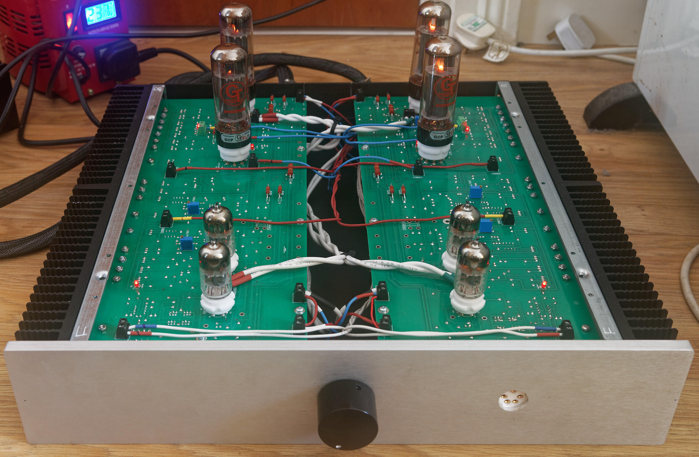
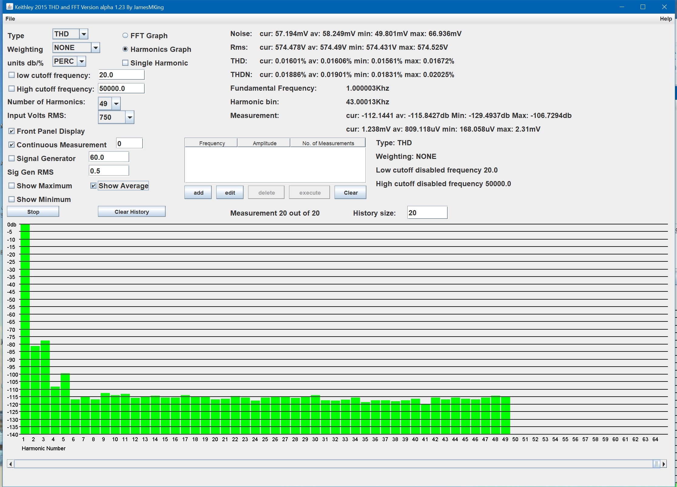
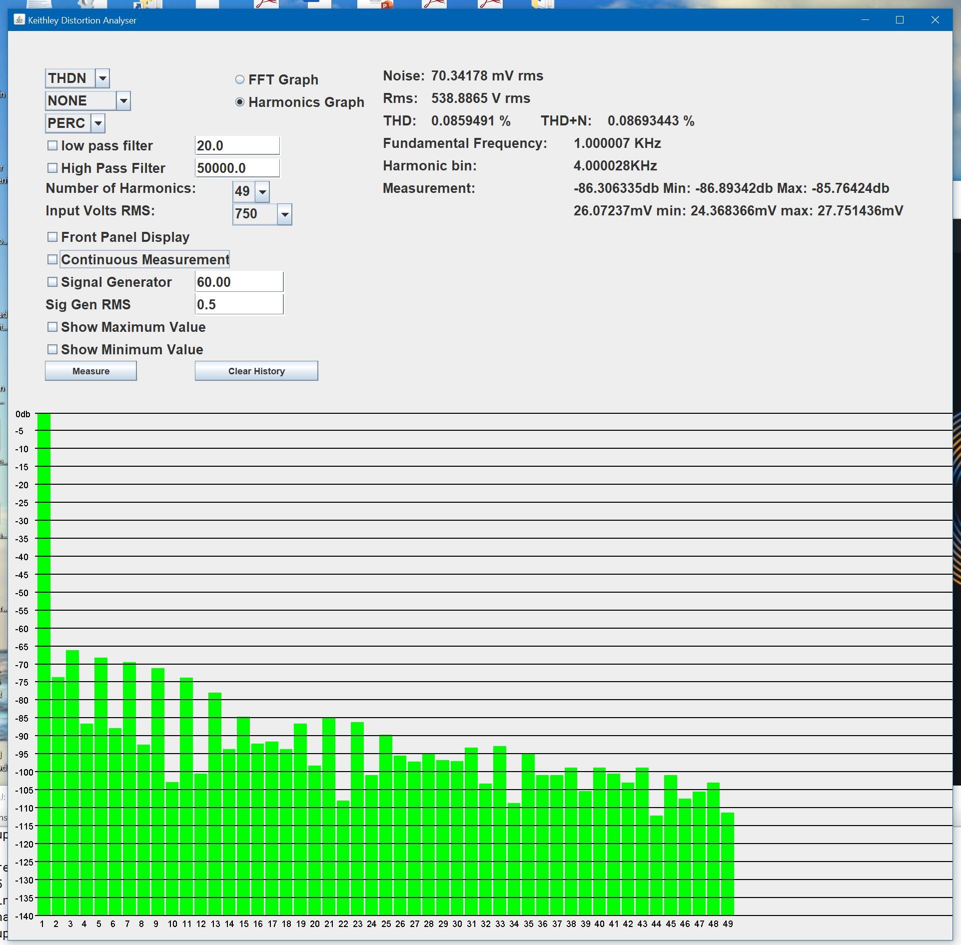
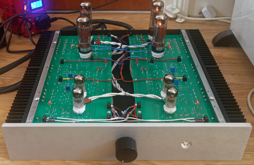
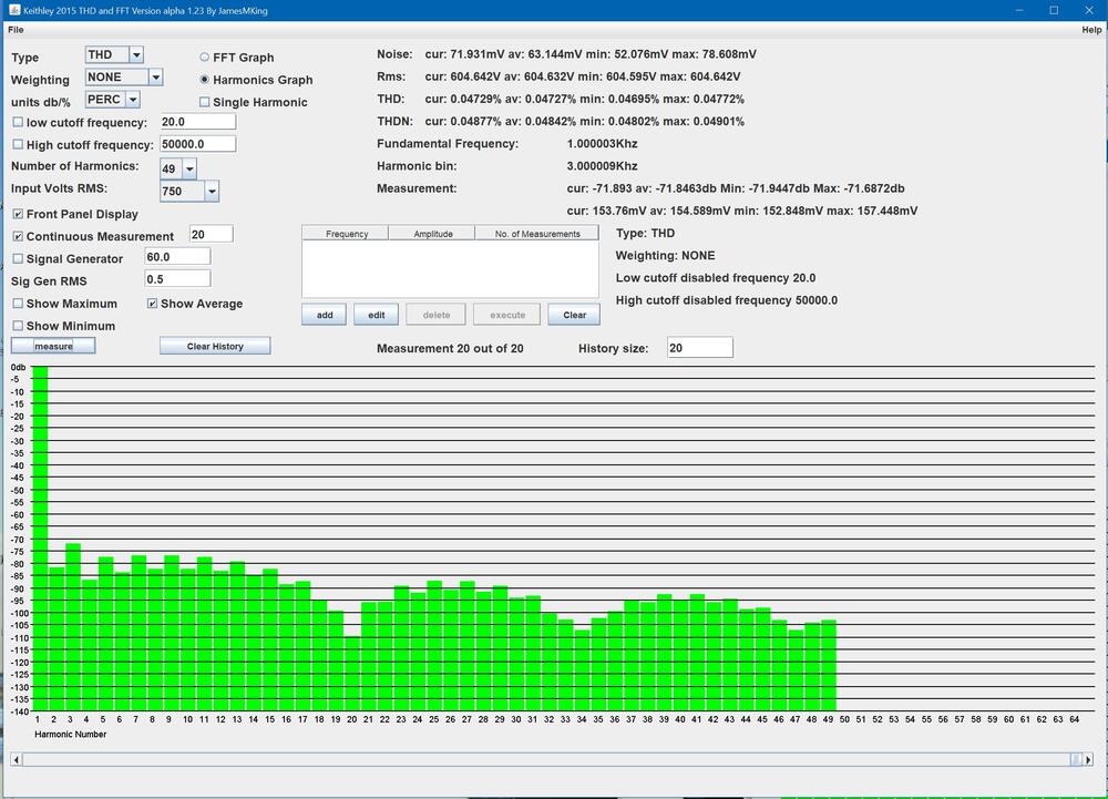
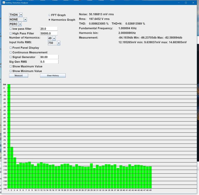
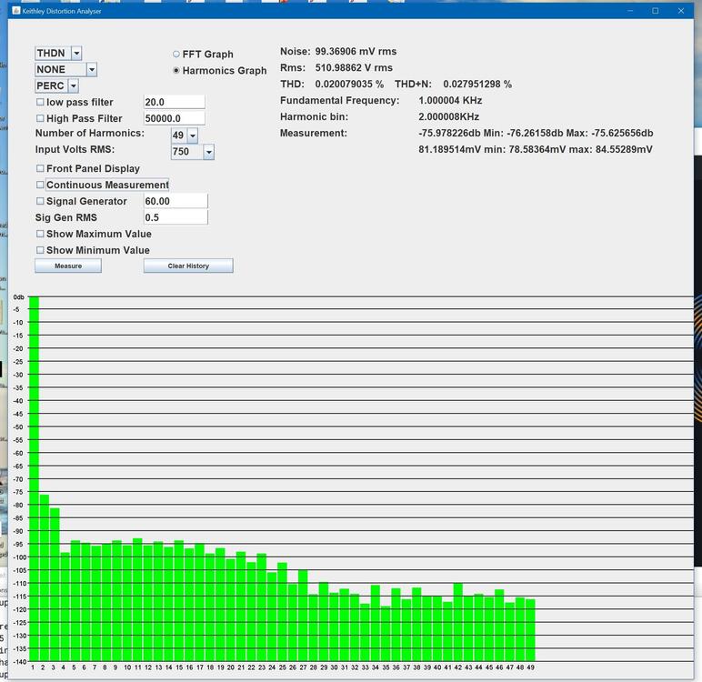
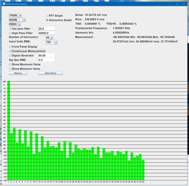
listen to it? if you check my todo list nowhere does it say listen to it... measure it yes... listen to it? why would I do that? 🙃 latest update, internal signal wiring done (silicone not cardas - I need to buy more cardas chassis wire) and front panel completed. Both channels powered up at the same time for the first time. No drama so far. The heatsinks around the el34s runs a bit hotter than joamats mini T2. I not done any temperature checks look good. All transistors seem ok and so do the high power resistors. .6922 heater voltage is a little high at 6.35V so I will need to add some dropper resistors. All other voltages are spot on. El34 heaters are at 6.1V which is about the same level as my mini T2. I found my first issue, the DC balance between + and - halves of a channel is fine <50mv BUT the DC offset to ground started at -85V and even adjusting the offset pot all the way I only got it down to -33V. Exactly the same on the other channel due to close matching of components and matched valves. So I will need to replace the dc offset adjustment trimmers with something 2-3x the range. Anyway I know you have been waiting for the money shot: glowing leds and heaters so enjoy: Im currently going for an extended power on idle test and will be periodically checking voltages and temperatures on both the amp board and psu. If that passes it will be time to feed it some test signals... I hoping for more detail in the square waves, more dynamics in the triangle waves and smooth fatigue free sine waves. Here are the first measurements. Distortion 1Khz input Total Harmonic Distortion to 49Khz is around 0.0063% unweighted (average of 20 measurements) 2nd harmonic is around -90db and third slightly higher at -87db. The other harmonics are very low all less than -105db. total harmonic distortion plus noise is better than 0.018% (im not using shielded cables for this test AND the amp and psu do not have top lids and the cases are not grounded so the amplifier is almost certainly has better thd+n than I am measuring in this setup. At around 575V rms 5th harmonic starts to rise and at 600Vrms output all harmonis increase and odd order are higher than even order harmonics. NOTE this measurements where taken with around 35V DC offset so it is possible clipping may occur a little later with less offset... Noise, THD, THD+N and level of distortion harmonics at 575V RMS, 1Khz output: Noise, THD, THD+N and level of distortion harmonics at 600V RMS output 1Khz: The THD up to 49Khz is still less than 0.05% The amp runs quite a bit hotter than the mini T2, heatsinks near the EL34s run at 40C and power consumption is close to 205W. The mini T2 is around 153W. The power supply is also is less efficient than the golden reference HV, the 3W resistors between the ksa1156es and ksc5026 run close to 90C and dont have a lot of room around them, on one side there is a large 0.1uF 1KV film cap and on the other 5 closely packed transistors... So the T2 needs good heat sinking and the psu boards could do with lengthening a little to give the 3W resistors a little more air flow around them and drill holes under them. Update DC offset fix, The 5K pot in parallel with the 510 ohm emitter resistor gives a minimum resistance of about 461ohm which still gaves me ~ -33V offset. With the 5K pot in the middle you get around 423ohm combined resistance and ~ -85V offset. So I replaced the 510ohm with 604ohm and this gives enough adjustment range to get <1V DC offset. (I would have implemented joamats suggestion but I did not have any 10K pots)

-
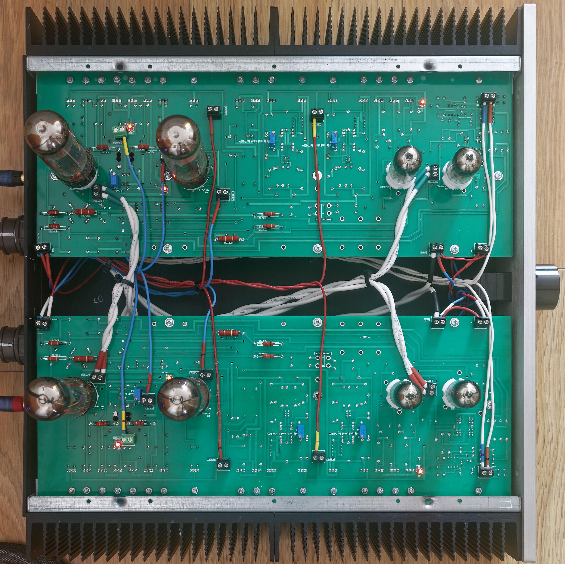
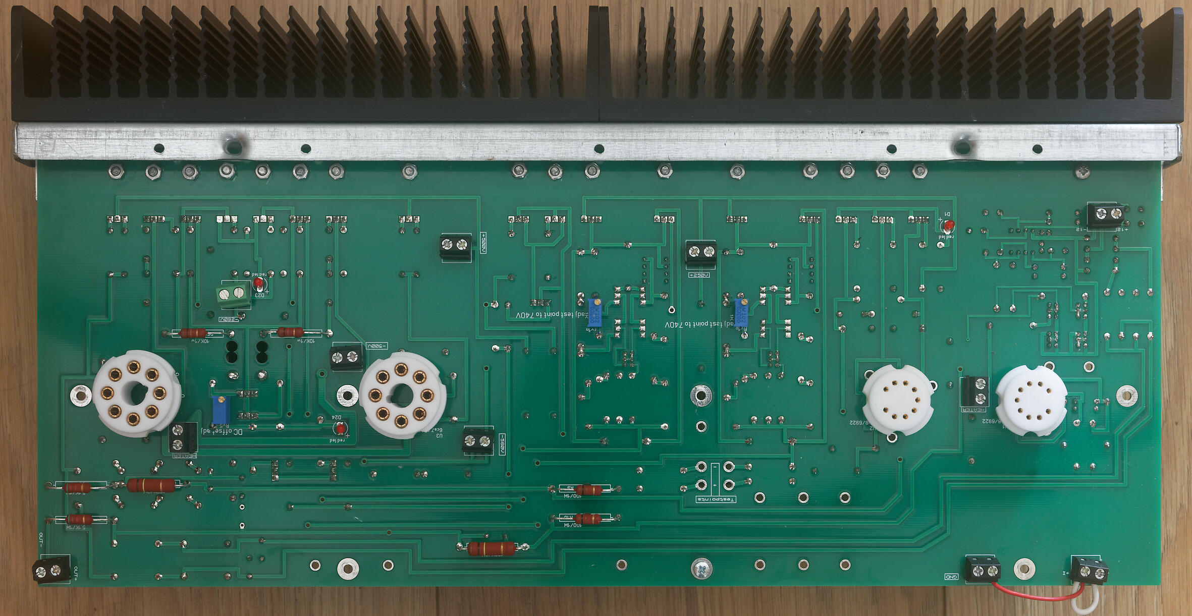
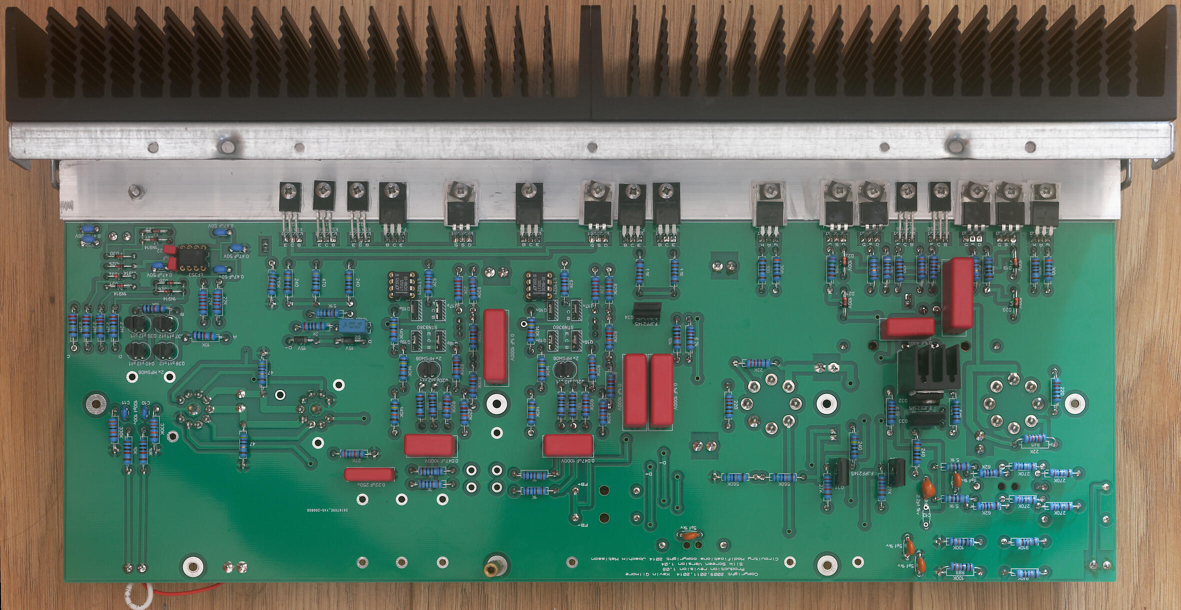
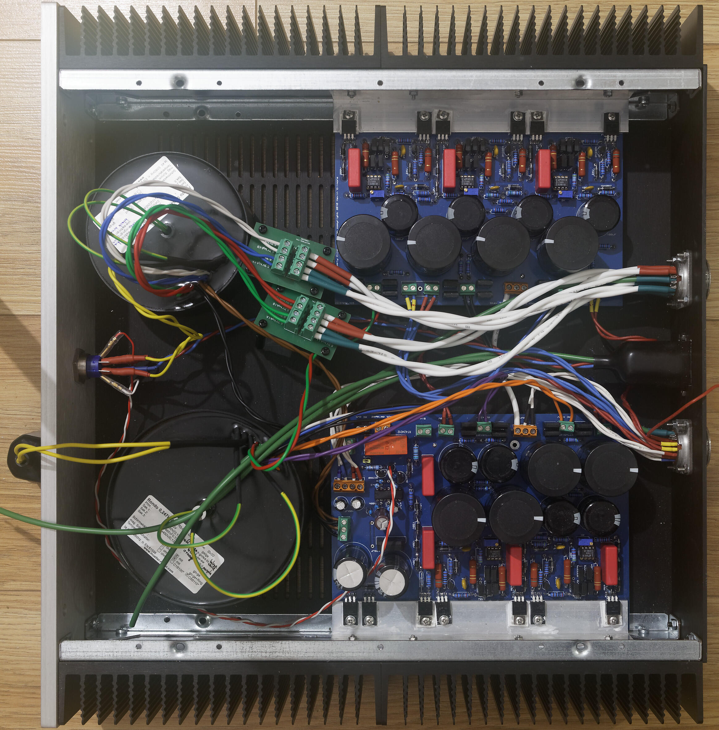
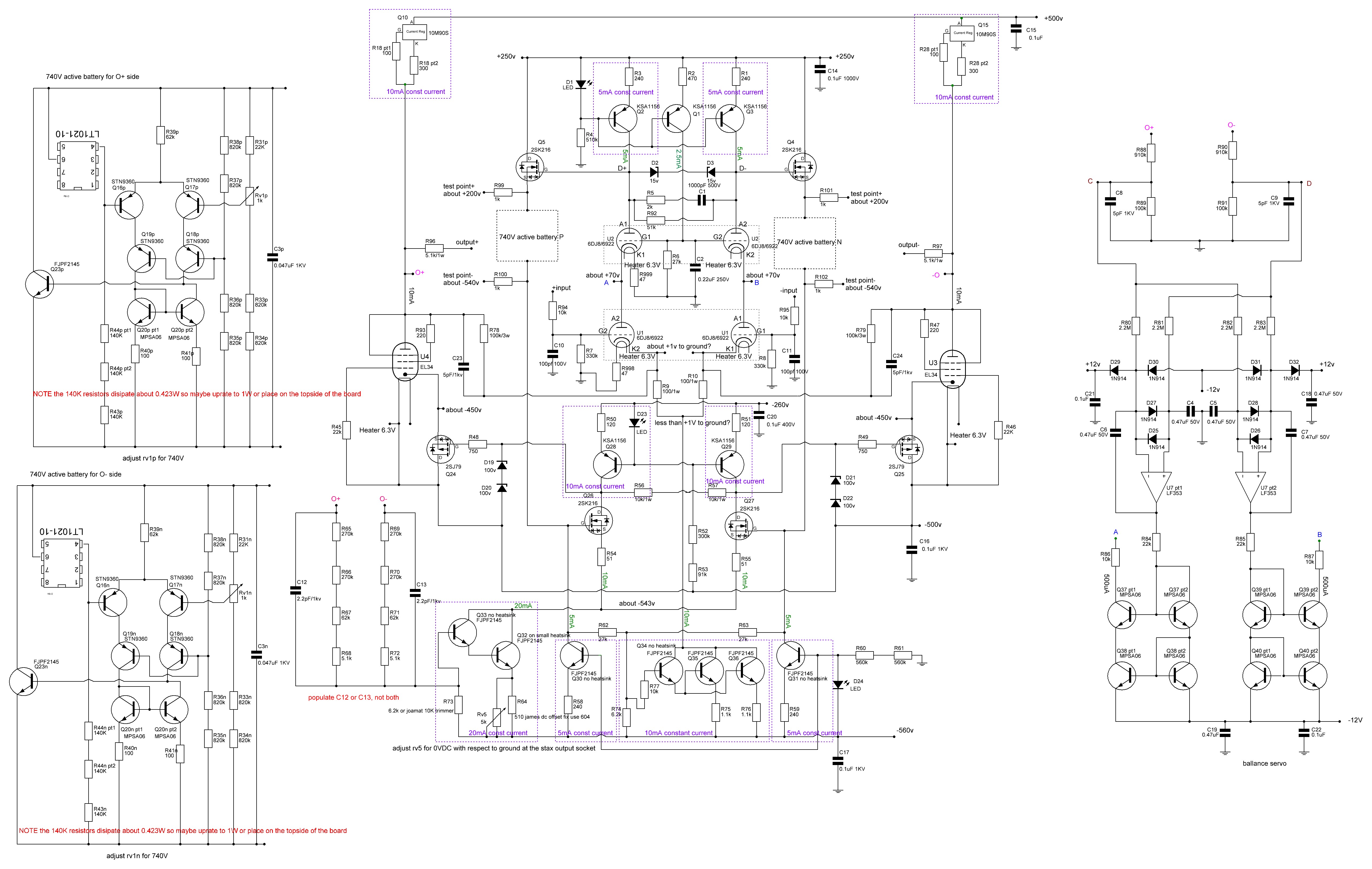
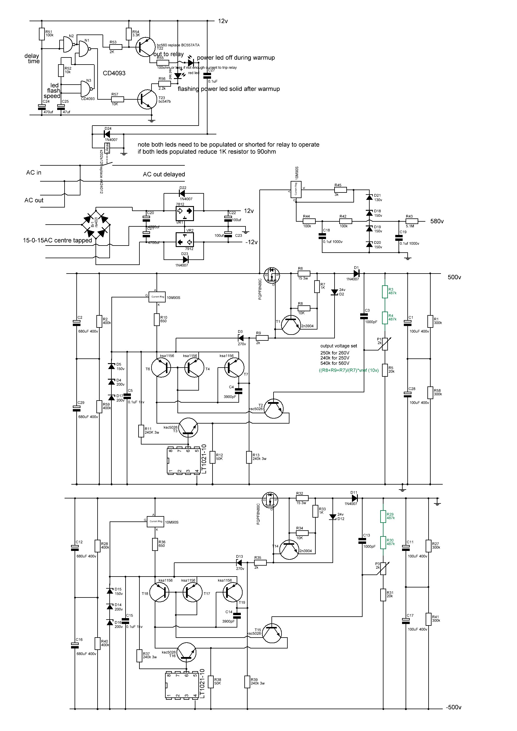
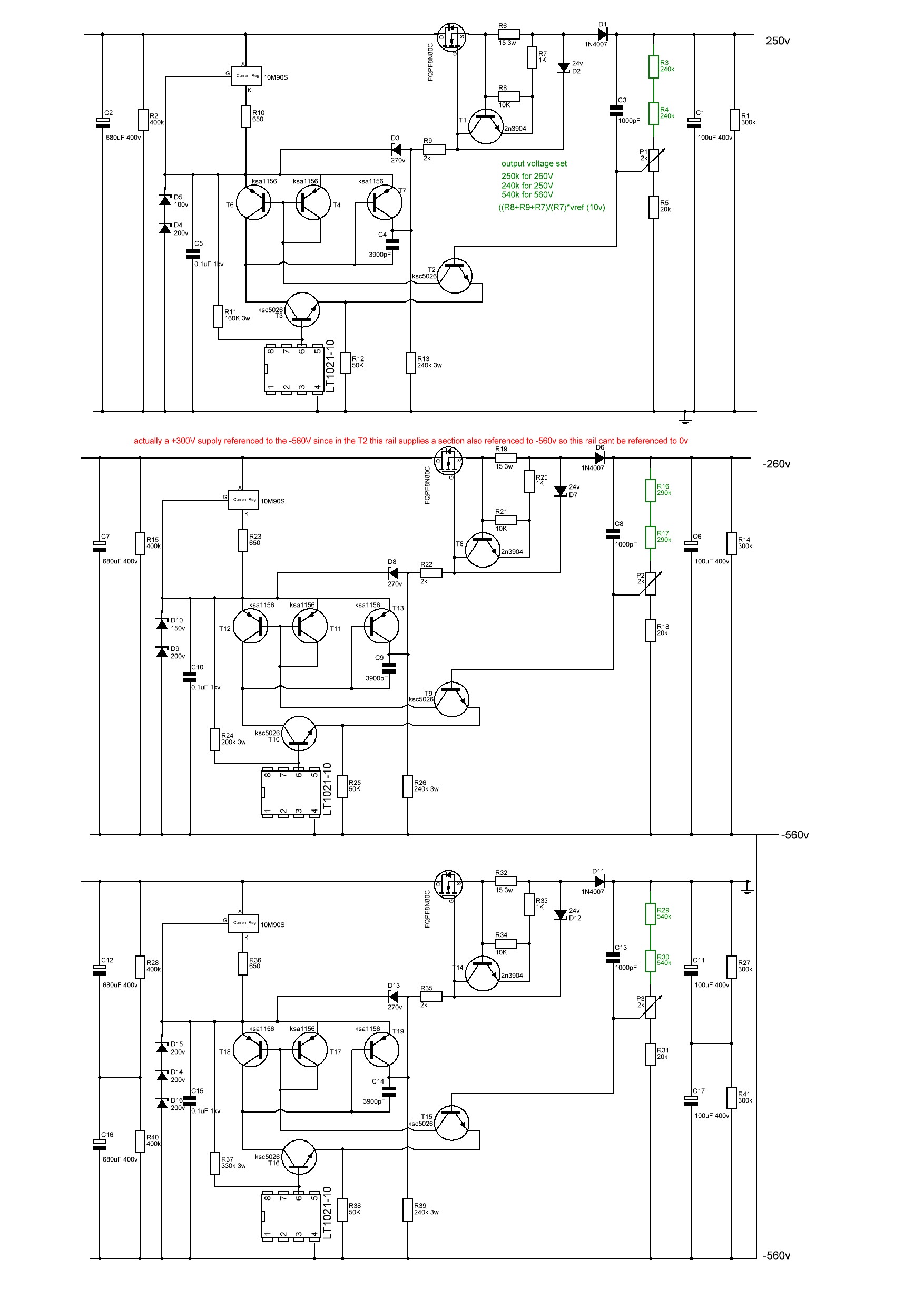
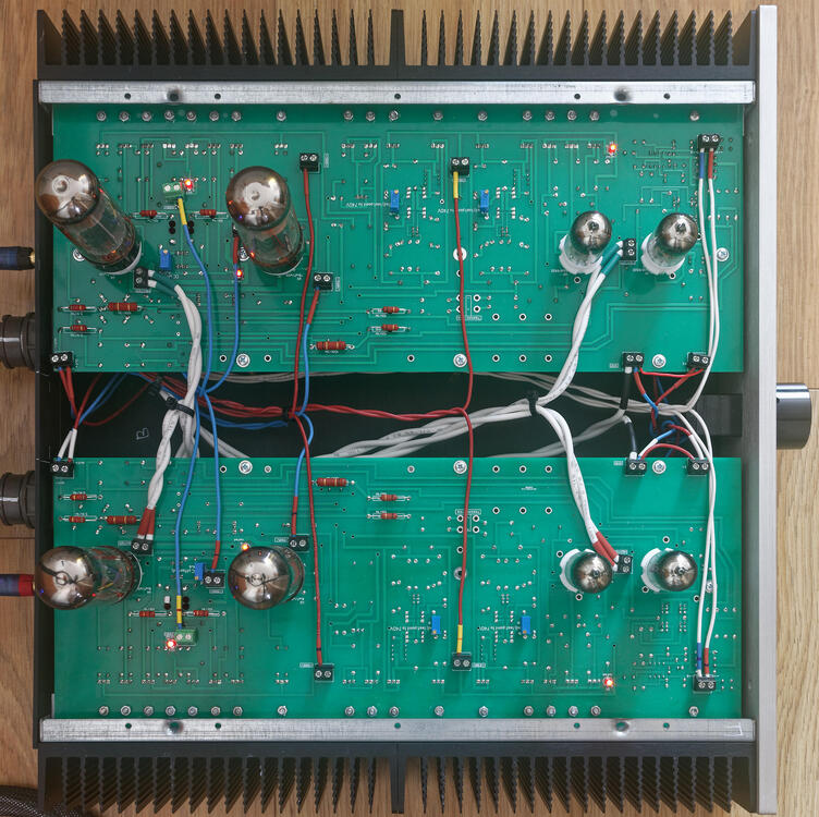
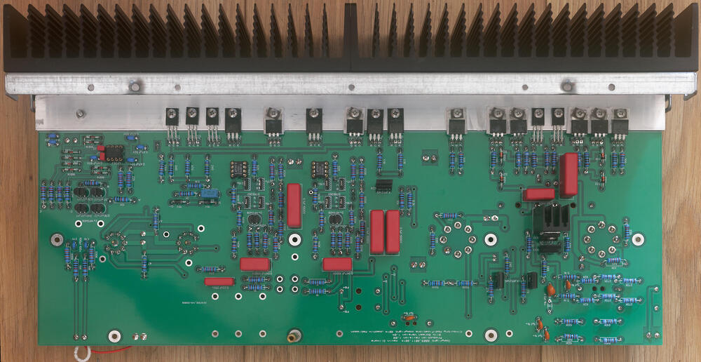
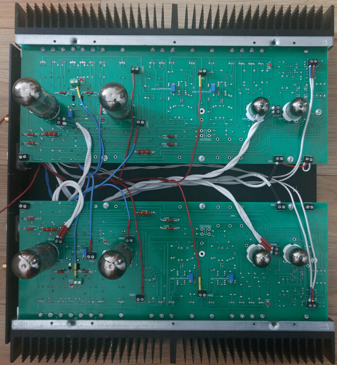
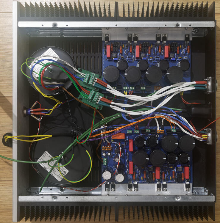
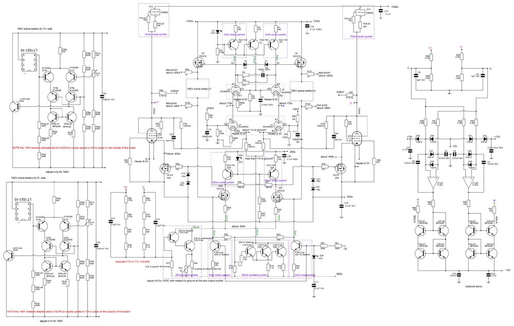
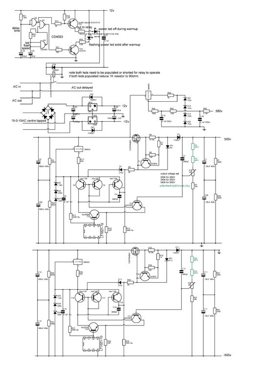
It might be a little premature but I think I now have a working T2 using a modified version of joamat's staxt2nc3fdh7 amp files and kgsshv dc supplies.... Initial startup looks good. Channels started up seperately. Heater transformer running at full voltage. High voltage transformer on a variac. virtual batteries within 100mV of 740V before any adjustment. DC balance between + and - sides of a channel <1V without any adjustment, all 3 leds lit on both channels. once my hands stop shaking I will take a few photos... I have been dreading switch on... in the meantime here's a few build photos of a finished amp channel top and bottom, the amp and psu I modified the delay circuit on one of the psu boards to use a relay instead of the now unavailable solid state relay. I modified the amp boards so that 1. they fit into a 400mm deep chassis, hifi 2000 dissipante chassis. 2. they have screw terminals for all connectors on the top.. (less neat but easier for testing and rebuilding) 3. all resistors of 1W or more go on the top of the pcb with a drill hole under for increased airflow 4. groundpane is between 1.1mm and 1.3mm from any solder point 5. pcb is cut in half so each channel can be built, tested and mounted independently, 6. solder points for pot and input jacks removed and replaced with screw terminals. 7. silkscreen has instructions for adjustment of pots 8. mpsw06 transistors replaced with mpsa06 9. small standalone heatsink for Q34 FJPF2145 in the 20mA current source darlington pair has drill holes in the pcb by the fins for enhanced airflow. 10 all components have schematic numbers included in the silkscreen 11 leds and adjustment pots mounted on top side of pcb like the original T2 12 removed the bias input and 5.1M resistor (since the kgsshv psu already has the resistor in the bias section) I will be happy to release the gerber files of my modification once I am certain the amp is reliable For the build: wima film capacitors, mixture of koa cm1/2 and xicon 273 series 1/2W resistors, for higher wattage vishay pr02 and pr03 All resistors, diodes, zeners raised from the pcb. pcb 2mm with 2oz traces. All 1/2W resistors matched to 0.1% or better at 1khz on a good LCR meter between + and - sections of an amp board AND between left and right channels. all non psu and psu decoupling caps matched to better than 1% at 1KHz on a LCR meter between + and - sections of an amp channel AND between left and right channels. (except for the pF caps which are just too small to measure accurately). all leds and mpsa06 transistors matched on a dca75 curve tracer between + and - sections of an amp board AND between left and right channels. all zener diodes matched to within 1% or better between + and - sections of an amp board AND between left and right channels. separate umbilical cords for AC heater power and DC voltages all internal wiring 1KV silicon all signal wires will be cardas chassis wire volume pot tkd 2500 series left to do install rca signal wiring, volume pot and stax output socket test with signal generator and measure distortion etc collapse from T2 build anxiety drill top of case for valve sockets clean up wiring pray to the god(s) of electronics sort out grounds on psu post moar pictures Here is the schematic for the staxt2nc3fdh7 NOTE this is my reverse engineer based on the pcb and the original T2 schematic and has not been checked by anyone. ( as far as possible component labels reflect the original T2 component labels. In the case of 2 components replacing a single component in the original T2 the components are now labeled Xpt1 and Xp2. In the case of additional components no present in the original T2 they start with the number 9XX. In addition both batteries are shown and the the components labeled with a Xp for the O+ side battery and Xn for the O- side battery. Note the 140K resistors in the virtual batteries dissipate 0.423W each and I found xicon 1/2W 273 series discoloured and drifted by about 1% after about 6 months heavy use when placed on the underside of the pcb. So you may want to think about 1W resistors or place the resistor on the top side of the pcb. psu low voltage, bias, +500V -500V and hv delay reverse engineered from pcb and original schematic. not checked by anyone. psu +250V, -260V and -560V reverse engineered from original schematic and pcb not checked Note psu schematics changed 22/08/2022. Thank you to Rinat for spotting an error on the current path around the 3900pF cap.


-
The headphones are only made of organic materials and grip the head well, however they do have a tendency to slide around a bit and my ears got fairly slimy rather quickly. I am concerned about long term life expectancy and batch to batch consistency. I may have received a faulty pair, connecting them up to my blue hawaii resulted in the drivers crisping up very quickly. The ear cups are also quite fragile and have a tendency to crack if dropped.
-
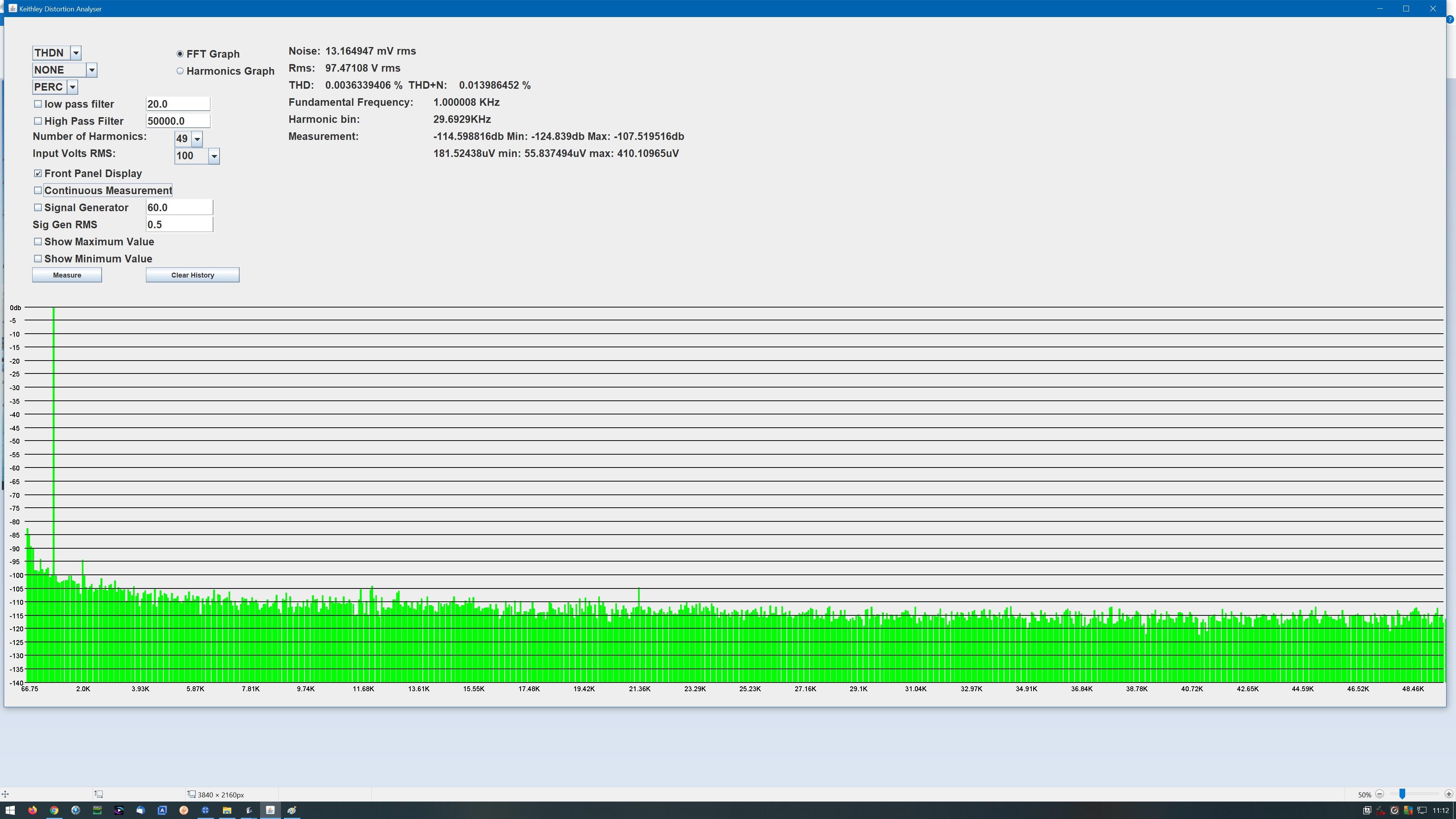
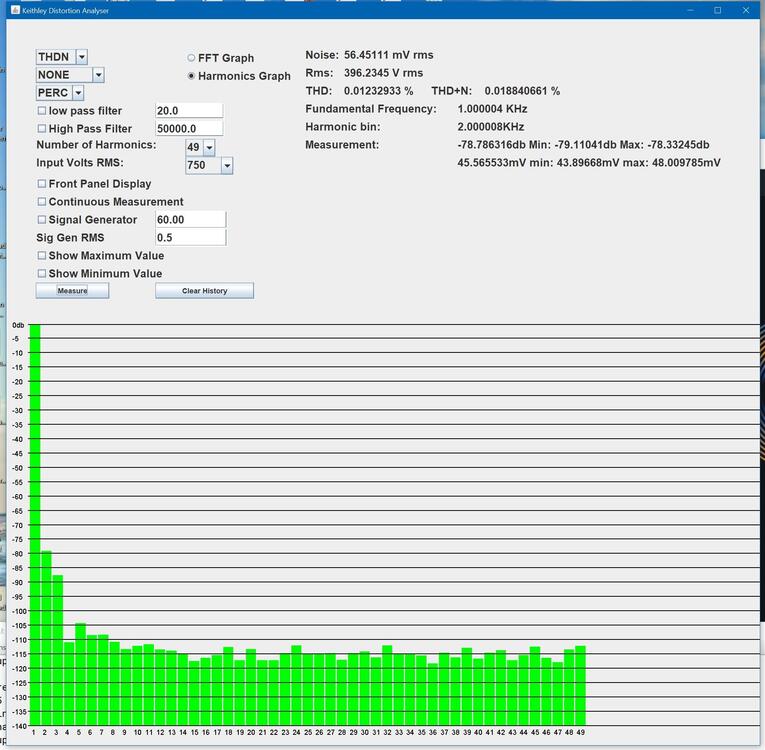
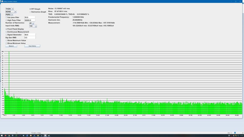
Here are some distortion figures and harmonic analysis up to 50Khz. Test setup groove tubes el34 matched, electro harmonix gold pin 6922 matched, 1Khz sine from a 192K 24bit rme soundcard spdif out to a v90 dac to the mini t2 inputs, measured on a keithley 2015thd. distortion graph is the average of 20 measurements. All other readings are not averaged: Distortion is less than 0.02% up to 500V rms output with second harmonic being the highest and a little bit of third above the noise floor. At just under 500V the 4th harmonic is above the noise floor, above 500V rms clipping starts and at 600V rms distorion is ~2.5% with the second harmonic at -36db relative to the 1khz signal level. On the right hand top side of each graph under the measurement section is the measurements for the 2nd harmonic in db and mVolts average, min and max over 20 measurements. Noise is the ac voltage not in a harminic bin (i.e. a bin which is an integer multiple of 1Khz). Analysis is with 749 bins going from 20hz to 50khz. A full fft with all bins is included for the 100Vrms output only at the bottom of the post. I wrote the software myself, its very much a rapid prototype kludgy mess but I hope to make it available to community members with keithley 2015 when the code is not so offensive. At the moment there is no guarantee that it will not open up a dimensional hole and make all your original NOS Japanese transistors disappear. FFT analysis 1Khz 100Vrms output. 20hz to 50khz


-
The 2sk389/2sj109 have unusual packages so the chances of fakes are probably quite low. For TO-220 its a different story. In the uk on ebay I have had fake 2sa1486 from littlediode, fake 2sa1968 from nikko, fake 2SJ79 from littlediode_components (same seller as littlediode). I strongly recommend if you are going to spend money on original Japanese transistors you buy both a dca75 transistor identifier and a DUOYI DY294 transistor breakdown voltage tester. If you put a fake into a circuit the consequences can be catastrophic and cause considerable damage not to mention a danger to your life. For example the fake 2SA1486 had around 200 volts LESS breakdown voltage then they should have had and the 2sj79 did not even have the correct pin out and would fail as a dead short at almost any voltage if wired up as 2sj79.... The other problem is that ebay only give you a few months to return purchases. I did not get the DUOYI DY294 tester until about 9 months after I purchased the transistors (I simply did not realise fakes where a thing. I purchased the dca first and it identified the 2sj79 pintout as not consistent with the spec sheet... I thought the dca75 was miss identifying. Later I got the DY294 after reading about fakes on the T2 build pages and found the dca75 was correct) . Although I contacted ebay explaining that the seller was selling fraudulent components AND presenting a clear safety risk ebay said they could do nothing.... I contacted paypal.. again they refused to do anything and the sellers are still selling the same fake parts. So now I test everything. Luckily I did not lose a lot of money but I don't want to think about what would have happened if I had built an original blue hawaii with those components.... The dca75 is also useful for troubleshooting if you have a component failure. I had a 10m90s die on a golden reference HV board which caused a chain of destruction in my blue hawaii. The dcs75 was very useful for quickly identifying bad transistors. The hawaii was back up and running the next day. Although the dca75 is not designed for in circuit testing, if you have one channel fail or you are super paranoid after completing a new build you can always compare test results with the other channel. (its not totally foolproof compared to desoldering the components and testing out of circuit) but it can save a lot of time. Obviously you don't want to use the DY294 in circuit because injecting high voltages into a circuit is not a good idea. One word of caution, the DY294 cant be used to breakdown test depletion mostfets since by their nature they are conducting by default and so register as having a very low breakdown voltage. The DY294 can also be used to match and test high voltage zeners which can be useful. The sockets on the DY294 are not that great, but its trivial to replace them with colour coded leads with test clips on the ends, this also allows you to test smd parts using sot23 adaptors etc.
-
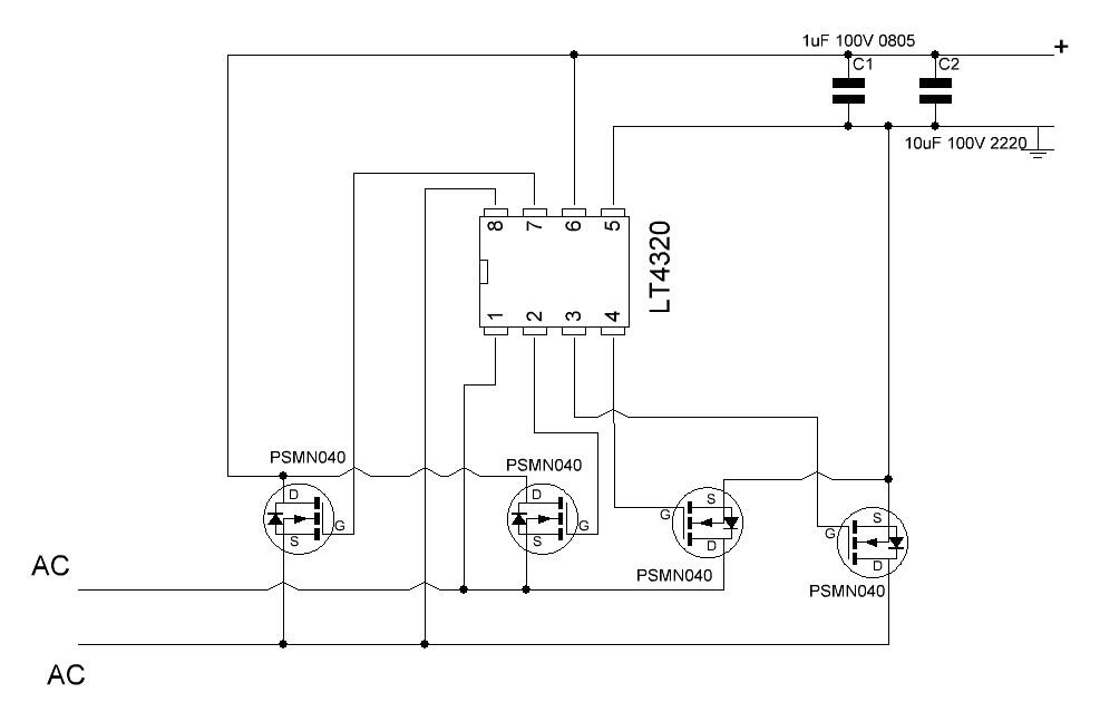
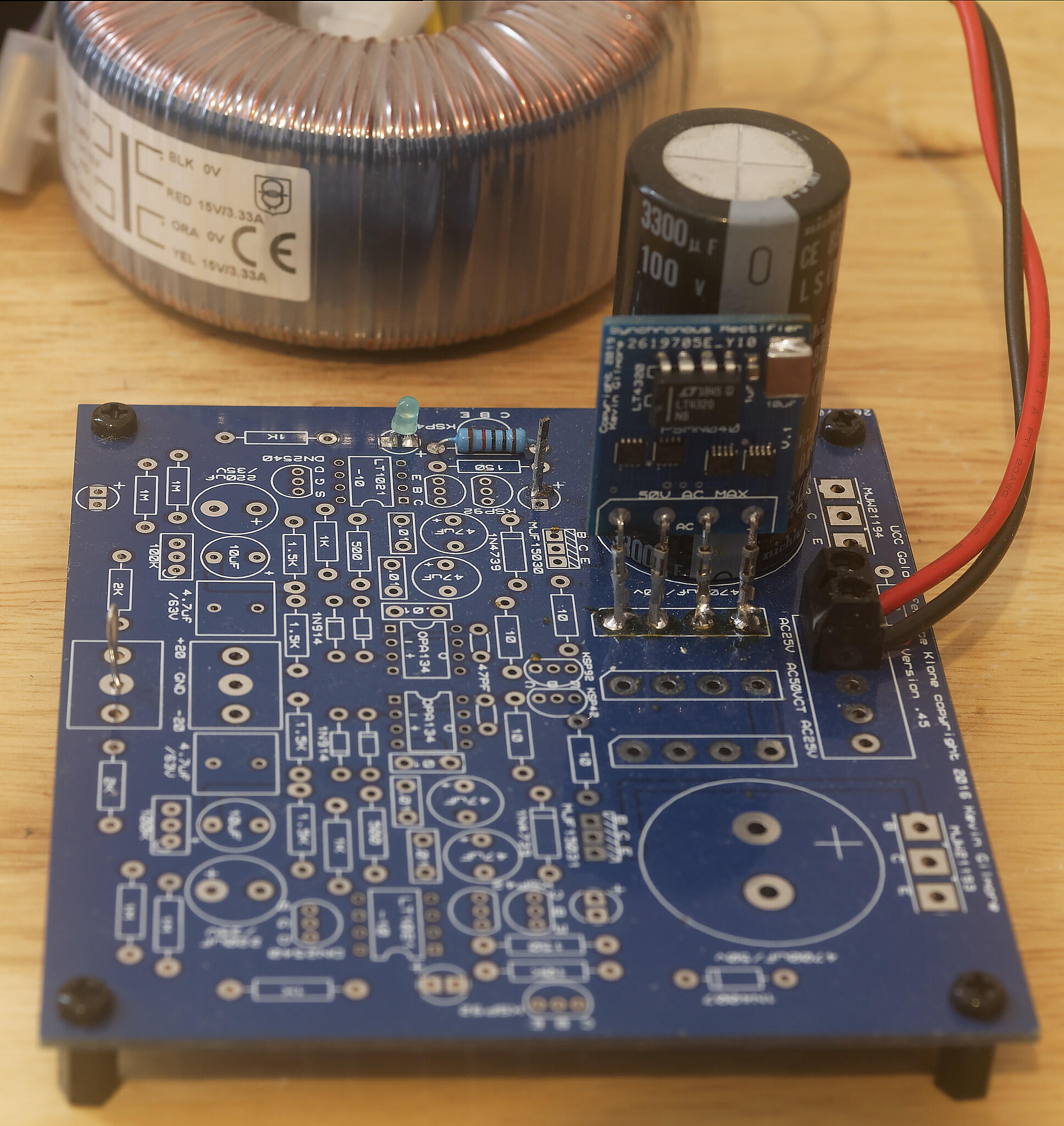
Synchronous rectifier load test: Temperature taken after 10 minutes of load. Test board same as my previous post with 1oz copper pcb. Voltages measured at input to test board and output of test board. Single rectifier tested no averaging. Ambient temp 22C. Temperatures rounded up to nearest whole degree C. open air no case. current draw | input voltage | output voltage |temperature of | temp of controller in A | to rectifier VAC | after 3300uF cap | hottest psmn040 | 3A 16.2 18.6VDC 107C 69C 2A 16.6 20.2VDC 61C 45C 1A 17 21.8VDC 34C 31C So it looks like 2A at fine. 3A is pushing it a bit hard at these voltages.
-
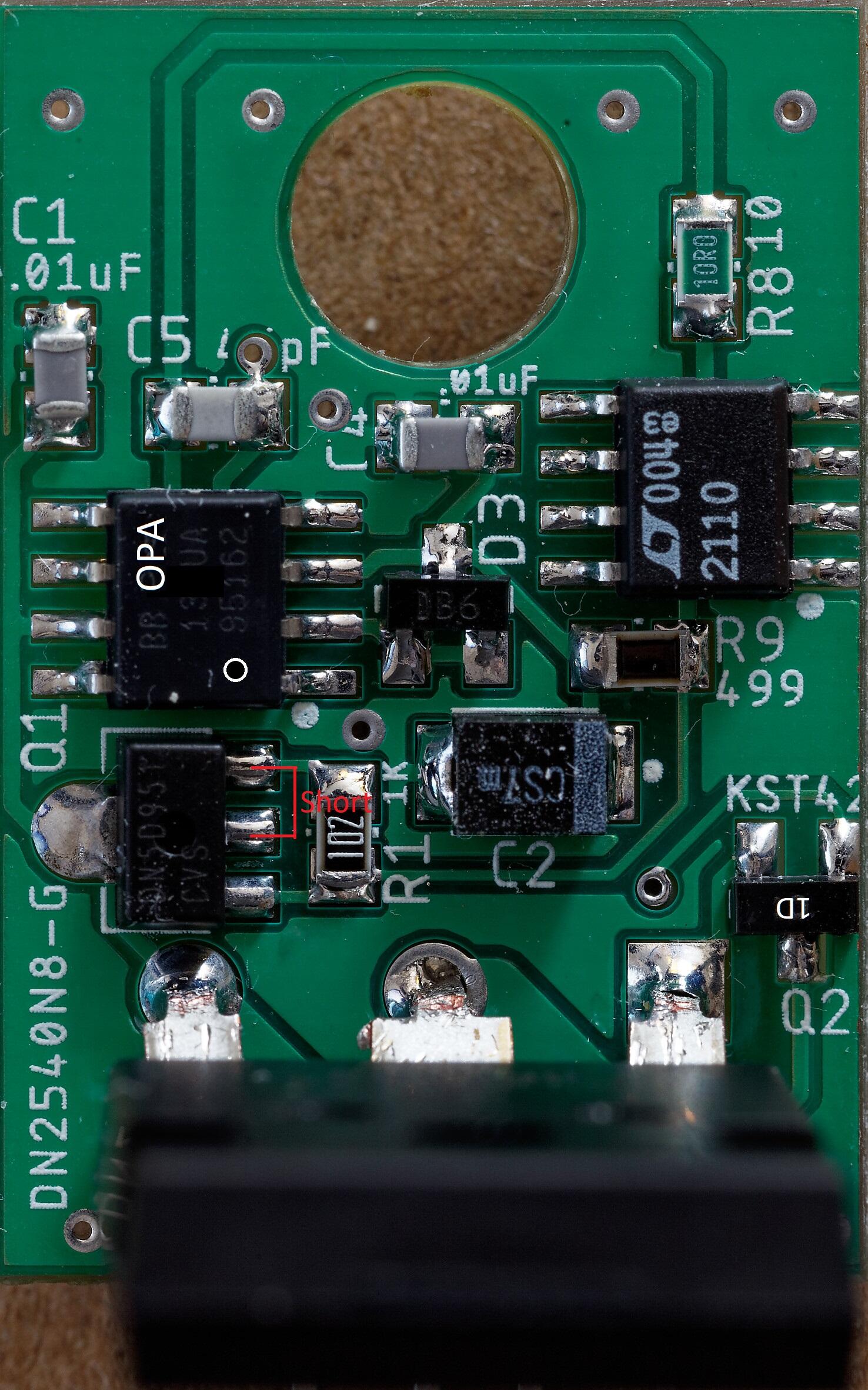
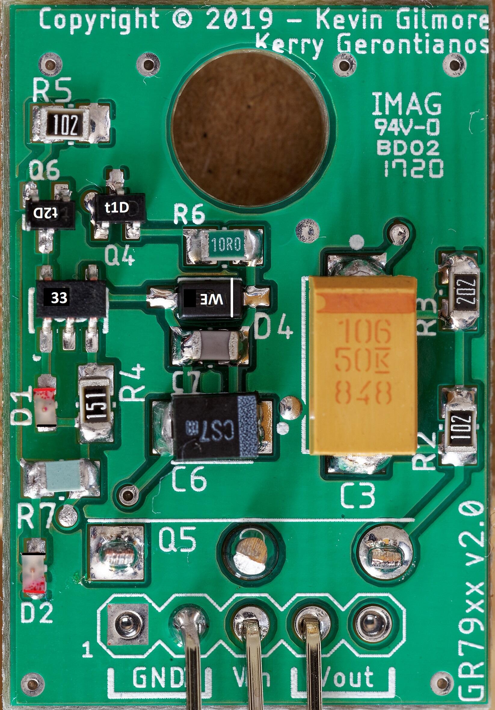
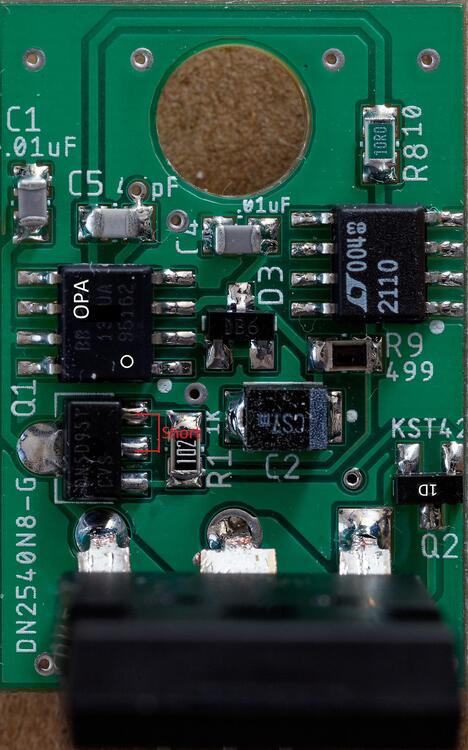
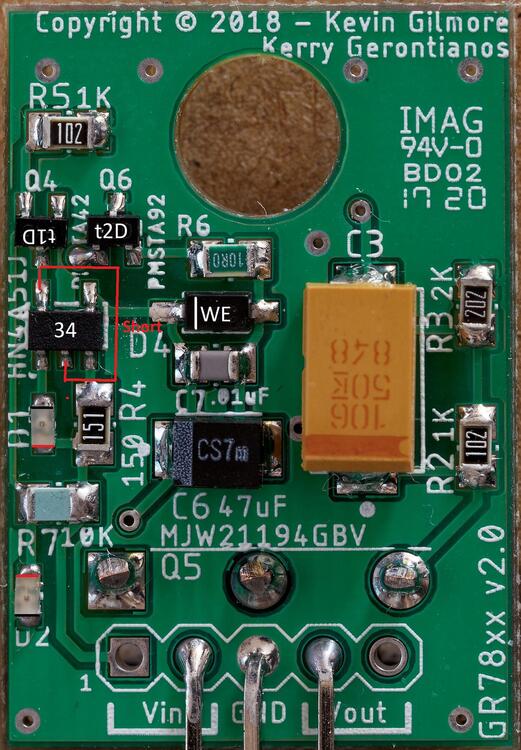
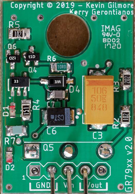
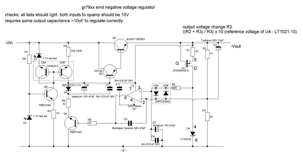
GR78xx build notes: Writing direction on the opamp and voltage reference match the writing direction on the pcb I suggest checking the led orientation with a multi-meter in diode test mode, finding out which way round the multi-meter leads need to be to make the diode light and then marking either the positive end of the led with a red pen or the negative with a black pen whilst holding the led with twisters - if you don't hold the led with twisters it has a nasty habit of sticking to the pen tip. The leds face opposite directions. Positive and negative ends are marked in the picture with red and black lines respectively. All transistors are shown with their case markings. Its a good idea to solder the leds in first and then check. D2 has the end closest to the Vin pins connected ground and so its easy to check its orientation is correct, the other led is opposite orientation. The DN2540 is a depletion device so if you measure resistance between pins, two of the pins will appear to be shorted - this is normal and shown on the picture. The tab is also electrically connected to the centre pin... The top left pin of the hn4a51j is also connected to the bottom middle pin on the ocb and will therefore also measure as a short. The pmsta devices have 3 digit case codes the first digit being the place of manufacture, the kst devices have two digit codes. Be aware Both the pmsta42 and kst42 have codes 1D but the pmsta42 has a t or other letter before the 1D for the manufacturing location. voltage ref should have 10V between pins 4 and 6 If you test the board by itself it must have capacitance connected to the output in excess of 20uF in order to regulate and not do strange things like increase the output voltage when the load increases. When setup for 15V output, input voltages bellow about 1.7V should result in very little current draw <1mA and no leds lit . At around 1.7V input D2 show glow dimly and increasing the input voltage should result in D2 glowing brighter, the current draw increasing and the output voltage increasing. When D2 is fully bright the current draw should be about 10mA. At about 17.5V input D1 should begin to light . Increasing the input voltage further will make D1 brighter and the current draw increase towards 10mA current the draw when the led is fully bright. At around 18.3V input the output should stabilise at around 15V and increasing the input voltage further should have no effect on the output voltage or current draw. The second 78xx I built required 0.2V more to regulate fully despite having a 8mV lower output. Load testing Expect approximately a 23mV decrease in output for each 100mA of load current drawn from the gr78xx. At 200mA the components on the board should be warm but easy to touch and leave your finger on. The MJW211 should also be a little warm. NOTE the metal tab of the MJW is live so don't short it to something. Voltage drop under load test, no heat-sinking, MJW211 close up against the pcb, 18.3V input. The drop in output voltage is the same using a 47uF output cap as 220uF. 100mA 23mV drop 200mA 46mV drop 300mA 69mV drop 400mA 93mV drop 500mA 116mV drop (note tab of mjw gets too hold to touch for more than a moment after a few minutes of this load. heat-sinking recommended) The second 78xx I built had voltage drops within 2mV of the first. The voltage drop under load is a bit more than a traditional 7815 to-220 voltage regulator under the same conditions. Removing the load results in the output voltage of the gr78xx going back to within 1mv of the original no load output almost instantly, even from the hot 500mA load. the voltage drop is fairly linear with load. Otuput voltage drift under constant load as the device heats up or cools down is very low. LED direction verification for gr78xx lower led D2 multimeter in diode check mode red probe on top of led black probe on bottom (as indicated in photo bellow) you should get about 0.89V drop led will not light. probes reversed meter should say OL upper led D1 multimeter in diode check mode black probe on top of led red probe on bottom (as indicated in photo bellow) you should get about 1.66V drop led will light. probes reversed meter should say OL 79xx build notes All polar caps, Zener and LEDs are in the opposite orientation to the 78xx, All resistors are in more or less the same positions and orientations as the 78xx, all transistors that are xx42xx become xx92xx and visa versa. NOTE in the BOM Q6 and Q4 appear to be the same on both the 78xx and 79xx however, on the silk screen the physical positions of Q4 and Q6 swapped in all other cases the transistors change in the BOM rather than the silkscreen designations moving. The opamp and LT voltage reference are in the same orientation as the 78xx. The HN4A51J becomes HN4C51J and the MJW211 changes from 94 to 93. All positions that hold a KST device continue to do so and the same is true for the PMSTA. Only the type of device swaps from NPN or PNP i.e. from kst42 to kst92 and visa versa or pmsta42 to pmsa92 and visa versa. The 79xx has similar load behaviour to the 78xx. LED direction verification for gr79xx lower led D2 multimeter in diode check mode red probe on bottom of led black probe on top (as indicated in photo bellow) you should get about 0.89V drop led will not light. probes reversed meter should say OL upper led D1 multimeter in diode check mode black probe on bottom of led red probe on top (as indicated in photo bellow) you should get about 1.66V drop led will light. probes reversed meter should say OL


-
Thank you for the quick reply You are absolutely right about the output capacitance. I recreated the golden ref through hole output cap setup of a 220uF and 4.7uF in parallel and that did the trick. D1 now slowly comes on when the input goes above 17.5v and behaves much more like the golden reference through hole and the gr78xx is now happily regulating at 15.014V with no load. At 18.26v the output is now 15.015v. 50mA load the output is down from 15.015v to 15.003V, 100mA output is 14.991V, 200mA output is 14.967V all with 18.26v input and no heatsinking. Switching off the 200mA load the output is straight back to 15.015V. Playing around a little more regulation works with just the 4.7uF film cap on one of the two boards but results in the other board increasing the output voltage with increasing load! putting back the 220uF caps makes the second board behave like the first with similar voltage drops with increasing current draw. The silkscreen for the gr78xx says hn4a51j which is a pnp part which is consistent with the through hole golden ref which uses 2x ksp92ta which is also a pnp transistor... now if i could get more voltage references I could build the gr79xx boards....
-
has anyone built a gr78xx and tested it yet? my gr78xx refuses to regulate. 😞 I just finished building 2 gr78xx. tested both for shorts and not connected components. each in turn to a DC power supply, with current limiting set to 50mA, nothing connected to the gr78xx output except a multimeter. Things started well, D2 just barely started to glow at 1.8V input to the gr78xx, as the input increased D2 glow increased... D1 suddenly started to glow at 16.3V input and the output voltage at this point was 15.088V. Current draw from the dc power supply was around 20mA, no bangs no surprises... but when I increased the input voltage more the ouput voltage just followed it. At 18.26 input the output was 17.073V.... I checked the voltage ref 10.005V between pins 4 and 6. No components feel overly hot. Both gr78xx have been ultrasonically cleaned. Both the gr78xx behave exactly the same way. On a DC load the output voltage drops with increasing current draw at 250mA the output is 14.58V BUT D1 and D2 remain lit with no change in brightness compared to no load on the output. any ideas what could be the problem?
-
I believe there is a small error in the BOM for the GR79xx. Q2 is stated as "PNP silicon kst42 or MMBTA92" but the kst42 is NPN I believe it should be a kst92, given in the golden reference through hole, the transistor at that position is a PNP AND the MMBTA92 is a PNP.
-
Thank you for the group buy, my boards arrived a few minutes ago.
-
the capon coated volume volume extender shaft is the fuse.... all my lt1021s from mouser have a 2 digit code at the top right of the chip (most have e3) running vertically downwards... so im sure those voltage refs are legit too. P.S. talking of fakes dont buy from little diode on ebay in the uk... I got 2 sets of 4 2sa1486 from him fake.. C to E breakdown voltage a massive 360V... specsheet 600V... and 10 2SJ79, on a peak dca75 transistor identifier it shows D and S are swapped compared to the spec sheet! I would not want to see what happens with that in a circuit... Breakdown voltage using the specsheet pinout 0V! breakdown voltage using the pinout the dca says <100V... spec sheet 200V... and the "best" one so far from nikkolec on ebay $200 of 2sa1968s. Peak dca75 detects them as npn but spec sheets says pnp! breakdown voltage is 190V not 900V guaranteed firework display if used.... sigh
-
-
I believe all the 6922s might be run off one winding since the heaters are ground referenced and the current draw is much less than the el34s but I have not tried it. As joamat says the el34s cant share a heater winding with the 6922s since the el34 heaters are -400V with respect to ground. I have not tried running both channels el34s from a single winding because a. thats a lot of current draw 6A ignoring switch on inrush and magnetic losses b like joamat I don't know if it would be safe to do so. c separate windings provides a bit more isolation if/when things go wrong. You might want to message Kevin Gilmore for his advice.... P.S. jose have you signed up to the please add screw terminals to the mini t2 amp boards request yet 👿
-
paid. good luck everyone with your builds
-
I have run the amp without the balance servo, just by carefully adjusting the trimmer, but the opto coupler is connected to the dc offset (i.e. make the average of the + and - audio signals 0v with respect to ground) not the balance servo (which makes the average of the + and - audio signals 0v with respect to each other only. also check the valves/tubes if you have a tester... I have found the 6922s to be a bit fragile and the el34s have -400V on their heaters so if the negative 560V rail has gone crazy there could be heater to cathode leakage... do you have a variac? I always bring my new builds up to full voltage slowly... My amp has two transformers one for the heaters and +-15v and one for the high voltages. I connected the low voltage transformer directly to the mains and only connected the hv transformer to the variac. What resistors did you use? I used vishay crcw1206 which are rated at 200v and crcw0805 for the 1/8w which are rated at 150v., they were the highest rated voltages I could find on mouser for 100ppm 1%... I have a dca75 from peak electronics, https://www.peakelec.co.uk/acatalog/dca75-dca-pro-semiconductor-analyser.html#SID=24 its been very useful for post mortem checking (if I de-solder a transistor I can compare the dca75 measurement with a spare transistor of the same type. I often find failed transistors simply show up as dual back to back diodes or dead shorts. Note the DCA does have trouble identifying 10m90s and similar). I have even found some fake transistors using it. Its not designed for in circuit testing, but it can be use in circuit for comparisons between transistors in the left and right amp boards. If you have not got a dca75 I highly recommend it. You can also get an adaptor for sot23 https://www.peakelec.co.uk/acatalog/pca23-peak-component-adapter-sot23.html and I found an adapter on ebay for sot23-6, https://www.ebay.co.uk/itm/SOT23-SOT23-6-SOT23-6L-IC-Testsockel-Programmieradapter-Einbrennsockel-F3I4/383314954496?hash=item593f5a0900:g:dWoAAOSwTYZd8frU so I can test dual smd transistors too. I also created a little op amp test circuit on a bread board, unity gain just so that I could power it and feed in a test signal and scope the output, I got a adaptor for 8 pin smd from ebay https://www.ebay.co.uk/itm/SMD-SO8-SOP8-SOIC8-DIP8-2-54mm-DIP8-Programmier-Adapter-SMD-Sockel-150mil/252912033731?hash=item3ae2bb5fc3:g:yKcAAOSwmE9b-JqP so I could also test smd opamps.... I love having lots of test jigs. Good luck with your troubleshooting and repairs.
-
For me its not about the bit rates or sample depth but the care and attention put into the recording/remastering process. Very few companies make dedicated recordings in each format, an exception is the label 2xHD which document the recording chain and use separate brand adc for the different formats, DSD vs PCM, and so you can expect to hear differences due to the different ADC as much as the different digital formats. I suspect most multi format releases are recorded and mastered in a single format at a single sample rate and then converted to the other formats. The conversion is not perfect and this is easy to demonstrate. If you take a very low frequency square wave and convert from 44K to 88K or go the other way the square wave is not preserved... conceptually you just remove half the samples or double each sample but in reality its a fast Fourier transform and digital filters (c.f. Izotope RX)... and FFT does not work well at low frequencies and neither do the digital filters.. I hear less differences between modern dacs than I do other components like speakers, cartridges etc. I will say the early dacs were terrible. I have spoken with one hifi designer who admitted that of all the audio technology dacs have probably improved the most in the last over the period late 80s-2010s. certainly I could not find a dac I could live with until the late 2000s and then it was super expensive, now I am happy with a V90 with a golden reference LV psu... A very cost effective combo which performs as least as well as my crazy expensive (even second hand) DCS elgar plus, even if the v90 does not have DSD support, input options etc. MQA is loss-full compression (it was original advertised as lossless but analysis has shown it is lossy) and has not really gained much traction, its potentially full of digital rights management and designed for surround sound. (https://audiophilereview.com/cd-dac-digital/mqa-the-facts-versus-the-fiction.html)... now its advertised as less lossy than mp3 and the DRM is not currently switched on... MQA playback requires licenses and so its unlikely to appear in open source playback software and even Jriver media centre has no plans to add it... I guess the license costs are too high. Software like Jriver media centre can convert DSD to standard PCM and this is how I listen to DSD. The advantage of DSD is that the ADC converter is simpler and has less filtering. The disadvantage is that the playback requires more filtering (DSD generates a lot of high frequency noise) and its not easy to edit DSD... almost all editing is done by converting DXD 384K PCM and then converting back to DSD this process is supposed to incur no losses... There is very little music available in DSD format and even less thats only available in DSD... My philosophy is get a modern dac, make the psu good and use the saved money on a better amplifier/speaker/headphone where there are still large performance differences... and don't forget to clean the connectors with deoxit or similar periodically. My mii T2 was recently sounding off colour, a bit lifeless and lacking detail in the mids and just sort of tried. I cleaned up the rcas and its back to singing again...The connectors on my van den hul first seem to love to oxidise a lot and rather quickly too... the cotton bud came out almost black from a single rca connector... regards and happy listening James
-
The subcontracting is everywhere. For example the courier dpd in the uk, deliveries are by DPD and if you have a company account with them you can send things. If you don't have a company account you can use DPD online or DPD local... all three are separate companies plus DPD online has no telephone support, not even an support email address. DPD local has telephone support as does DPD. None of the support of any of the three companies has access to the records or support of any of the others and you effectively have separate accounts with each one... what a mess. The DPD website does not mention this but as soon as things go wrong you find out the hard way... especially if you sent something using DPD online and expect to talk to someone on the phone rather than by web text chat to someone in India who has no clue.... Many Amazon deliveries in the uk done by "amazon logistics" AKA yodel. Judging by the internet and my personal experience Yodel is probably the worst delivery company in the uk... I ordered something before corona virus lock down, delivery to my university address. By the time it arrived the university was closed due to lockdown. Yodel did not contact me to ask for a new delivery address or inform me of any problem. Fortunately I was pro active, when I looked at the tracking it said to go to a web page to change the delivery address... when I tried the page said you don't have permission to change the delivery address!. So I tried to contact customer support... Telephone support... closed because of corona virus. online support.. busy waiting time 5 days.... when I finally got through the support person 5 days later they where not sure if they could change a delivery address... 10 minutes waiting their line manager approved the change. I said my home address and they said no that address is wrong and for that postcode Yodels system says "N 40 london" I said thats an impossible address its not even in the correct format. I was informed it was the only address change they could make or send it back to the sender. I asked if they could hold it and I get the sender to change the address? NO the sender can only change the address once its sent back to them.... long story short 2 months later I am still waiting for delivery...
-
I built two mini t2s, I always build in pairs or they get lonely... there is a bit or board flex when inserting or removing valves, (the ptfe sockets I have grip very tightly). No issues I can see with 1.6mm and 1oz, that's what I have used for all my builds, (4 dual output GRHV boards, 2 single output GRHV boards, 7 GRLV boards, 12 synchronous rectifiers, 4 diamond buffers, 4 blue hawaii amp boards, 4 alpha centauri amp boards and 2 alpha centauri psu boards)..
-
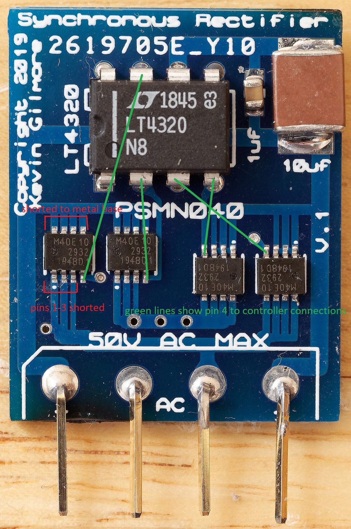
I have had no trouble using the zip with jlcpcb in china, I have sync rectifiers in my grlv in my blue hawaiis, mini t2s, psus I made for my dacs and a preamp I made,. Please be aware the sync rectifier will not work with centre tapped windings . so if you are making a grLV you need two independent windings and two sync rectifiers,. you cant use the GRLV option for centre tap and one rectifier I have tested it myself the sync rect does not work in this configuration but a normal diode rectifier does. The pin pitch is rather small and you need to check very carefully for shorts between pins 3 and 4, (pins 1-3 are internally connected together) and between the metal base and pins 1-4. I created a small test rig for the sync rect, I used a spare grlv board, put a female header where the rectifier solders in, added a largish value smoothing cap and bring the sync rectifier under test up slowly using a current limited dc supply and when I believe its ok, I swap the polarity of the dc supply and repeat so all 4 psmn040 are tested. I then use a 15v transformer and bring the sync rectifier up slowly on a variac. So far I have had one psmn040 smoke, I think I had a soldering short between the metal base and pins 1 or 2 or 3 or 4. Fortunately the expensive lt4320 survived without issue and I was able to reuse it. the test rig also includes wire loops for attaching a multi meter, scope and electronic dc load. I populated the diode next to the cap and one led partly to help drain the cap and to give a visual indication the board is live. Once the board has passed variac tests, I test switch on with no variac so the cap will cause a reasonable inrush, then I test with an electronic DC load up to 2A. .