jamesmking
High Rollers
-
Joined
-
Last visited
Everything posted by jamesmking
-
water cooled data centre means you can overclock the cpu(s) more....
-
fantastic. I was about to lose all hope. thank you to everyone involved in getting head-case back online
-
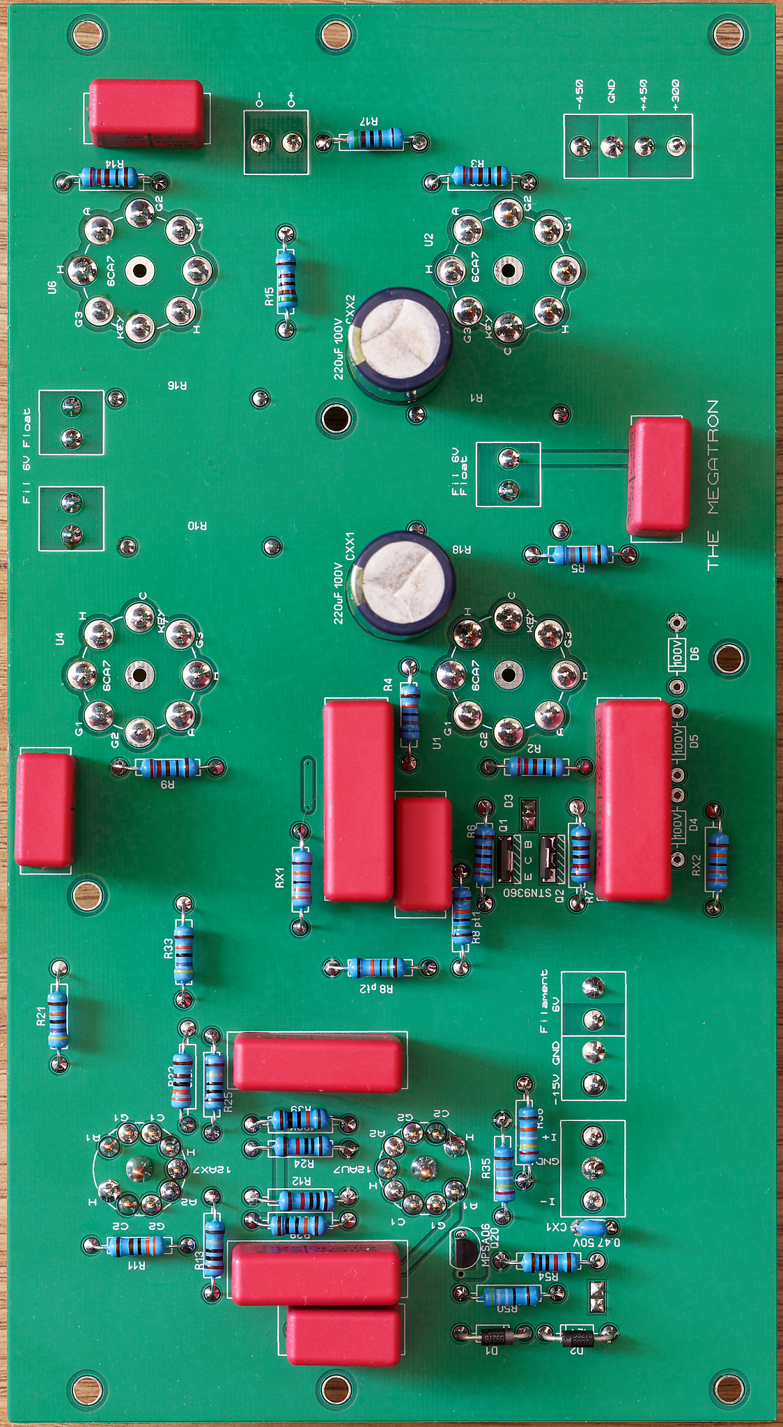
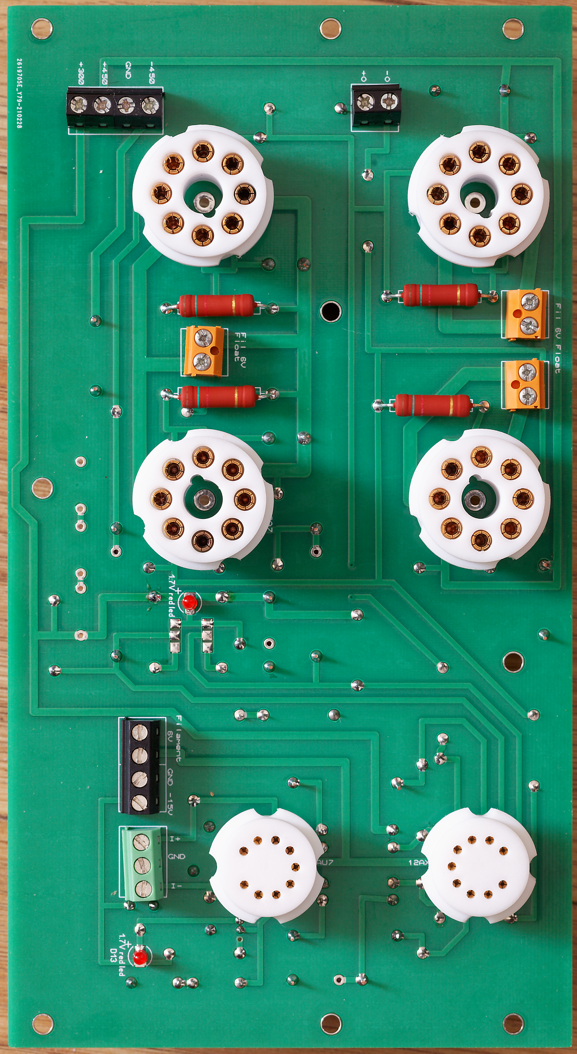
My megaslow build. Thank you JoaMat for supplying the 3 mosfets I needed for the golden reference psu. The megatron is workingish. This build was a little perplexing. I used groove tube 12ax7, electroharmonix 12au7 (gold pin) and groove tube el34s. I implemented the 12ax7 increased current modification form the outset. I found that I could only get about 220Vrms output before clipping. The clipping was not symmetrical and it was the bottom of the wave on the +O that was clipping only. I started to probe with a scope and found that the voltage drop at the 330K anode resistors on the 12ax7 was only about 19V on the +O side and about 35V on the -O side. Everything else looked fine. I scoped the output of the 12au7 when the amp was fine - no clipping when the output of the amp clipped. I checked all the psu voltages - no problems. It was the output of the 12ax7 was asymmetrically clipping. I took the valves out and measured them and the 12ax7 was only managing about 0.5mA output on one plate and about 0.8mA on the other. The avo manual said I should be expecting about 1.2mA. I was not sure if the amp had damaged the valve or if the valve was weak. So I checked the amp and removed the extra current modification and tried with a stronger 12ax7. Now both the +O and -O clip at approximately the same point but the clipping is still asymmetrical. I'm getting about 35V to 40V across the 330K anode resistors on the 12ax7. The bottom of both outputs clips before the top, and I am getting about 440Vrms output before clipping. I got in an email conversation with watford valves and the proprietor said that almost all new production 12ax7s are only capable of about 0.8mA and that only new old stock could do 1.2mA. So the high current mod might not be an option if you are running new production 12ax7s. I did some frequency response measurements and found the -3db point was only at about 23-24Khz... which seems rather low. Could someone tell me what output voltage rms they are getting before clipping and the -3db point for verification. thanks in advance James

-
it seems like at the moment the only thing in stock is out of stock notices.... 😞 check the height of the 1000uF cap... at 105mm tall its a beast which will not fit into a 2u case. (around 65mm depending upon the height of the standoffs for the pcb is about as tall as you can go for a 2U (80mm tall case)... are you going 120mm tall 3U case? the issues with very large capacitance input caps is that they will create a very large inrush current on switch on so you may need a larger value fuse than you would otherwise. Also the larger the cap the more diode switching noise it will cause because the caps will pull more current for shorter periods of time from the diode bridge rectifier. For the output cap some psu can become unstable if the output cap has a too high (or too low) capacitance. You may want to send a private message to kevin gilmore - the designer of the golden reference psu to get his input. Personally I use 470uF most of the time on the golden reference because I could not find any 680uF caps that would fit into the 2U cases I use.
-
if you are referring to the high voltage lines on a diy t2 - those psus use two 450V caps in series for double the voltage rating of one cap at the cost of halving the capacitance (except for rails bellow 300VDC output). The golden reference does not use series capacitors like this. the golden reference uses a single input and output cap per rail. So the each cap has to withstand the full voltage by itself. if the output is 400V then 450V is ok for the output cap giving you 10% or so margin. the input cap will need to have a higher rating than this because all regulated power supplies require more input voltage than they provide output voltage so they can maintain regulation. I think, if I remember correctly, the golden reference is about 330VAC input for 400VDC output. 330VAC once rectified through the diode bridge will give 330* squareroot(2) ~ 466Vpeak. Plus main voltage can vary, plus transformers can vary so to be safe you would want at least a 500V input cap. You may be able to get away with a lower input VAC if the golden reference can maintain regulation and your line voltage does not sag. Also consider that the higher the current draw the lower the output of a transformer and visa versa. So if you over spec your transformers current capacity the output voltages can be higher than you expect...
-
-
I did some experimentation and found that low airflow and fairly high air temp worked best for me. I have a quick 861dw hot air station. I set the airflow to 5 out of 120 and set to 360C (the temperature will depend on your solder paste melting point). I hold the hot air nozzle with one hand and with the other I use tweezers to keep the smd part in place. If you do not hold the part in place almost any airflow will send components into low earth orbit. The tweezers I use are curved on the end which makes it easier to place components, keep your hands away from the heat and easier to see what's going on.

-
-
opa134pa is exactly what i am using and is fine the LT1021DCN8-10#PBF is about half the price of the version of the reference your are proposing. The output accuracy is a function of the accuracy of the LT AND the divider network (which sets the output voltage) by taking the output and dividing it down to a nominal 10V. This is fed to the opamp which acts as a comparator between this and the LT. Unless you are going to use 0.1% or better tolerance hand picked resistors for the divider network there is not much point in spending $$$ on a very accurate version of the reference when the divider resistors are 1% and will drown out any extra accuracy a more expensive version of the LT will provide.... If you want high accuracy and don't want to spend $$$ you can always hand measure and match the resistors to get a more accurate output voltage (if you need that level of accuracy).
-
well my amp boards for the megaslow build finally arrived today. I have decided to use a golden reference HV psu for the +-450V and a second golden reference hv for the +300V. The psus are finished other than I don't have and cant source the pass mosfets.... *sigh* One question. since I will be using a 300V psu do I need to populate the 3*100V series zener string connected from the 300V line down to ground? I assume the zener string is there to stop the 300V line rising above 300V with respect to ground if the 300V line is derived from the +450V line via a dropper resistor.. or is there another reason why the string is there?
-
The pcb files are in zips with the contents in a format called gerber which can be uploaded to a pcb manufacturer like jlcpcb. The gebers contain all the necessary information for the creating the copper tracks, drilling of holes, silkscreen printing etc. Often there are minimum order sizes of around 5 of each type of board so often people have spares... There are no step by step instructions. There is an assumption that you can read a schematic, are prepared to read through some very lengthy forum threads and do basic drilling for mounting boards to heatsinks etc. the information is a bit spread-out. In general you need: BOM - bill of materials to get the right value and size components. Downloads from the appropriate forum thread for your build (and possibly two threads - the second thread being for the power supply) schematics - for troubleshooting etc in the forum threads and or download from https://drive.google.com/drive/folders/0B7egryukiT7_TFlEQlBRejdVdDQ the gerber files for getting the pcbs made in the forum threads or download from https://drive.google.com/drive/folders/0B_iJFfZStuVhSE5nOHBVdTByR1k the specifications for the transformers. in the forum threads. advice. in the forum threads and ask in the threads. in general the markings on the pcbs takes precedence over the schematic or bill of materials (unless the pcb has a silkscreen error). Some amps have more information than others - the threads grow organically over time depending upon popularity, etc. In general support is available for everything on a voluntary basis. You post questions on the appropriate thread hope for someone to answer. There are some very knowledgeable and helpful people active in the forum for example Kevin Gilmore, Kerry, JoaMat. Often the people who created the design will answer questions in the forum posts or people who have actually built one or even modified one. Unless you have lots of money/luck/ or existing stocks of obsolete components obtained from known good sources, I would stay away from any design which requires no longer manufactured transistors. There are many fakes floating around which can and will fail catastrophically on first switch on and non fakes are rare and there are few trusted sources willing to sell to non friends. I would advise reading the forum threads from start to finish and making notes, that way you can see the different versions/modifications emerge, see issues with certain components for example in the DIY T2 thread the voltages are high enough that some makes of resistor sparked and the insulation broke down.... Look at what people did that worked or did not work and learn from their experience. Finally if you can, give as well as receive. Post what works for you, post pictures, post updated bills of materials etc.
-
I also have the peak dca75 and several adapters. It can't test at high voltages or currents but its insanely useful for identifying transistor pinoutsand the type of transistor. I have used it several times to identify bad/failed transistors making troubleshooting much easier. The windows software also provides curve tracing which is useful for matching small signal transistors and leds.
-
Digital-First Retail Limited owns Maplin. the company did not exist prior to 29 June 2018... and has changed the location of its registered office no less than 4 times since then... The original director of the company resigned 6 oct 2020. The accounts only show 2 employees ... so im guessing its a shell company. The accounts is interesting section 476 means no requirement for external audit of accounts, section 477 companies act 2006 exemption from audit and exemption from publishing a full statement.... so the entire financial statement is simply one line current assets, one line creditors amount due and one line net assets. current director is director of 1 other company and previous director of another - all from the same address.
-
quick heads up KSA1220AYS transistors are now END OF LIFE https://www.mouser.co.uk/ProductDetail/ON-Semiconductor-Fairchild/KSA1220AYS/?qs=ljbEvF4DwOOJTVoo5AYsWQ%3D%3D 😞 mouser is currently out of stock radio spares has stock farnell is out digikey is out
-
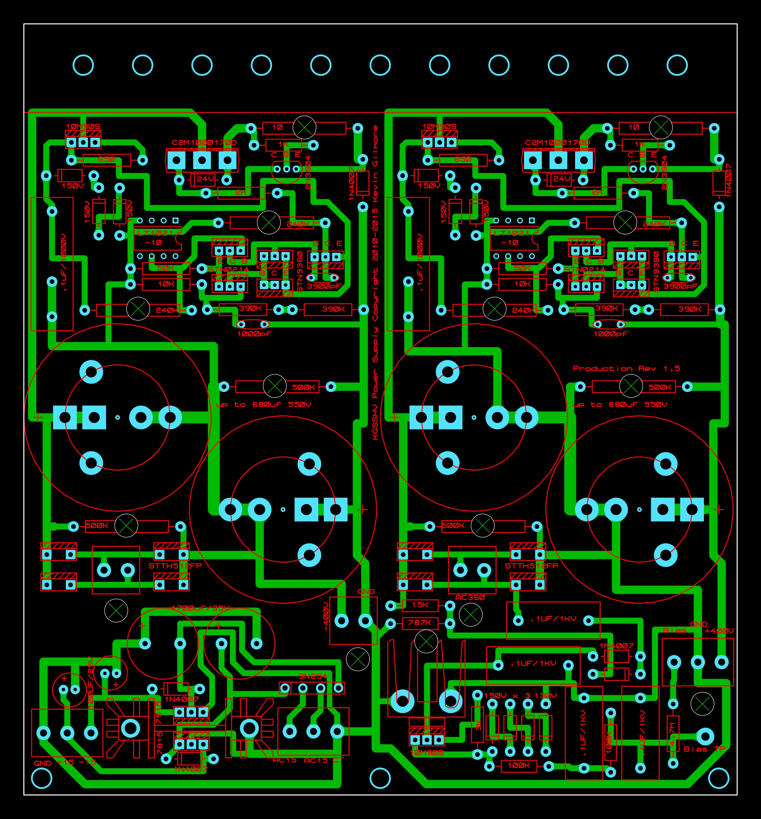
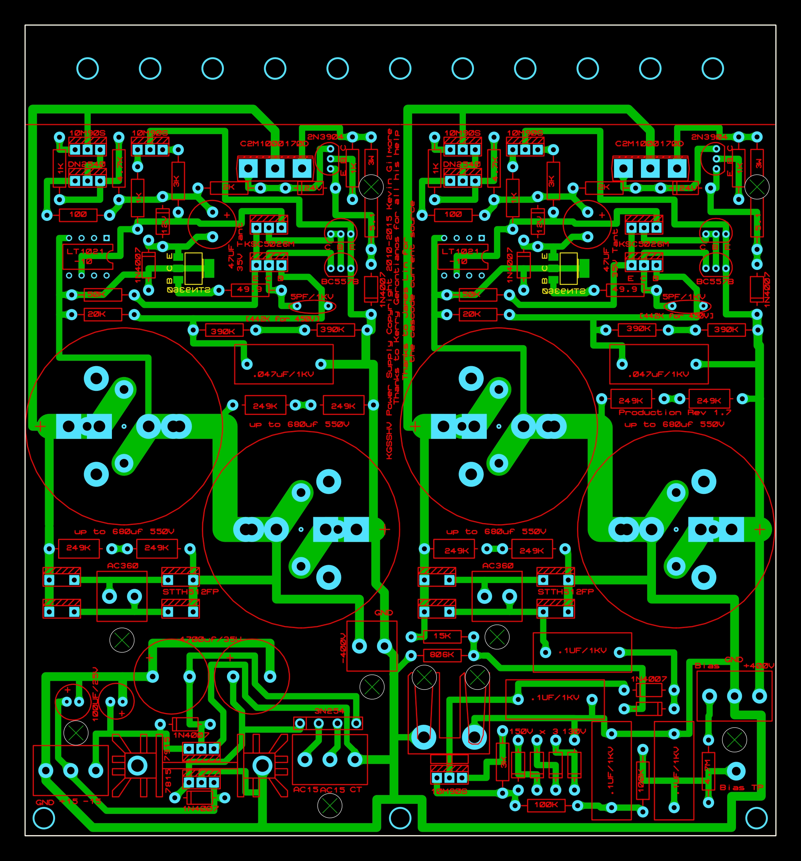
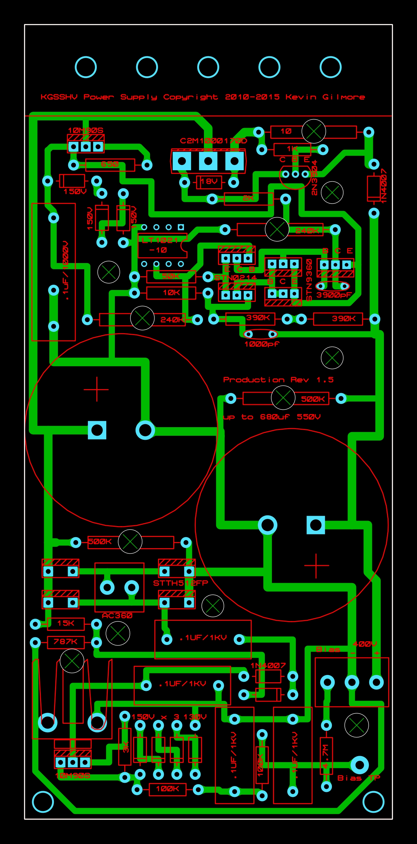
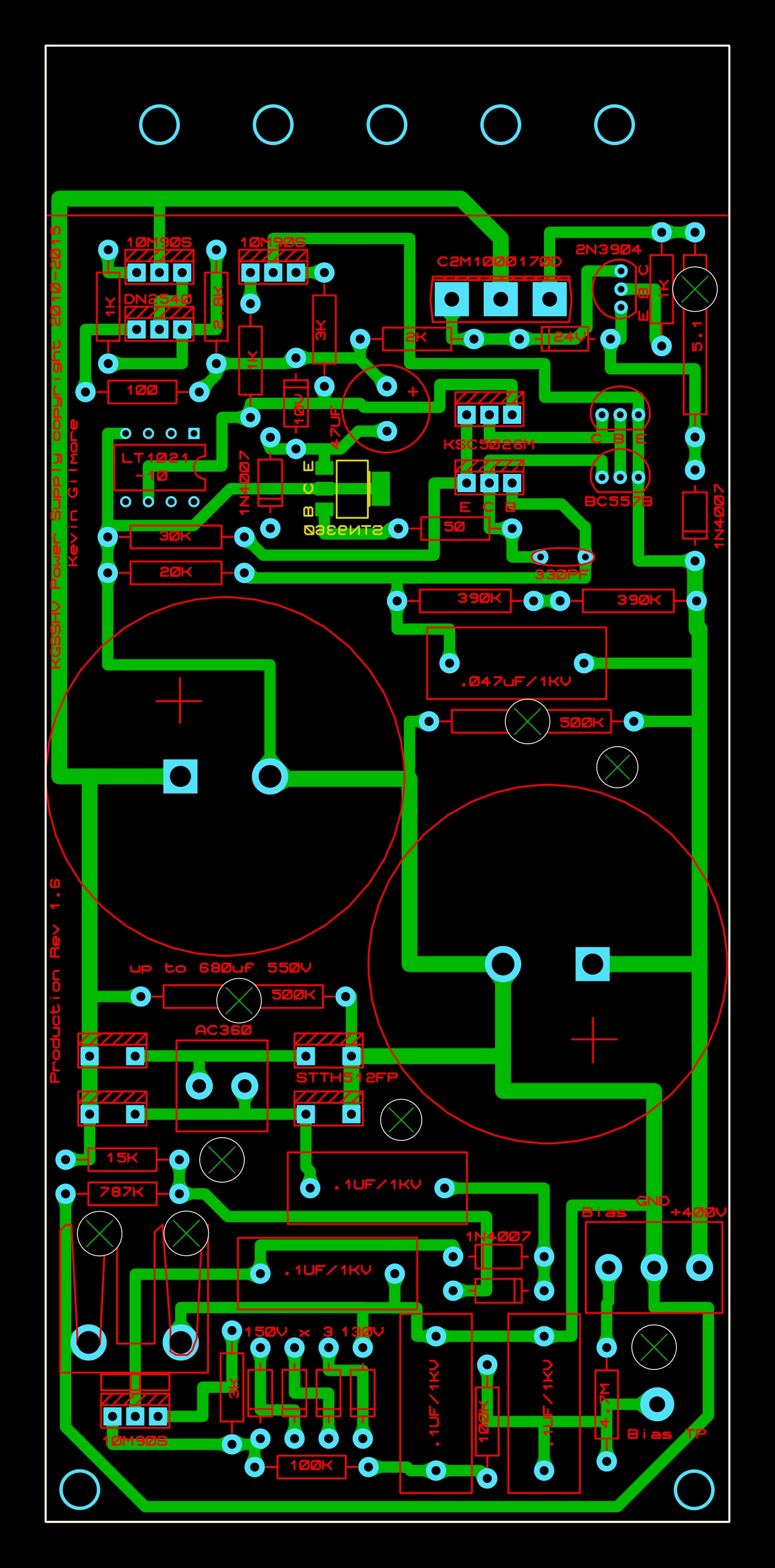
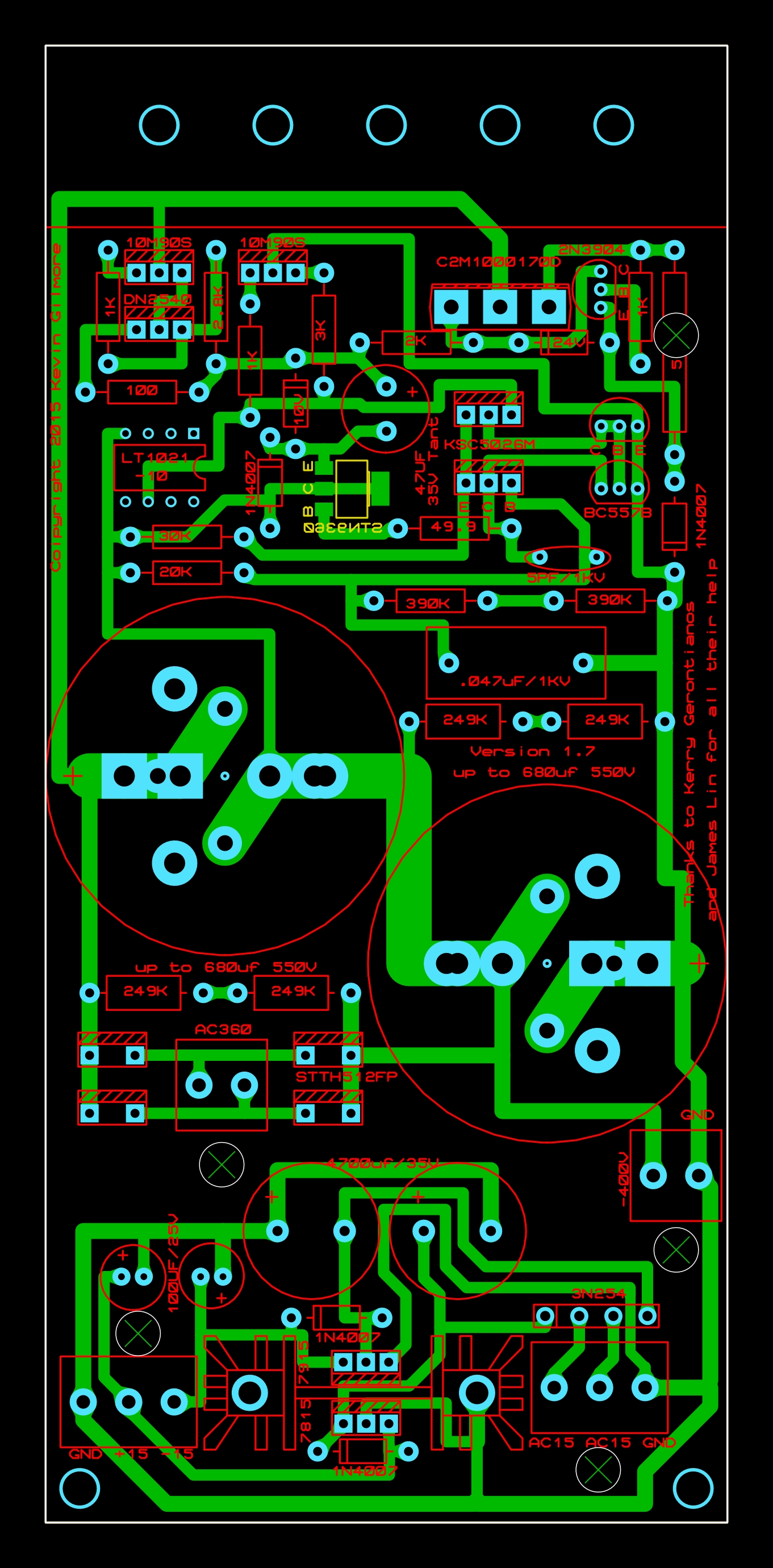
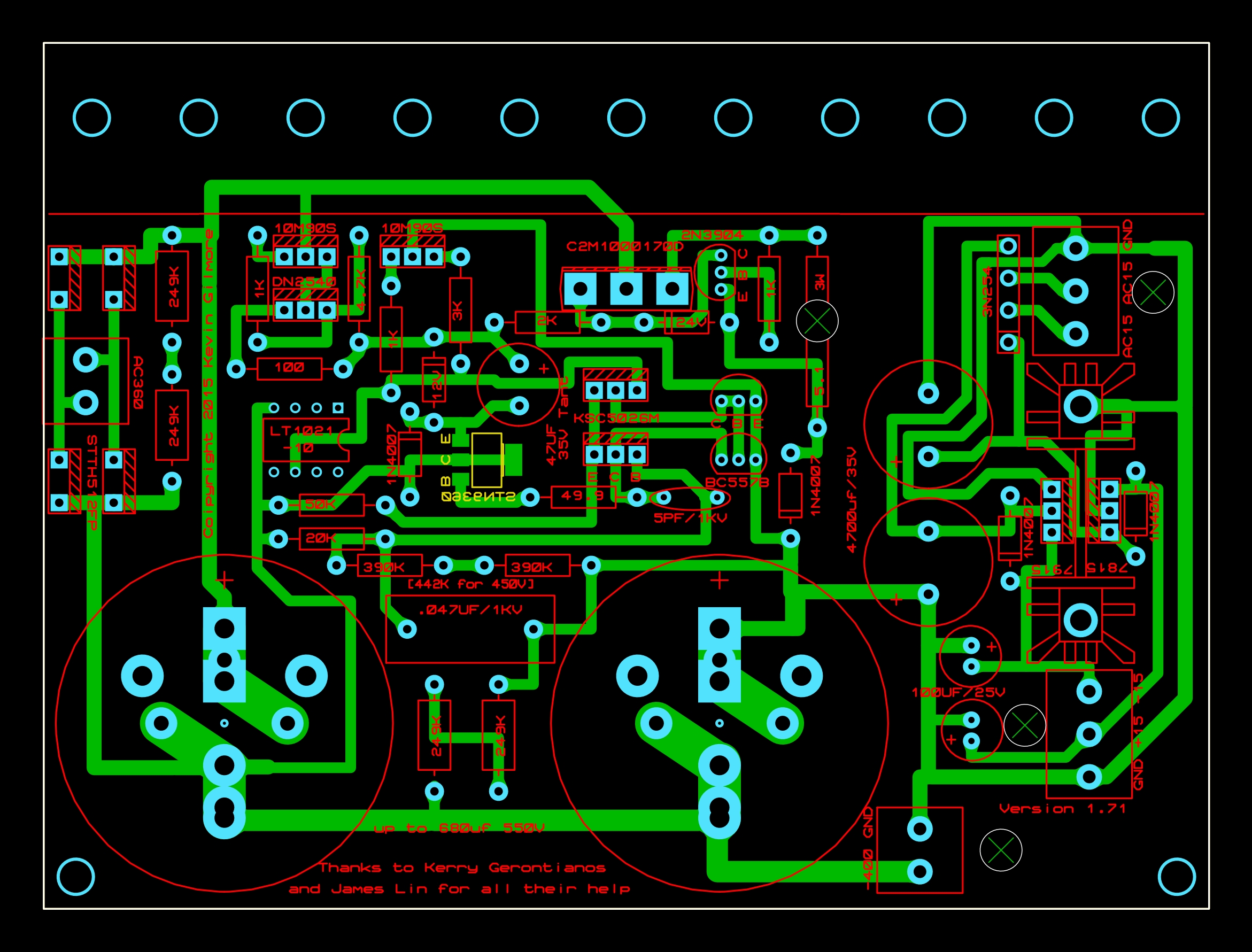
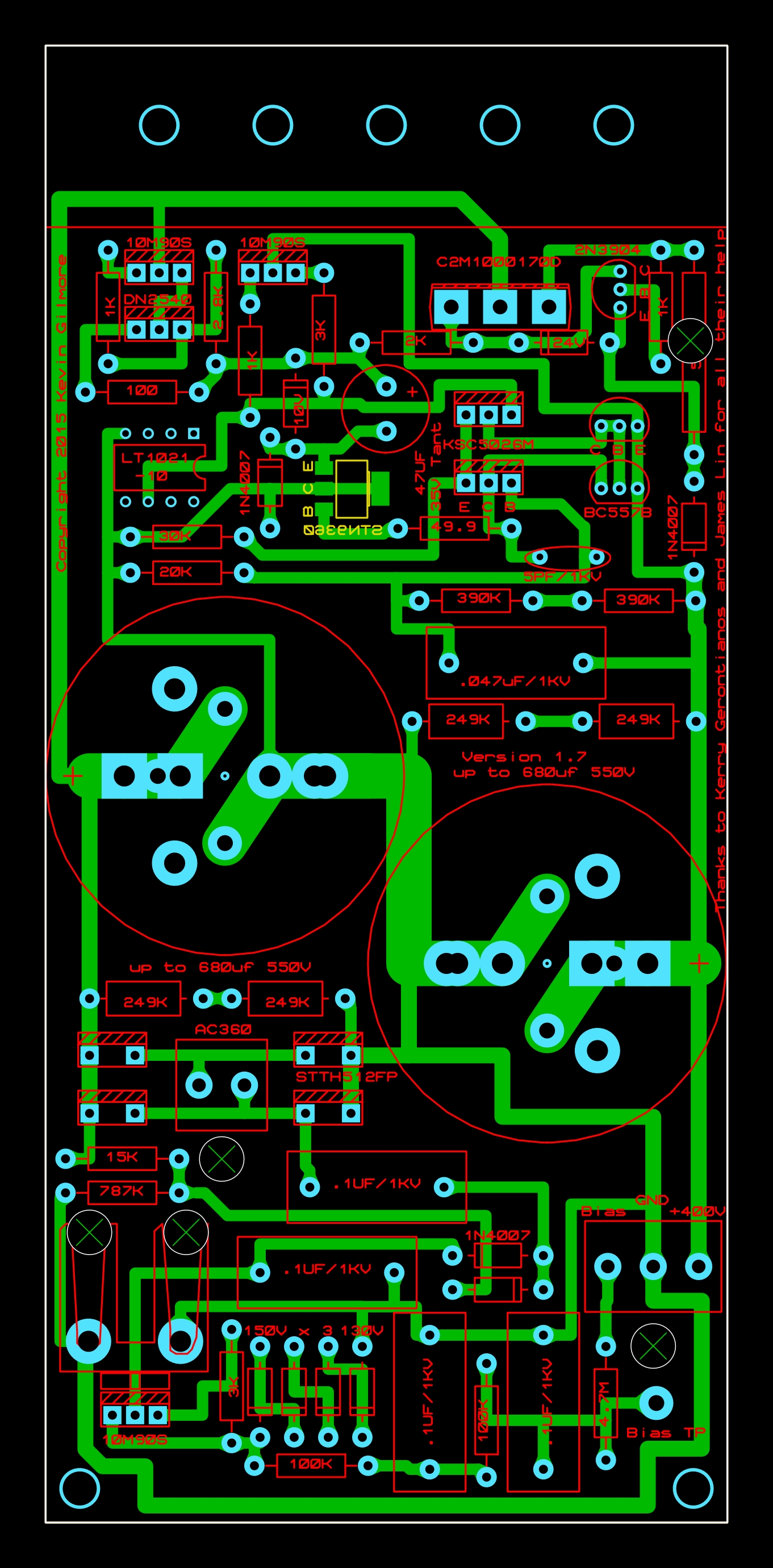
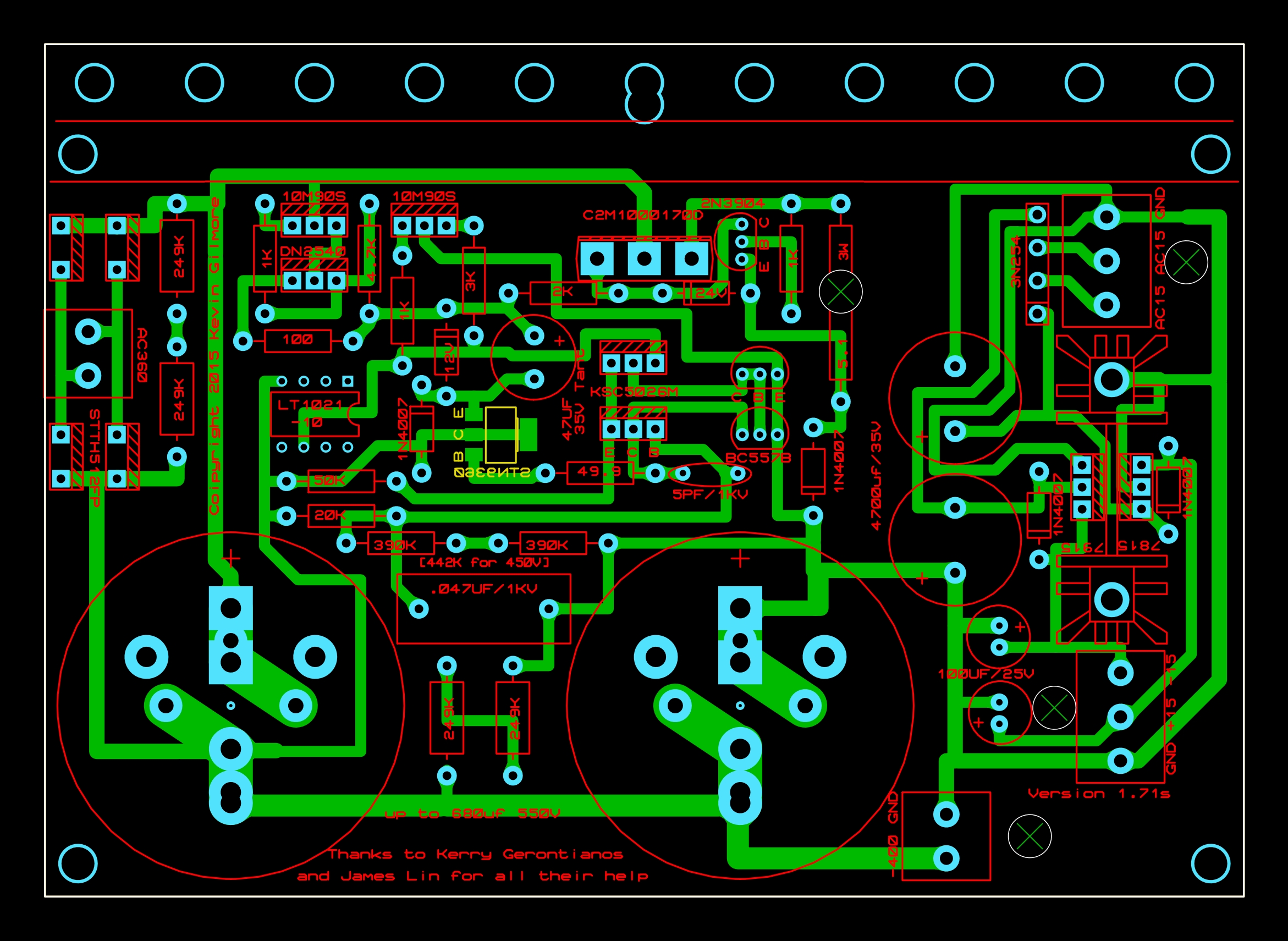
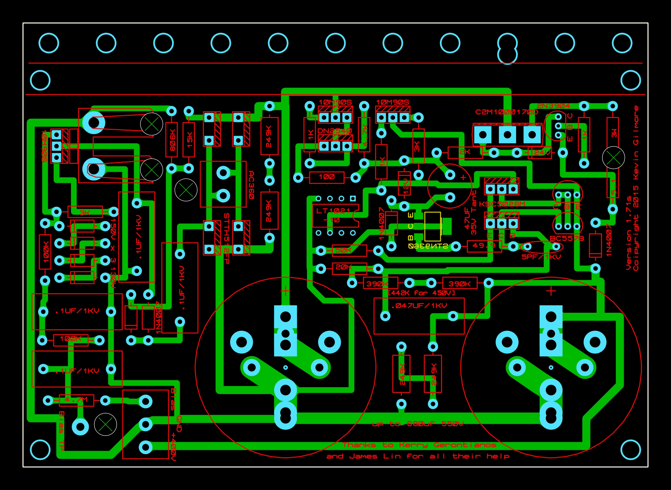
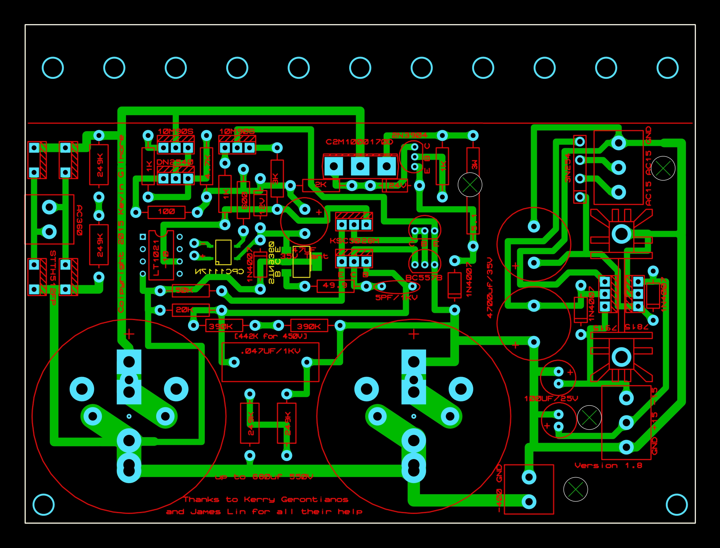
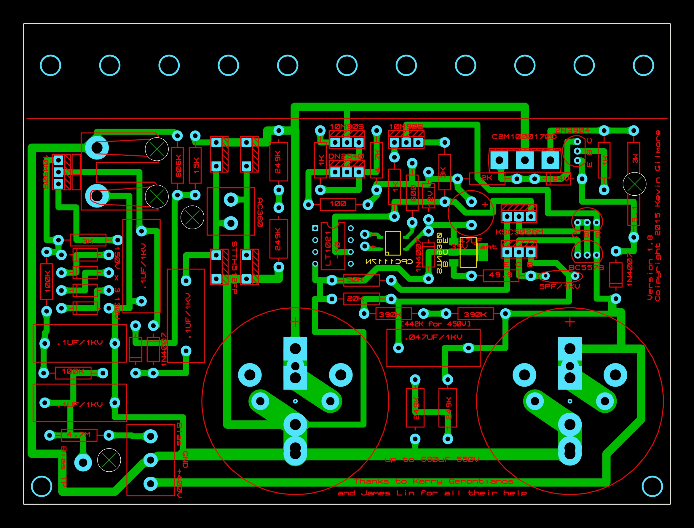
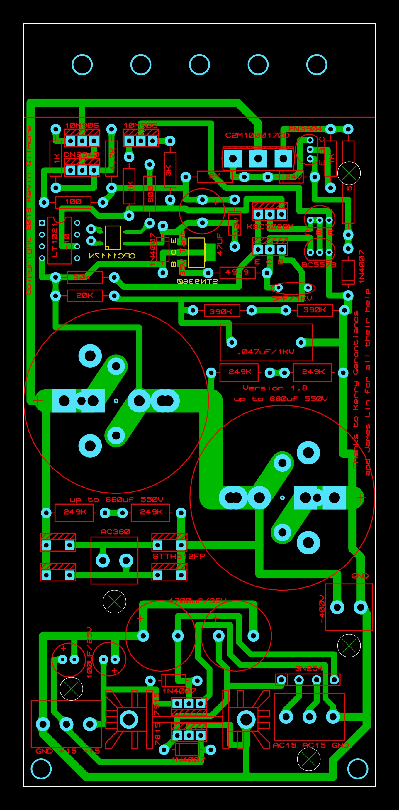
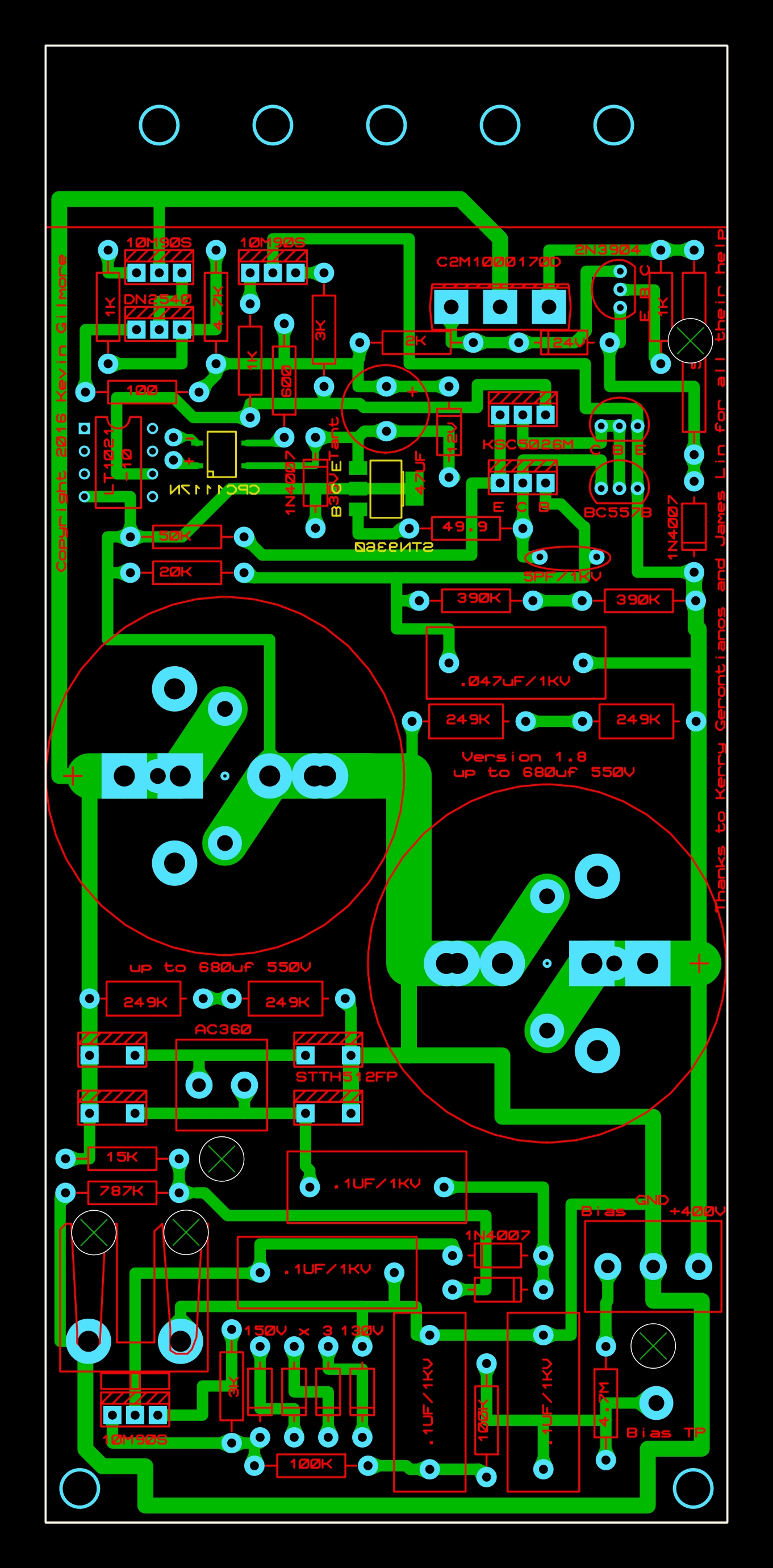
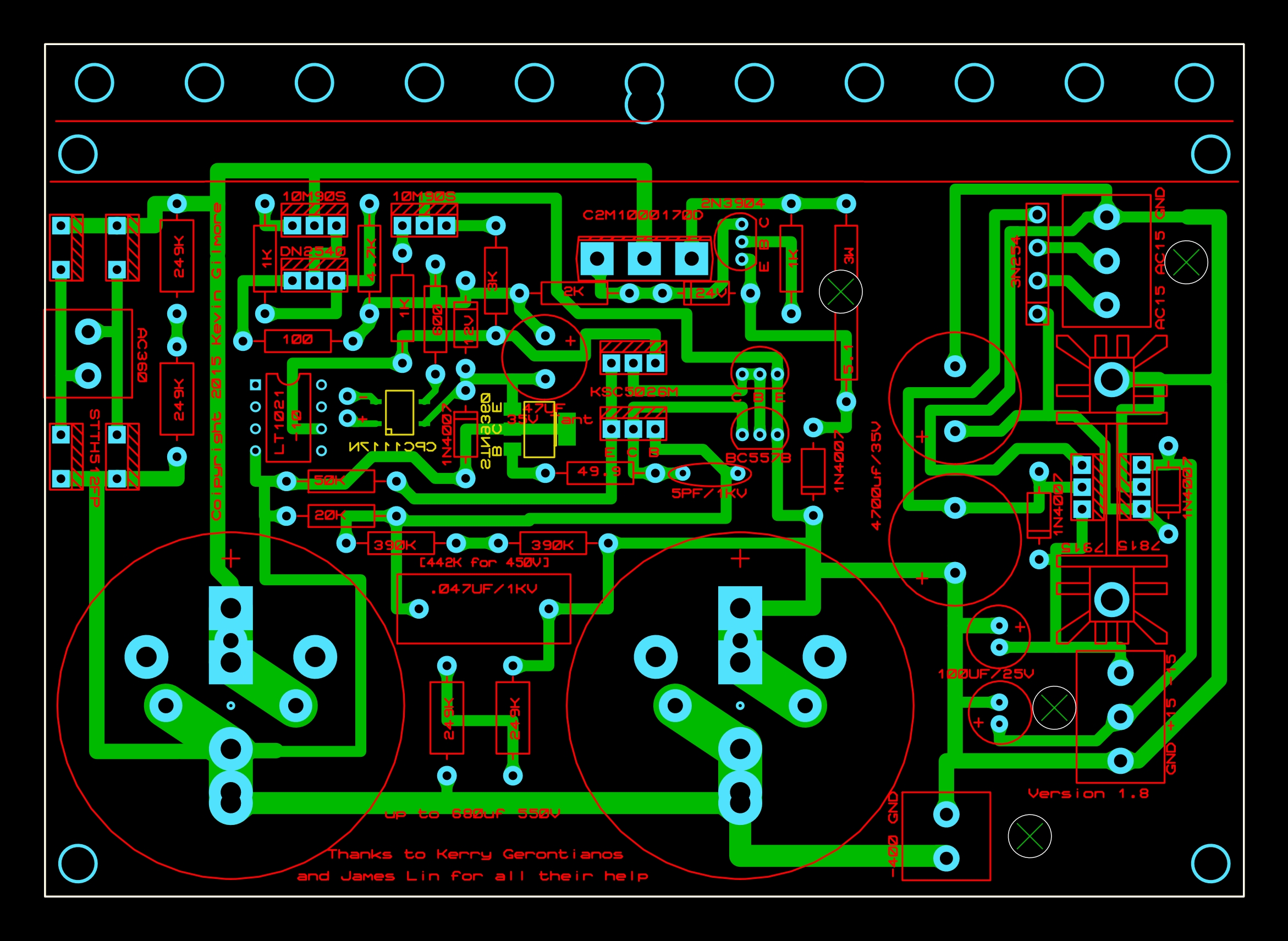
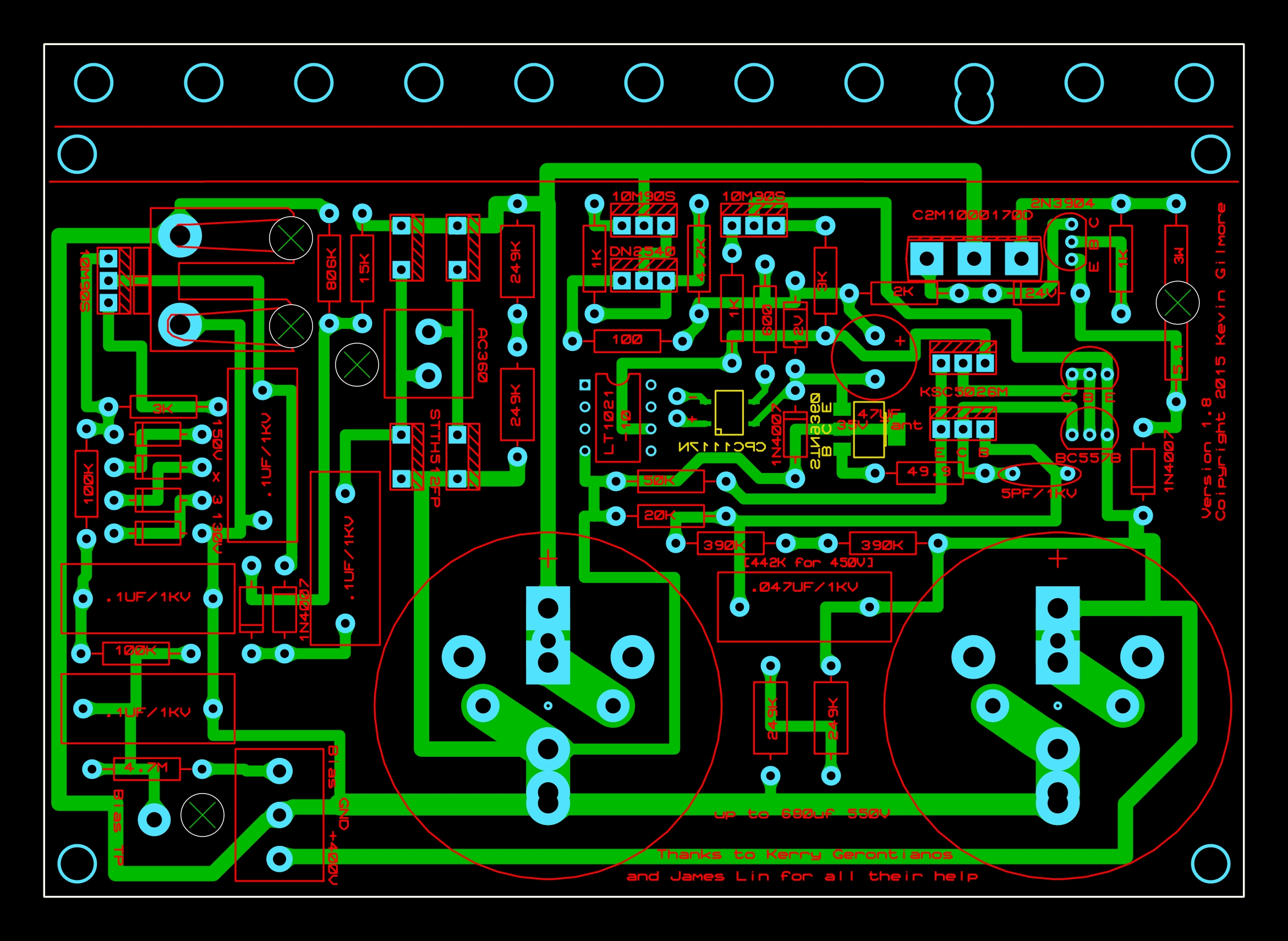
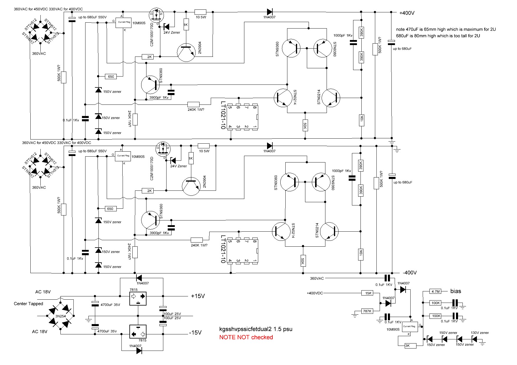
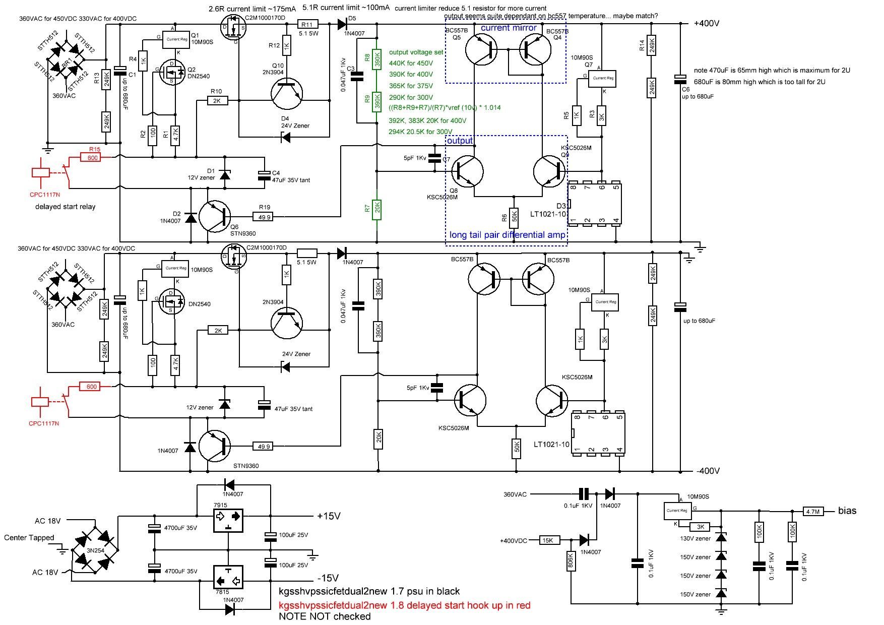
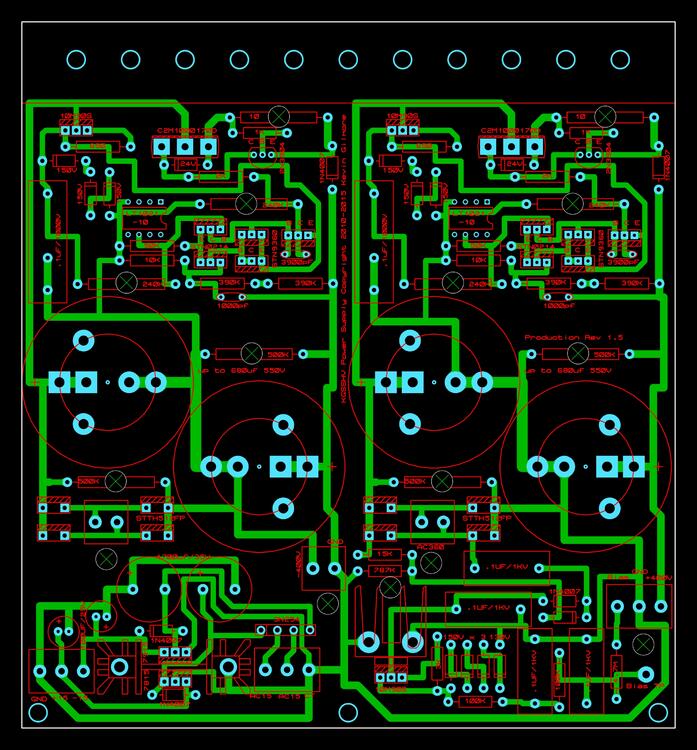
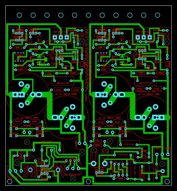
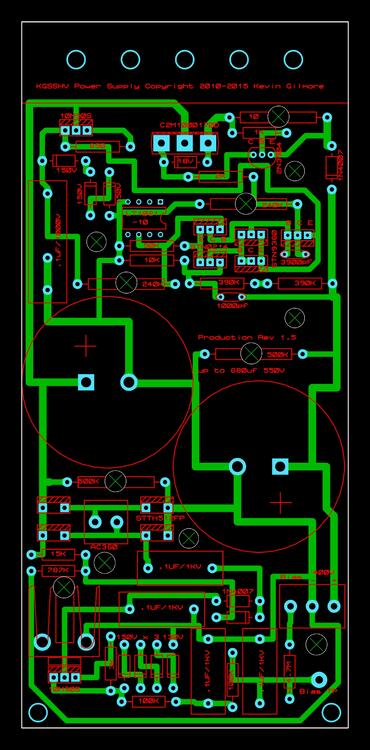
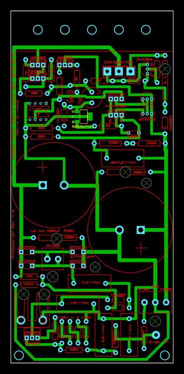
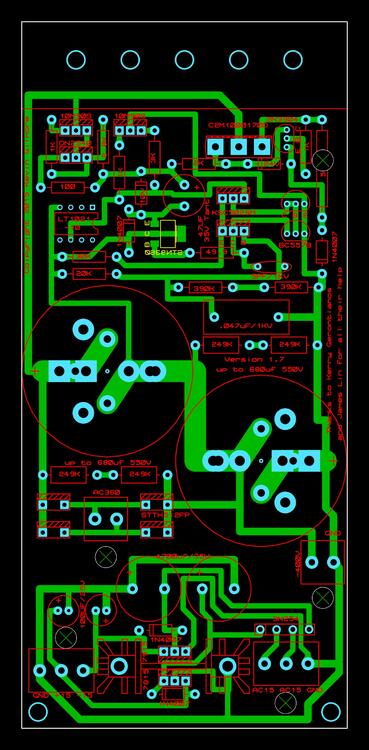
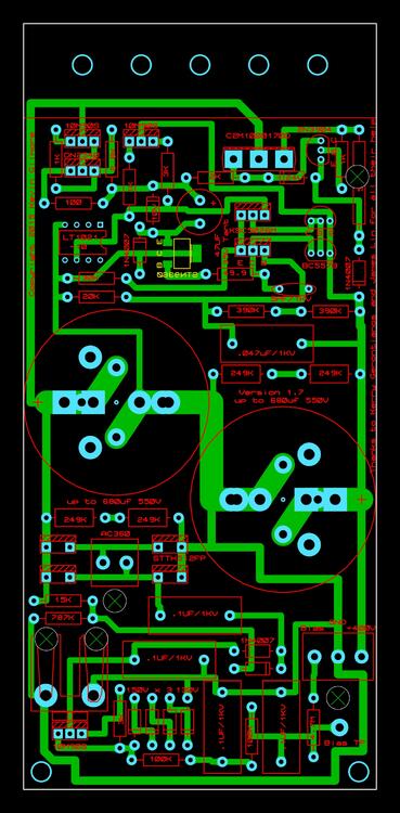
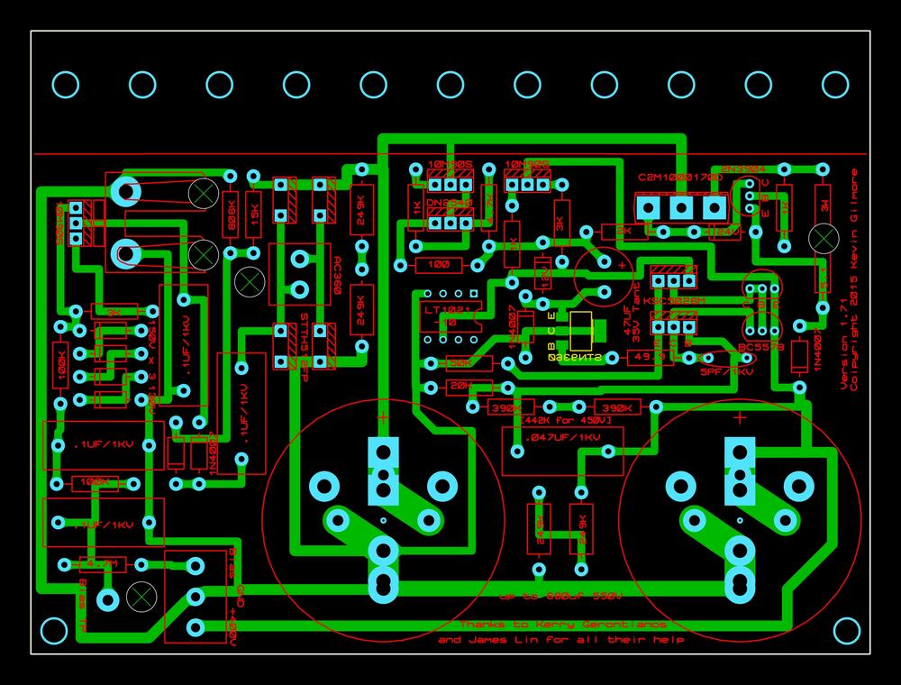
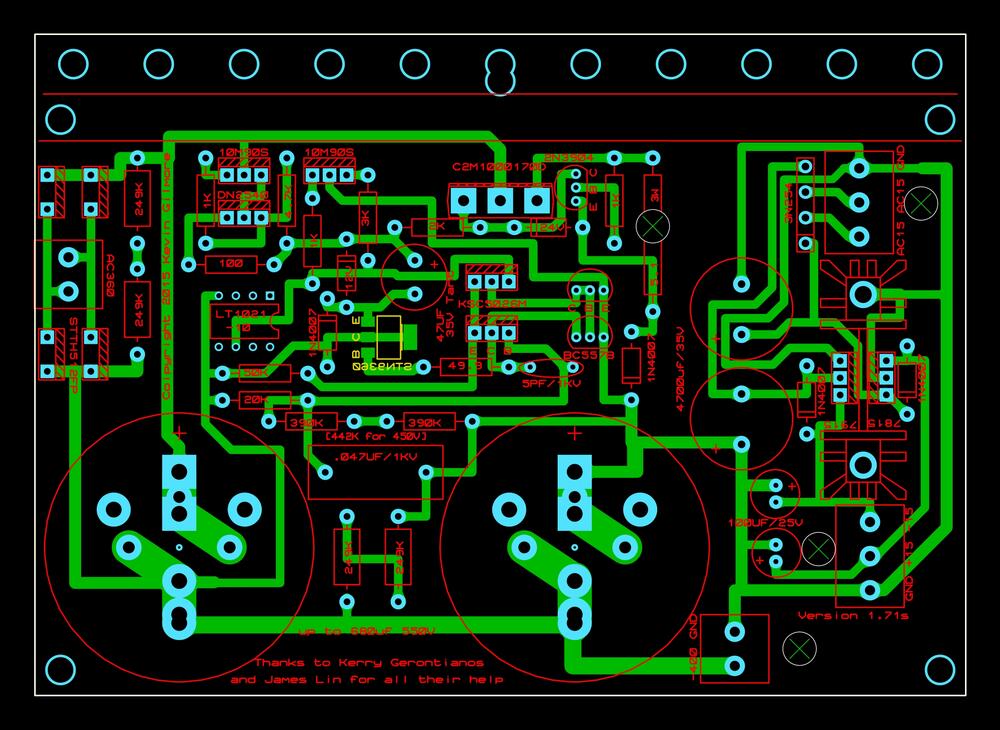
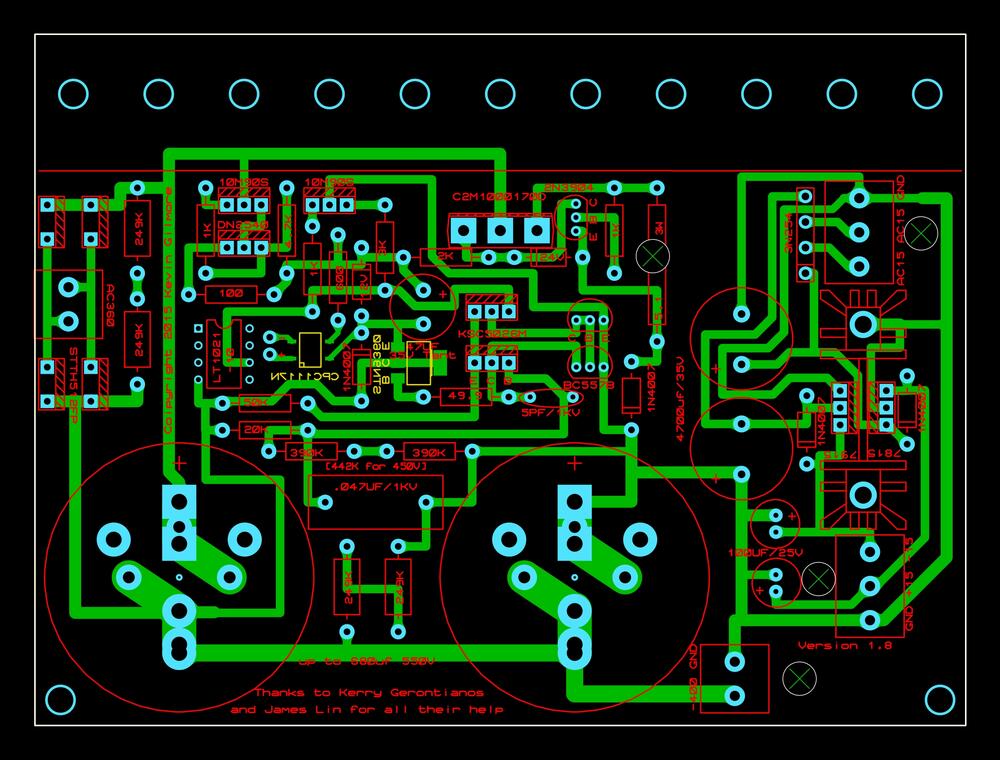
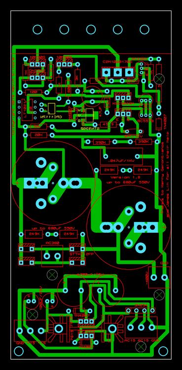
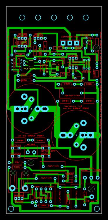
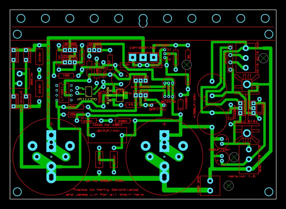
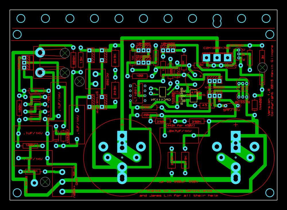
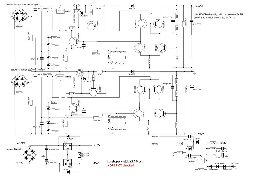
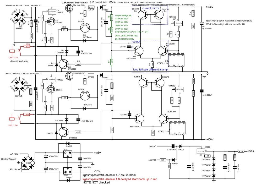
My guide to golden reference high voltage (grhv) variants Here is my attempt at documenting some of the different GRHV board variations. (this will be work in progress for sometime) feel free to private message me with any additions comments, corrections etc. please note the schematic for version 1.5 has been reverse engineered by me from the gerbers and may contain error(s). location of the gerbers: https://drive.google.com/drive/folders/0B_iJFfZStuVhSE5nOHBVdTByR1k golden reference filename naming guide fat - boards which are wider and have less height than the non fat variants L bracket mounting only same as the non fat variants. fat with S as the last character of the filename - boards which are wider and have less height than the non fat variants and the height is about 6.3mm less than the fat variant. these boards also feature more screw hole options for the mounting the pcb to the case including an option of not using an L shaped bracket and mounting the transistors directly to the vertical face of a heatsink/side of the case. a silkscreen cut line is included to guide removal of the L bracket mounting roles to facilitate direct transistor to heatsink mounting. dual - has both positive and negative hv supply with additional bias and both positive and negative low voltage supplies on a single pcb left - has a single negative hv rail and both positive and negative low voltage supplies right - has a single positive hv rail and bias no new in the filename version - 1.5 boards high voltage starts instantly board has high voltage VAC power. Topology is much simpler then version 1.7 and 1.8 and therefore not considered golden reference. new in the filename actual golden reference boards with extensive post pass transistor regulation. new without sw in the filename- version 1.7 high voltage starts instantly board has high voltage VAC power. new with sw in the filename - version 1.8 or later boards same topology as 1.7 but high voltage will not start until dc power supplied to the cpc1117n no dual and no fat in the filename - minimal width and quite high. NOTE placement of the screw terminals for input VAC can vary considerably depending on if the board is a fat, fat S or non fat. Overview of the versions It is the extensive post pass transistor regulation that marks the golden reference out from the other power supply designs as such version 1.5 and earlier not classify as a golden reference since they lack any post pass transistor regulation. No details of versions before 1.5 or version 1.6 could be found in the gerber archives. Apparently pre 1.5 versions had on board heatsinks and ground lanes but there gerbers and not available in the google drive archive. No schematic could be found for version 1.5 although after reverse engineering it was found that the circlotronps.pdf is similar in topology but modified to support 900V output. No bill of materials could be found for version 1.5 and it is not certain what is the power rating for the larger resistors. All versions have the pcb tracks on the underside with no tracks on the top. All versions have no ground plane ALL versions have bleed resistors to help discharge the high voltage caps although version 1.5 and a few variants of 1.7 use a single high power resistor and the rest two 1/2W resistors in series. All versions have the same basic voltage regulator based low voltage positive and negative supplies All versions have the same bias supply although v1.5 has different resistor values. ALL versions use a LT1021-10 voltage reference All the versions 1.5, 1.7 and 1.8 use a C2M1000170D pass transistor All the versions use a 10M90S pre regulator although version 1.5 controls it with a zener string and 1.7 and 1.8 control with a DN2540. 1.7 and 1.8 are almost identical in topology although 1.8 does not automatically start the high voltages. DC must be applied to the CPC1117N to start. note 1.8 does not have provision for screw terminals for the DC to switch on the cpc1117n. versions 1.7 and 1.8 have more post regulation using a second 10m90s (which is not present in version 1.5) after the 1N4007 protection diode. version 1.5 uses a 10ohm current sense resistor and versions 1.7 and 1.8 use 5.1ohm by default. version 1.5 uses a 10K resistor to ground in the 3 series resistor chain to decide the output voltage, 1.7 and 1.8 use 20K to get 400V output. The other 2 resistors in the chain are the same for version 1.5 and version 1.7/1.8 version 1.5 uses two stn0214 which are replaced by two KSC5026M in v1.7/1.8 version 1.5 uses two stn9360 which are replaced by two BC557B in v1.7/1.8 Known non golden reference boards which are variations or predecessors to version 1.5 and golden reference variants NOTE These have not been looked at in detail by me or fully reverse engineered. The cyclotron power supply series follows a similar evolution to the golden reference. earlier cyclotron psus (circlotronps.PDF) use a variation of version 1.5 topology with modifications to bring the output up to 900V. However since it lacks any post pass transistor regulation it can not be considered a golden reference these psus do not have new in their name. The later cyclotron power supplies have the words new or newver in their name on quick inspection of the gerbers appear to be modifications for 900V of the version 1.7 power supplies, have post pass transistor regulation and may be considered golden reference variants. The filename conventions follows the guide above with dual, single, S and SWS versions available. circlotronhvpowerdualnew.zip appears to be derived from the version 1.7 topology with a similar complement of transistors. On the underside of the pcb there are two additional stn0214 transistors compared to the version 1.7 plus 3 mount points for a total of 500V worth of smd zeners. circlotronhvpowerdualnewer2.zip ditches the zener string and introduces another stn3960 and includes sw and sws variations. The kgsshv8g.pdf power supply appears to be an predecessor version of version 1.5. There are very close similarities in topology including no post pass transistor regulation. Current sense is still controlled by a 2n3904. The pre-regulator is 10m90s controlled by a zener string and a quad of transistors like the version 1.5. However the pass transistor is two parallel fqpf8n80c. The control transistors are 2sa1486 instead of stn9360 and 2sc3840 instead of stn0214. Both types of control transistor are no longer in production and hence the conclusion this is older than version 1.5. Apparently these boards are classified as KGSSHV ------------------------------------------------ Version 1.5 boards ------------------------------------------------- predecessor to the golden reference with no post pass transistor regulation the board uses a single high wattage bleed resistor for each cap uses multiple stn9360s, stn0214s uses a serial zener string for to control the 10m90s pre regulator. LT1021-10 voltage reference based single sided board kgsshvpssicfetdual2.zip this has both positive and negative rails, a simple voltage regulator based low voltage positive and negative supply and 580V for stax headphones bias board size approx. width 152.7mm height 165mm silkscreen revision 1.5 kgsshvpssicfetsingle2.zip this has a single rail identical to the kgsshvpssicfetdual2 in topology and 580V for stax headphones bias board size approx. width 76.5mm height 165mm silkscreen revision 1.5 ------------------------------------------------ Version 1.7 boards ------------------------------------------------- considered the first known golden reference board version (given the lack of information on version 1.6) has extensive post pass transistor regulation. the board uses two serial bleed resistors for each cap uses a single stn9360s and multiple BC557B and KSC5026M uses dn2540 and 10m90s for stage early voltage control for the input to the c2m1000170D LT1021-10 voltage reference based double sided board kgsshvpssicfetdual2new.zip this has both positive and negative rails, a simple voltage regulator based low voltage positive and negative supply and 580V for stax headphones bias board size approx. width 152.7mm height 165mm silkscreen revision 1.7 kgsshvpssicfetsingle2new.zip this has a single positive rail identical to the kgsshvpssicfetdual2new in topology and 580V for stax headphones bias board size approx. width 76.5mm height 165mm silkscreen revision 1.7 single bleed resistor for each cap kgsshvpssicfetsinglenewleft.zip this has a single negative rail identical to the kgsshvpssicfetdual2new in topology and has a simple low voltage positive and negative regulators based supply board size approx. width 76.4mm height 165.3mm silkscreen revision 1.7 kgsshvpssicfetsinglenewright.zip this has a single positive rail identical to the kgsshvpssicfetdual2new in topology and bias supply board size approx. width 76.4mm height 165.3mm silkscreen revision 1.7 kgsshvpssicfetsinglenewleftfat.zip this has a single negative rail identical to the kgsshvpssicfetdual2new in topology and has a simple low voltage positive and negative regulators based supply board size approx. width 138.7mm height 103.1mm silkscreen revision 1.71 kgsshvpssicfetsinglenewrightfat.zip this has a single positive rail identical to the kgsshvpssicfetdual2new in topology and has a 580v stax bias supply board size approx. width 138.6mm height 103.1mm silkscreen revision 1.71 kgsshvpssicfetsinglenewleftfatS.zip this has a single negative rail identical to the kgsshvpssicfetdual2new in topology and has a simple low voltage positive and negative regulators based supply has more mounting options for the pass transistor, 4 holes for mounting to a case and can be used with or without an L shaped bracket board size approx. width 138.7mm height 98.6mm (slightly less height than the fat non S version silkscreen revision 1.71s kgsshvpssicfetsinglenewrightfatS.zip this has a single positive rail identical to the kgsshvpssicfetdual2new in topology and has a bias supply has more mounting options for the pass transistor, 4 holes for mounting to a case and can be used with or without an L shaped bracket board size approx. width 138.7mm height 98.6mm (slightly less height than the fat non S version silkscreen revision 1.71s ------------------------------------------------ Version 1.8 boards ------------------------------------------------- same topology as version 1.7 making this a golden reference board adds a cpc1117n and 600ohm resistor to control high voltage startup the high voltage will not start-up automatically. This negates the need for a external relay for delayed start-up and just requires dc power to be supplied to the cpc1117n (not present in earlier versions) for the high voltage to start-up. if you want the board to power up instantly simply omit the 600ohm resistor and cpc1117n and it will act just like the version 1.7 instant start boards. boards same size as the equivalent version 1.7 pcbs silkscreen 1.8 there does not seem to be a dual version of this board kgsshvpssicfetsinglenewleftSWS.zip this has a single negative rail almost identical to the kgsshvpssicfetdual2new in topology and has a simple low voltage positive and negative regulators based supply board size approx. width 76.4mm height 165.3mm silkscreen revision 1.8 kgsshvpssicfetsinglenewrightSWS.zip this has a single positive rail almost identical to the kgsshvpssicfetdual2new in topology and has a bias supply board size approx. width 76.4mm height 165.3mm silkscreen revision 1.8 kgsshvpssicfetsinglenewleftfatSW.zip this has a single negative rail almost identical to the kgsshvpssicfetdual2new in topology and has a simple low voltage positive and negative regulators based supply board size approx. width 138.7mm height 103.7mm silkscreen revision 1.8 kgsshvpssicfetsinglenewrightfatSW.zip this has a single positive rail almost identical to the kgsshvpssicfetdual2new in topology and bias based supply board size approx. width 138.7mm height 103.7mm silkscreen revision 1.8 kgsshvpssicfetsinglenewleftfatSWS.zip this has a single negative rail almost identical to the kgsshvpssicfetdual2new in topology and has a simple low voltage positive and negative regulators based supply has more mounting options for the pass transistor, 4 holes for mounting to a case and can be used with or without an L shaped bracket board size approx. width 138.7mm height 98.6mm (slightly less height than the fat non S version silkscreen revision 1.8 kgsshvpssicfetsinglenewrightfatSWS.zip this has a single positive rail almost identical to the kgsshvpssicfetdual2new in topology and has a bias supply has more mounting options for the pass transistor, 4 holes for mounting to a case and can be used with or without an L shaped bracket board size approx. width 138.7mm height 98.6mm (slightly less height than the fat non S version silkscreen revision 1.8


-
1. part of the headcase experience is trawling a massive number of posts in one thread e.g. the carbon to find out about the grhv. Having a dedicated thread is seen as cheating. 🙂 2. to build a grhv you need C2M1000170D which are out of stock just about everywhere with little hope of being back in stock anytime soon... this is one of the issues delaying my megatron build. I can't comment on any sound quality differences, but there very few options if you want a 680uF cap that is 550V and will fit in a 2u case, i.e. be about 65mm in height or less. 450V or better 500V would be fine for the output cap with 400V output. The + lead of the input cap is connected to the centre pin of the large C2M1000170D. Output cap + lead is connected to the cathode of the IN4007 protection diode that is directly inline with the 5.1ohm 3W current sense resistor.
-
I get mine from https://www.ebay.co.uk/itm/Stax-socket-5-pin-Pro-Bias-WHITE-Teflon-custom-made/184601921523?hash=item2afb21c7f3:g:CHcAAOSw2ENf7Jyy
-
great in the winter time to keep hands warm. not so sure about the utility in the summer and i hate lugging around the batteries.
-
(I would like to try NOT using my headphones or my ears or any other part of my anatomy) stax amp using multiple parallel push pull ef86 valves.... called the maxi minitron stax amp using push pull 211 valves called the ouch stax amp using push pull 101D valves called the almost-inplausible joking aside, a T2 using golden reference HV supplies (capable of the required +-500V and -560V) and only modern components.
-
if the case has no letter/other designator for the grading then it's almost certainly a fake, (or possibly a reject?). The only time cases for transistors don't have an indication of Beta/hfe/gain or whatever the manufacturer uses to bin and sort them is if the manufacturer does not bin and sort them... e.g. 10m90s, C2M1000170D etc etc.
-
If you are a reviewer maybe its a problem. If your aim is to get enjoyment from listening to music and your enjoyment is improved by hi-end hifi equipment that you can afford to buy then no it's not a problem. There is far more to enjoying music via hifi than just frequency response... dynamics, detail, stereo imaging, pure emotional enjoyment, good bass.... Im almost 50 years old and I don't have any meaningful response above 15K and above about 13k im getting rolloff. Do I care... only as much as that like everything else reminds me I am mortal and slowly falling apart. I can still appreciate a T2 over a blue hawaii, a panasonic fr cap over a simlic, a philips nos ecc88 over a electro harmonix 6922.... (or I think I can which for me boils down to the same thing for me). I think that if I was 20 and applied a 13khz high slope cut off I would be appalled at the results. Now I am more than twice that age I live with it. For me what does not make sense is to get into debt for my enjoyment of music. Could I buy a blue hawaii se new... from savings yes... would I no. Would I get a bank loan for one... no way ever. Would I spend time and money over many months buying the tools and skills to build one.. yes and I did. Audio is a journey, I learnt a lot and thanks to that journey I ended up with a T2.... Perhaps Tyll is going through some life changes... it takes a lot of guts to sell almost everything and go "walk about", mid-late life crisis? who knows his real motivations, but sure as heck I would not be satisfied with a bose mini system. what drives me nuts is my hifi never sounds exactly the same day to day week to week... is it me or the hifi, or some environment condition don't know... I just want every day to be one of the "special magic" sounding days, My 2p worth. It's certainly true you do need a bit of a thick skin here sometimes. a few days ago I tried to answer someone's question and got chewed up a bit, I think the chewer either misunderstood what I was trying to say or just wanted to flex their superior electronics knowledge. Made I was angry and hurt for a day or so but there are lots of different personalities here, in the future I will avoid them. I have got so much out of this forum it more than balances out.
-
using mousers parametric search I can't find any vishay resistors !% 50ppm 1/2w 350v working. koa mf1/2 series are same ppm, working voltage and wattage and similar size. https://www.mouser.co.uk/KOA-Speer/Passive-Components/Resistors/Film-Resistors/Metal-Film-Resistors-Through-Hole/MF-Series/_/N-7gz41Z1yzvvqx?P=1yzbppyZ1z0zlrrZ1z0ynpy I use them interchangeably with the Xicon. Xicon is far cheaper if you don't mind buying 100. koa is an option if you want to buy just a few. Per resistor koa is more expensive than the xicon. vishay MBB02070C are close to the xicon 1% 50ppm 350V working but 0.6W https://www.mouser.co.uk/Vishay/Passive-Components/Resistors/Through-Hole-Resistors/Metal-Film-Resistors/MBx-SMA-Professional-Series/_/N-7h7zb?P=1y97ob9Z1z0jjxqZ1yzrof0Z1z0x6pwZ1z0zls5Z1z0wljo (I have not tried these resistors)
-
1. I assume the poster was referring to a circuit diagram NOT the marking on the case of a transistor. 2. I could not be bothered to see if the transistor in question was a bjt, mosfet or whatever. I probably should have put a / between the hfe and the word gain to cover more options. 3. Almost all of kevins circuit diagrams do not specify the transistor gain variant.... 4. I just had a conversation today with someone about transistors and almost every transistor we mentioned we did not put the gain letters on the end because it did not matter for the purposes of the conversation. 5. I completely agree if we are talking case markings then there should be a letter code on lsk389. starcat where you referring to transistor cases without the gain letter or just lsk389 in a circuit diagram or in conversation?
-
lsk389 generic name when you don't need/want to talk about the hfe gain.
-
mains line voltage varies by +-10% or more, transformer output varies with load 10Vac on 475Vac is not going to make much difference....