jamesmking
High Rollers
-
Joined
-
Last visited
Everything posted by jamesmking
-
Glad to help starcat. The Megatron build is in the early stages. Im taking this one slowly because I have been suffering from work related stress for a while now... and don't have the energy to work at my usual build rate. I have reverse engineered the gerbers, built my own circuit diagram and edited the gerber files to my build style. But have not ordered any pcbs yet. Worse im going to use golden reference HV supplies and the world seems to be out of stock of C2M1000170D pass transistors and I don't have any spares. 30 to 40 non fake 2sc3675 ..... wow.... I have a total of 6 in my parts inventory and they came from ebay, I tested them with a breakdown tester and they look ok but that's still no guarantee they are originals. Spritzer on the forum helped me source the transistors I needed for the mostly modern T2 build (he runs a company building stax amplifiers and has a large stock of original genuine parts) but some of the transistors for an original t2 build are getting very very rare. You might want to private message him and see if he is willing to sell you any nos transistors you need. I only asked for very small numbers - just enough to build the T2 plus a spare set in case I messed up. I have also replied to you diy t2 post with a breakdown of what the different versions of the T2 are and the gerbers for them. I assume you are going original T2 rather than the mostly modern version...
-
I built a blue hawaii with golden reference HV supply and the simple voltage regulator based lv supply built into the golden reference hv board. Later I added a golden reference lv supply which improved the sound a bit. I also replaced the diode bridge on the LV with a synchronous rectifier for even lower noise. The blue hawaii is a very good amp. Far better than anything I had listened to previously and was a quite straightforward build I did not modify any of the gerber files. I did solder the leds, the resistors you need to measure the voltage across to set the constant anode current and the adjustment pots onto the top side of the board for easy checking and adjustment. I managed to fit everything into one 400mm deep disapante case The T2 build is by its nature almost twice the size of the blue hawaii and of course more expensive. The pcbs are bigger, there's more values and components and more power supply rails and multiple transformers etc. I also had to modify the gerbers to fit my build style, selected volume pot and the case I wanted to fit the amp into. The T2 is just magical and is my daily listening device. If you only have the time and resources to build one build the T2 and get the best to begin with. I don't regret building the blue hawaii but I have not listened to it since I built the T2. I found the T2 build to be big but not difficult. I read the forum posts carefully followed their advice and used xicon resistors and ultrasonically cleaned the pcbs. I also measured every component with a LCR meter and transistor tester etc before soldering them in and checked everything multiple times... I even tested the zeners and diodes and matched all components between channels and between + and - halves of a channel. I actually finished the pcbs about three weeks before I switched the amp on.. I got locked into a cycle of checking and rechecking everything and was convinced I would get sparking or noise batteries. So far I have had no issues at all with the amp and the initial fear I felt from reading the forum posts on failed T2 builds has dissipated. most importantly the T2 has 4 more glowing valves than the blue hawaii and so looks better in the dark... but then the megatron has even more valves
-
All the T2 amp boards are a single monolithic slab (except the version I modified). The non shrunk versions are more than 400mm deep and will not fit into most diy chassis like the disapante 400mm. Also they have solder pads for a very expensive and now not easily available volume pot. Original T2 uses almost completely obsolete transistors which are both very very expensive (if you can even find them) and almost all the sellers e.g. ebay etc are selling fake parts anyway. t2schem.PDF So if you have not got the transistors already from known good sources you are looking at probably looking at 10-30+ dollars PER transistor and there are a lot of transistors.... The original T2 amp board was massive... too large to fit into a 400mm deep case! so there was also various attempts to make it smaller: t2shrunk.zip Hence the number of different T2 gerber zip files. I would very roughly guestimate budget $1000 just for the transistors for the amp board. If you make a build error and the magic smoke comes out things can get real expensive real quick. Building an original T2 is going to be fraught with danger and failure unless you can find a reliable source of non fake parts or have them already for a know good source. You also need resistors that can handle the high voltages without the insulation breaking down. Xicon 273 series worked for me and KOA mf1/2 seem ok. PRP appear to fail. Joamat plus others worked on a version of the T2 which used mostly still in manufacture transistors but still requires 12 obsolete resistors: staxt2nc3fdh7.zip t2schemmodified.PDF shrunk version 398mm deep: t2shrunk2.zip shrunk version but with solder points for an alps potentiometer t2shrinkedv10.zip This is the version I built. Fortunately I purchased the obsolete transistors from a very well known forum member who purchased them from a known good supplier when they were still available. There is no known version of the full T2 that only uses modern parts.... independent of this there are also three versions of the power supply, (the golden reference power supply series is not suitable because it can't handle the high voltages required for a DIT T2). Joamat et al created a fully regulated version using the lt10 voltage reference: t2250kgsshv.zip t2hvandlvpsukgsshv2.zip (the same reference that is in the golden reference LV and HV boards so I went with this). The other designs use a ref102. t2schempower-2.PDF t2250.zip t2hv2.zip joamat told me the lt10 had lower noise and since I bulk purchased lt10 references I went with his psu boards. I posted the modified gerbers I made and a circuit diagram for the joamat T2 plus power supplies in this thread a short time ago in the diy t2 thread https://www.head-case.org/forums/topic/6837-the-ultimate-diy-a-stax-srm-t2/page/190/. The modifications to joamats gerbers documented in the post to fit my build style (one pcb per channel, no solder points for a pot etc), a few silk screen error corrections and placed a missing track in one of the psu boards and some more ventilation space for the 3W resistors in the psu boards etc etc.
-
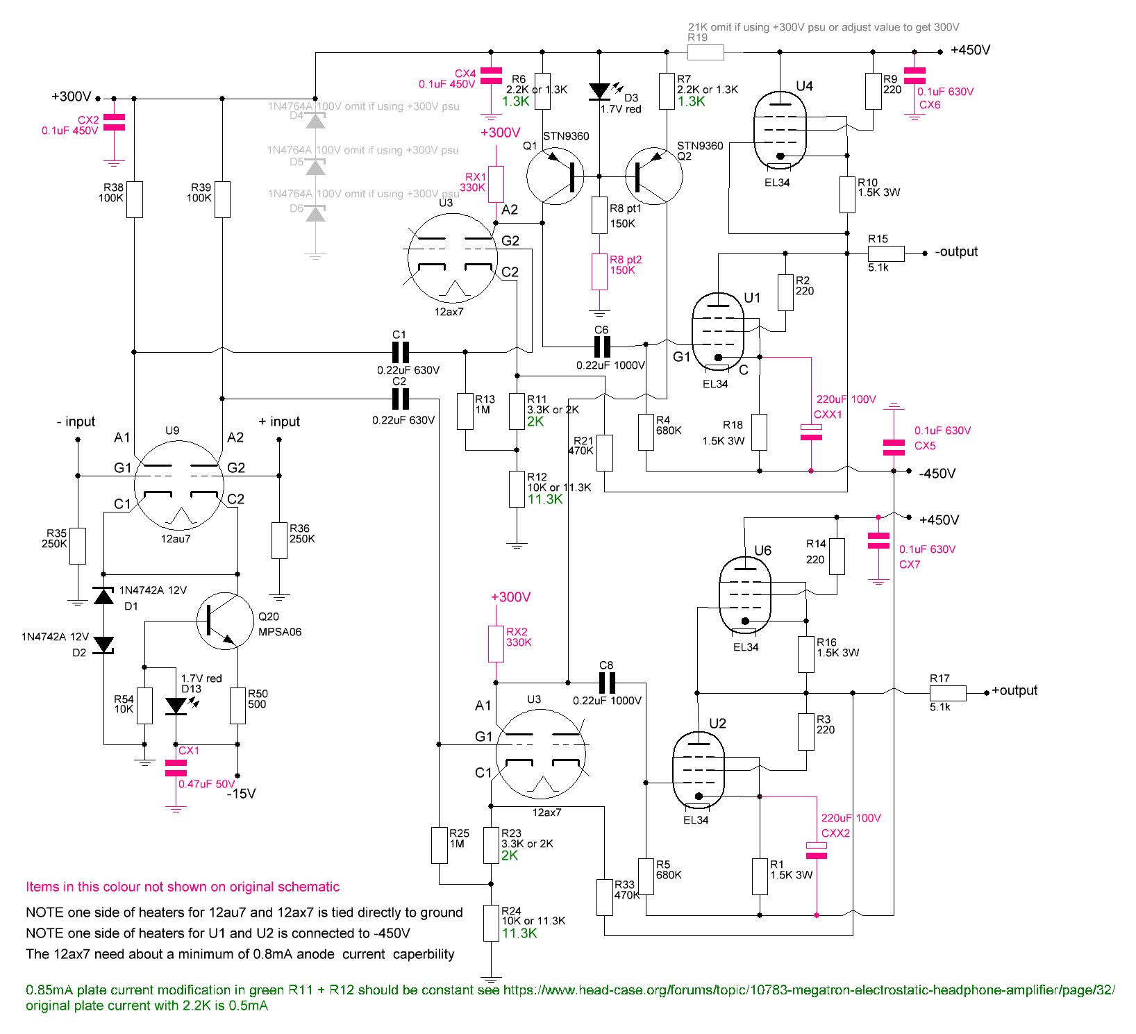
My apologies if this has been asked before.... As normal my first steps in a build is to get the circuit diagram and reverse engineer the gerbers to check them against each other.... looking at the circuit diagram pdf the decoupling caps have been omitted... fair enough, however 1. the circuit diagram shows a single 150K resistor from the led D3 to ground but the reverse engineer of the gerbers has two 150K resistors in series to ground.... 2. the gerbers have two 330K resistors, one each from the 300V line to anodes 1 and 2 of the 21ax7. These resistors are not on the circuit diagram and are used to drop the 300V psu line to down to about 250V for the 12ax7 anode voltage... here is my reverse engineer with components in pink missing from the pdf: NOTE this circuit diagram has not been checked
-
The Gerbers for my T2 build. My T2 has been working without issues for some months now with heavy usage almost every day so I feel reasonably confident about posting the gerbers I used. (see my previous build posts for more details and photos.). full credit goes to Kevin for the original design and joamat et al. for the modifications to modern components. I simply hacked up the gerbers to fit my build style. The amp gerbers are slight modifications of Joamats mostly modern T2 (his build uses all available components except for 4 of 2sj79 and 8 of 2sk216). My modifications include the addition of screw terminals for all voltages, shortening to fit into a hifi 2000 disapante 2U 400mm deep case, split into separate channels, removal of the pads for the pot, wider clearance between components and the ground plane, instructions on the top side for the adjustment pots. T2 left.zip T2 right.zip (note left and right are swappable I just like the 6922 valves at the front) The power supply is also based on Joamats T2 psu, with a couple of error corrections, there was a missing track and a couple of incorrectly labelled components. also the solid state relay in the HV delay section is obsolete and I replaced the footprint with a standard relay. minus and 250v cleaned .zip cleaned t2 hv and lv bias and delay.zip Feel free to use/modify/ignore. I do find that in the power supplies the 3W resistor close to the film cap and zener ladder gets very hot ~90C on the high voltage tails. I have therefore modified the power supply boards to make them slightly longer and provide more space around this resistor and put some holes in the pcb under it for better air flow. minus and 250v cleaned COMP -560v lengthened.zip cleaned t2 kgsshv hv and lv bias and delay comp lengthened.zip I have ordered a set of these lengthened boards but I have not received them yet or made a build using them so if you are going to use them please check them carefully in case I made a mistake. regards and good building James P.S. looks like next on the list will be a megatron build.
-
hmmm... interested.... I will have a look at the build thread, gerbers etc...
-
I have centred the holes and updated my post with a new upload of the gerbers and a new jpeg of the layout. v1.4.zip
-
they all seem to be classified and mobile phone stereo connectors..... and I guess module phone manufacturers do not care about socket robustness... I checked radio spares - same selection as mouser however farnell has https://uk.farnell.com/lumberg/1502-02/socket-3-5mm-jack-4way/dp/1368639?st=3.5mm 4 pole its panel mount but not really pcb mount 😞 same with https://uk.farnell.com/pro-signal/mj-079/connector-3-5mm-phono-jack-4pole/dp/1267373?MER=sy-me-pd-mi-alte just go 4 pin XLR.....
-
the nearest i can find has no thread for panel mounting but is 3.5mm 4 pole, no switching. https://www.mouser.co.uk/ProductDetail/Kycon/STX-35331-4N-TR?qs=sGAEpiMZZMvlX3nhDDO4ANdBTK25DNHDLDgQvn584hU%3D is a 3.5mm socket, 4 pole (3 signals + ground) smd (the picture shows a thread for panel mounting but the datasheet says no thread)... The datasheet implies there may be a variant with a thread but the STX-35331-4N-TR 4N is 4 pole No thread... datasheet: https://www.mouser.co.uk/datasheet/2/222/STX35331-334673.pdf disclaimer I have not actually used one of these, I just did a mouser search and this might fit your needs.
-
I have two blue hawaii se (golden reference hv and lv psus) , two joamat mini t2 (with golden reference hv and lv psus) and a diy t2. I only have experience with them using sr007 mk2 earspeakers. The hawaii is very good, far far far better than the stax srm006 or anything modern stax sells. The mini t2 is better still improving bass, micro dynamics and detail. The diy t2 is fantastic its takes the mini t2 strength and improves on it and adds better macro dynamics, even better bass and detail. If you can get any stax amp get the diy t2. As far as I can tell the sr007 needs as much drive as possible to get the best bass and dynamics and the diy t2 has the drive.... (we are still waiting for Kevin Gilmore to design a single ended stax amp which uses 300Bs or 211s or something even more powerful... 🙂 ) In terms of build difficulty the blue hawaii is probably the easiest (there are two version the original uses obsolete components but the modern version only uses transistors which are still available new), the mini t2 amp boards are almost all surface mount (psu is still through hole) and require precision and a good hot air station. For checking a stereo microscope is very useful. It only uses modern components and costs a bit more than the blue hawaii to build. The diy t2 is not difficult to build (if you use resistors that can handle the voltages) it's just big and intimidating. In terms of build costs the diy t2 is by far the highest. (there are two versions of the t2 one which uses almost all obsolete and very expensive nos components and a more modern version which only uses two types of obsolete transistors.). Either way you need to be aware there are many people selling fake nos transistors which will fail and blow up immediately on switch on or if you are "luckier" fail slowly over time. So you either need a trusted source or a transistor breakdown voltage tester and transistor identifier and even then you are taking a risk... (almost every seller of nos transistors on ebay sells fakes or a mixture of fakes and modern "equivalents" relabeled as originals. In terms of size I built the entire blue hawaii in a single 400mm deep case, the mini t2, transformers in one case and the amp and psu in a single 400mm deep case. Diy t2 transformers and psu in one 400mm case and amp in another 400mm case. (I had to modify the diy t2 amp board gerber files for the amp circuit board to make it fit)...
-
vpi 16.5 with disc doctor record cleaning fluids. I have cleaned my entire classical music collection (1500+ lps) on it. I have two arm wands, one for the cleaning fluid and a seperate one for the distilled water wash cycle. I also use the disc doctor replacement arm wand pads - a lot cheaper than buying a complete new arm wand from vpi. the machine is not that quiet, there are grinding noises from the motor and the vacuum pump is quite loud but it has worked very well for me. I almost had a keith monks. A hifi shop I used to frequent often was closing (the original owner had died some years before and his son taken over but had died) and his grandson was going through the estate. I went through the ex-owners record collection pointing out some of the more rarer and nicer records (they were all played on only high end equipment, cleaned with a keith monks before playing and mint). The grandson was totally clueless about the value of the lps. I assumed he would either sell the collection in parts on ebay or go to a specialist dealer. I purchased a few records myself (I was fairly short of money at the time) and asked about the keith monks. The grandson said it was for sale but had no idea about the price. At the time I did not have enough spare cash to make what I thought would be a reasonable offer i.e. multiple hundreds of pounds. I found out a few days later rather than ebay it the grandson threw it away! He sold the entire record collection I guess about 750+ lps on bulk dirt cheap to a dealer.... sigh A sad end to my favorite hifi shop. I found a while later that someone passing by saw the keith monks in the rubbish skip and took it.... the hifi shop was in a tiny village in the middle of nowhere so I hope it was another patron of the hifi shop. Even sadder (for me) was the ex-owner had made reel to reel recordings over many years of live classical music radio concerts broadcast on BBC radio 3 on agfa pem368 tape ar 7.5 or 15 inches per second, on either a high end teac, ferrograph logic 7 or a tandberg td 20a reel to reels. I asked about these recordings... the grandson said he had erased them all.... sigh
-
cyberpunk 2077 will be out in 2177, this game allows you to explore the historical setting of .......
-
T2 frequency response is at least that good so it's confirmed to be running class AB.... 7K is an awful lot of money that's shop built blue hawaii se with a really nice potentiometer and 0.1% 15ppm resistors. Or two modern full T2s if you go DIY... so its up against the best of the best. 1. does it have interstage coupling caps (bad for sound)? 2. is the signal path cap free? 3. is it using constant current sources? if so where? 4. does it have a 5M ohm resistor on the bias to protect the headphones. 5. does it have 5.1K resistors on the outputs to protect the stax headphones? 6. how quiet are the power supplies? 7. is the B+ delayed on startup? As a speaker amplifier it's interesting, as a stax amp I am not convinced.
-
that's the integrated amp only 4K
-
7K and its BASED on an amplifier that is class AB and has a cheap alps low end pot not even a TKD.... no details of the topology... no photos of the inside.... no details of the voltage swing for the stax... just the bias voltage 0.5% distortion into speakers, ok you might not be able to extrapolate from speakers to stax but... the T2 is much better than an order of magnitude better than that at (0.02% THD) at 575Vrms output. At 600V rms the T2 is starting to clip and even then the THD is still an order of magnitude lower at 0.05% THD and thats over a wide bandwidth of 20 to 50khz... I bet the case is not big enough to fit just the power supply of a full T2 into it.... here is the inside of the amp its based upon https://www.lineartubeaudio.com/products/zotl10-mkii erm where's the power supply transformer?... it has a seperate power supply no details and no photos. "100V / 120V / 240V operation: Auto-switching" ... sounds like a switch mode power supply???? nichicon 85C cap right next to a bunch of valves.... looks legit to me... Wait its a ZOTL design and has no output transformer.... just like the blue hawaii, mini t2, full T2, alpha centauri.... erm just like almost every stax headphone amp... (yes im ignoring the fact its output transformerless into speakers but this is the STAX forum...)
-
nice electrical isolation... I didn't realise fluke had put prototype micro optical isolators into just some of the input jacks...
-
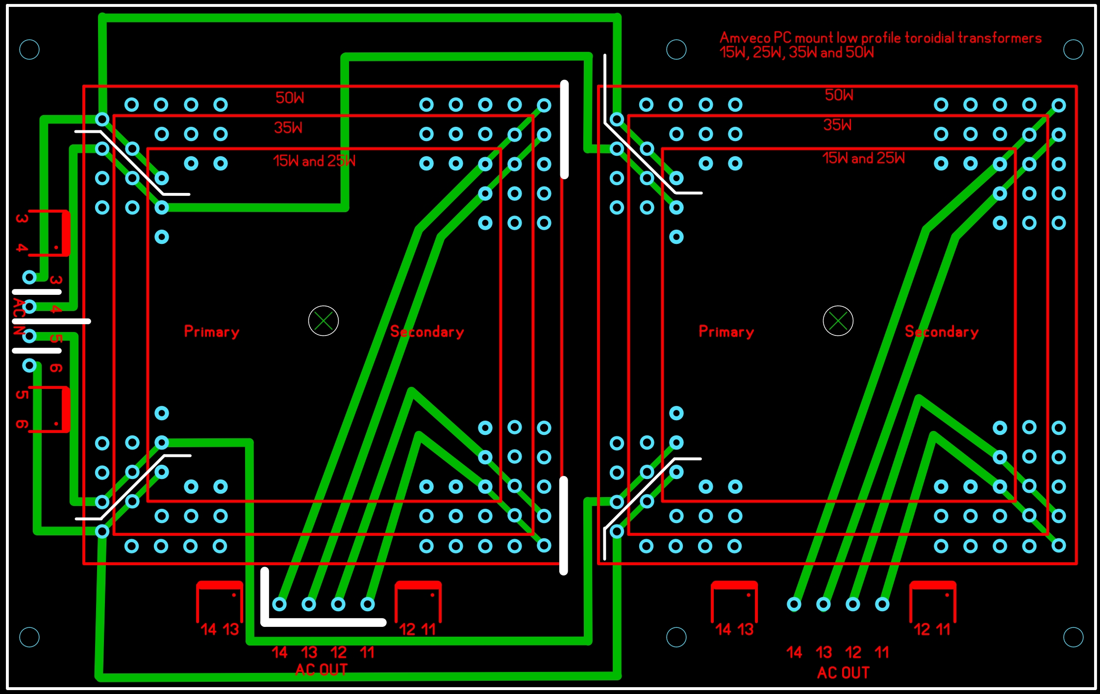
Thank you for the feedback Spritzer, yep I am concerned about that. I'm still working on the track routing.... first priority was getting right the pad placement. v1.3 now has isolation slots and the ac lines rerouted further from the secondary output pins.... I also decreased the ac track width from 1.5mm to 1mm just in the area around the transformer solder pads to give a bit more clearance. The transformers have been moved a bit more apart to increase primary to secondary spacing there too. I have also moved the secondary tracks further from the m5 screw hole. All the tracks are on the underside of the board, I could move the secondaries to the top side as long as the transformers are not going to short to them.
-
The m4/m5 screw hole looks centred in the diagram left to right but not top to bottom... looks like its displaced 2mm bellow centre on the transformer? Slightly larger holes for the transformers and slightly smaller for the 25VA. AC carrying tracks moved further apart. ALL tracks made slightly wider. added transformer windings onto silkscreen. moved mounting holes now centred This zip v1.4.zipcontains the gerber files. The zip needs checking for hole sizes, hole placement etc. Note some isolations slots are 0.5mm. NOTE THIS HAS NOT YET BEEN CHECKED AND VERIFIED.. This needs careful checking to verify pad placement, m4/5 hole placement etc. All tracks are on the underside of the board.
-
I can make gerbers for you - no cost for something simple. If you can post the measurements, hole spacing, track layout etc. PREFERABLY in mm not inches.
-
how is the voltage O- to ground does it behave and vary similarly to the O+? are both channels approximately the same? Unless there is a servo to automatically adjust the offset then you will see some variation with time as the device heats up and reaches a stable temperature. My T2 takes more than 3 hours for the offsets to become mostly stable. Even with a servo there is a tendency for some low frequency oscillation since the servo will alter the current flow and the change in current current flow causes a change in the temperature of the components and temperature change effects the gain and therefore makes the correction over or undershoot - a servo is always chasing its own tail.... Plus unless your valves have regulated heaters, mains voltage varies with time and the variations in the ac heater voltages will affect the valve temperatures and therefore offsets too. You need to put the offset into context. The stax headphones are built to withstand 100s of volts of input. The music signal is going to be far far higher than this offset. For example the T2 is capable of more than 600V RMS output into pro bias headphones... even at very moderate listening levels of say 50Vrms output, 0.1V offset is a tiny fraction of the signal... It's also normal for the offsets to be fairly high (10s of volts) on initial switch on, fairly rapidly decreasing while the valves initially warm up, especially if you do not have a delayed high voltage switch on circuit.
-
4K on a 15.6" monitor is not really going to offer much more than 1080p - 4K only really makes sense on large screens e.g. 32" or more Are you using the gpu for anything e.g. rendering? first person games? - there is not a huge performance difference between the 2070 super and 1650TI. if you are doing colour work you need to know the technology of the screen IPS vs TN IPS is generally more colour accurate AND wider gamult. You need to know the colour gamalt and accuracy. if you are doing lots of cpu intensive work the 8 core will give some advantage. my fear with the Dell is that it is not that well balanced, the 4K screen requires more video memory but the dell has LESS than the MSI, 4K requires more gpu and cpu power but the DELL has less cpu power. My feeling is the dell has compromised on the gpu and cpu in order to fit in a 4k display which you will not get any benefit from (in terms of resolution). The DELL might have better colour accuracy and gamult than the msi if its an ips panel or they may have cheaped out and use a low gamult tn panel. In general laptop manufacturers make it very difficult to get meaningful specs on the screen...
-
low voltage transformer 52mm high 105mm diameter ( I like to run the heaters at a bit under 6.3V AND in my experience the transformers I buy provide a little more voltage than the specs) 2x 4.5A @ 6V for el34s 2x 1.5A @ 6V for 6922s 2x 0.4A @ 15V for balance servo, HV delay circuit and delay relay high voltage 65mm high 125mm diameter (voltages are the same as the psu board silkscreen.) 2x 0.15A @ 260V for +250, -260VDC 2x 0.15A @ 450V for +-500VDC 1x 0.15A @ 465V for -560VDC Both transformers have magnetic shields, electrostatic shields and thermal resettable fuses. transformer manufacturer Mueller rondo in germany http://www.mueller-rondo.com/kontakt.htm With postage and vat slightly under 200 euros for the pair. I like seperate HV and LV transformers so I can run the heaters and LV at full voltage and slowly bring up the HV on a variac when I am doing initial testing. It also offers the chance to easily reuse the LV transformers in other valve amps.
-
The site did an update and there are issues accessing attachments. The admin know and they think its been fixed now.
-
I agree about the low temperatures of the GR psus. In my experience the GRHV seems to generate very little heat (compared to the T2 psu whos 3W resistors are inferno level hot), For my blue hawaii I managed to fit everything including a GRLV, GRHV, transformer and amp boards in a single modshop 400mm deep disapante. For the mini T2 I had to go separate box for the transformers but I still managed to fit the dual GRHV, separate GRHV for the 250V, GRLV boards and amp boards in a single 400mm disapante. In both cases the majority of the heat was from the amp boards and the overall GR transistor temperature levels very acceptable.
-
your not alone, I have the same problem mini T2 thread also has members having issues with attachments in posts that were definitely working previously e.g. bom .xls and gerber .zips.