jamesmking
High Rollers
-
Joined
-
Last visited
Everything posted by jamesmking
-
You can and I have/do. I agree its not 100% reliable in circuit and I know it was not designed to be used testing in circuit. In some cases it will not be consistent when identifying a transistor because the circuit puts it close to the edge case for a recognition and probably has zero input protection but I still have and do find it useful in circuit. Its useful when you have two identical or near identical circuits. You can make comparisons and it at least narrows down what you might have to desolder. In some cases the circuit around the transistor effect the behaviour of the transistor so its miss identified or is right on the border of identification (as stated in the post above). But quite often it will identify correctly and I have never had it identify a bad transistor in circuit as good... its just another tool to be used on special occasions when you know what you are doing and you have to think about the results. For example when testing one of two individual transistors wired as a Darlington pair can identify the single transistor as a darlington. But again if it does the same identification with similar gain on both the good and bad rails then those transistors are likely to be good etc etc. I prefer testing this way than desoldering all the transistors and checking them all. But different people go about problem solving and troubleshooting in different ways. When I know it identifies a transistor correctly and consistently in one circuit and identifies the corresponding transistor in the other rail as two back to back diodes or says the gain in the good rail is say 100 and the gain on the other transistor is 2 then that transistor is suspect and a candidate for pulling and further testing.... (all of which I have experienced) Its more limited when you can't make comparisons between known good and known bad, but if it correctly identifies a transistor type and pin out then a quick look at the schematic for possible other transistors nearby it could be identifying instead then you can be reasonable certain that transistor is ok.
-
I mean just for the -260V / 300V rail. I entirely agree the rest of the psu looks like its working including the -560V rail the +300V rail sits on.
-
You may have done some of these tests already but for the -260V output (i.e. 300+ above the -560V rail, -1 inspect carefully for solder shorts, joints missing solder etc. 0. I would check the AC voltage going in is what is expected. 0.5 check dc voltage after bridge rectifier and smoothing cap is what is expected. 0.6 check the input side of the pass transistor Q19, if Q19 only has say 145V on the input side then it cant be expected to output 300V... 1. I would connect to a variac and see if the psu is actually regulating at 134V or if it varies with input voltage 2. I would check the voltage reference is outputting the correct voltage 3. If the op amp is in a socket I would swap it out for a known good one 4. I would check the voltage drop across the zeners diodes and check the value of the resistors in the voltage divider that sets the output voltage 5. if you have a peak dca75, de-solder the transistors and run an identify on each. I have found that most of the failed transistors I have tested on the dca either show up as back to back diodes, shorts or open, or crazy low gain compared to the spec. 5.1 although not as reliable, you can use the dca in circuit without desoldering the transistors first. Make sure the circuits are not powered and the reservoir caps are fully discharged before running any in circuit tests. if you run dca75 identify tests on the transistors on a known good rail and compare to the corresponding transistors in the bad rail. Any major differences may identify that component as a possible issue, since the rails have identical topology and the low voltage behaviour of all the transistors in the rails should be approximately the same. Do expect some identification fails (device not recognised or no device connected) since you are testing in circuit. But at least it gives you a point of comparison and can be quicker and safer than desoldering... good luck I have not used the DY294 in circuit, I certainly would not advise using any of the breakdown modes in circuit because the voltages used could easily over volt components. The peak dca75 identify function seems to be quite "gentle" and I have used it in circuit on various golden reference lv and hv boards, blue hawaii amp boards etc with no ill effect. Diode testing the transistors is also an option but I have found transistors that have failed but pass the multimeter diode check because they have failed in such a way that they now act as diodes with zero gain. In this respect peak dca75 identify is better. But multimeter diode check is better than nothing. NOTE any depletion mosfets may diode test as shorts or near shorts since depletion mosfets are fully on by default unlike enhancement mosfets...
-
--
-
fair enough, sounds like you are well prepared. good luck with your build and finding the remaining transistors.
-
yep and make sure the silicon you have got is not fake.... This is why I chose to build a modern T2 - which I can highly recommend, I have not compared it to an original T2 but at least I know I all the transistors are from mouser with the exception of the 2sk216 and 2SJ79 which I sourced from a reliable forum member. I know members who have built an original T2 had issues and lost hundreds of $ in burnt NOS transistors... for me the modern T2 makes more economic and practical sense.
-
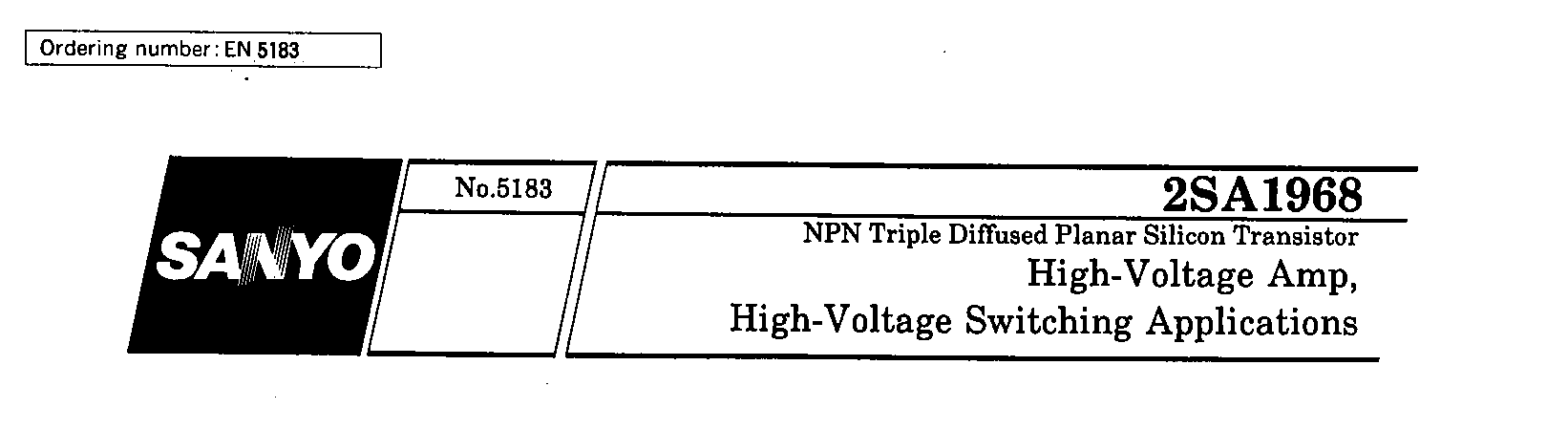
Seriously! OMG how many more bad spec sheets can we find in a week.... ok here's another spec sheet for the 2sa1968 (dated September 1998).. also says NPN... Sanyo datasheet (September 1998) also says NPN for the 2sa1967.... Hitachi datasheet (unknown month 1991) for the 2sa1960 says NPN.... looks like many of the 2sa196X sheets are wrong then...

-
Hi Kevin, I did not realise they where all the same company. 😞 The spec sheet I have (dated 1995 September) says the 2sa1968 are NPN: However we already have a specsheet which can't even get the pinout right for the G3R450MT17D so who knows anymore... Every single 2sa1968 they sold me (54 of them) all tested on the peak dca75 as PNP rather than NPN and broke down at around 200V instead of 900V utter junk.

-
Maybe the seller was just lazy and use a photo from elsewhere? yep my dy294 says around 1520V breakdown into an open circuit, so that's good evidence your transistors have a breakdown exceeding that. Also given the markings look correct I would say you have a winner and the price is not crazy low either. (I don't understand why the 294 displays a 1 in the left most column on the 200V range into an open circuit but does not do this on the 1500V range...). its possible the seller sells a mixture of fakes and non fakes. For example I purchased some 2sk216 and 2sj79 from littlediode on ebay and the sk216s where genuine and the 2sj79s where obviously fake, wrong markings, leads wrong, crazy low breakdown voltage. Returned them. Seller is still selling the same fakes years later. nikko on ebay also sells fakes. For example their 2SA1968 are fakes. they are not even NPN transistors....
-
time to get out the dca75 and dy294. Your photos look consistent with my known good from mouser. If they are fakes they are extremely good.
-
starcat THE EBAY TRANSISTORS LOOK FAKE the sellers negative feedback is also full of warnings of fake transistors, not as described, measured and out of spec, arrived not working etc etc. and many many cases of just not shipping anything at all. My known genuine have: 1. numbers and letters inside the circular indents. there should be left circular indent moulded words china and a single letter code, right circular indent a three digit code again moulded in my case 1 letter followed by 2 numbers. 2. all text should be moulded not printed or etched 3. the manufacturers logo is different 4. the main writing on the lower half of the body should be inside a indented rectangle. All of which agrees with the photos in the posting from John just above and is significantly different from the ebay listing you link to. Production may have changed over the years but I highly doubt the ebay devices are even cree. To attempt to determine if genuine. least reliable visual inspection of case, markings, <- some what reliable but production markings change over the years and some are easier to fake than others. However some fakers are so lazy simple things like the length of the pins, shape of the case are wrong. But the more practiced fakes will take another device with the same case and legs and rub off any markings and print new markings or laser etch new markings. I don't think many if any fakes would go as far as to remould cases. better visual inspection and then transistor identifier like a peak dca75. can identify pin out and type but not breakdown voltage which is important for power supplies and valve amps etc. I have received fakes that don't even have the correct pin out or are not even the correct type e.g. npn when they should be pnp etc etc. But again the more experienced and more prolific fakers will at least provide a fake with the correct type and pinout even if the breakdown voltages, wattages etc are very different. even better a device capable of testing breakdown voltages like a DY294... can provide breakdown voltages but not characteristic curves but this would not necessarily spot a fake that has similar pin out and breakdown voltages but wildly different characteristic curves. even better proper high voltage curve tracer and measure against spec sheet curves and or a known genuine parts P.S. I have reported multiple serial transistor fakes to ebay and ebay do not give a damn. I have tried explaining that not only is it fraud but the voltages involve constitute a potential risk to life and fire hazard... ebay don't give a damn. I went to pay pal... don't give a damn. The issue is many people don't realise about fakes and if they buy and don't test or use them they will probably leave good feedback about the transaction reinforcing the sellers reputation.... I fell into this trap myself when I first started I just did not know about fakes. As an experiment I even purchased over a period of more than a year a few transistors of the same type from the same seller and every time they were fakes. I used ebay returns each time providing evidence from the DCA and DY294 that they where fakes and the seller continued to sell the same fakes year in year out with no problems. I bet they even resold the ones I returned.
-
heads up, more parts (this time SMD) being deleted the 2sc3324 is going the way of the dodo - both the BL and GR grades. its used in joamats mini T2 mouser has plenty of stock of BL but no GR radio spares no stock farnell no stock digikey no stock of BL grade. but has stock of GR grade MMBT5962 is also going. Its used in Mr Carlsons capacitor leakage tester... mouser no stock digikey no stock farnell 3 left in stock radio spares has stock
-
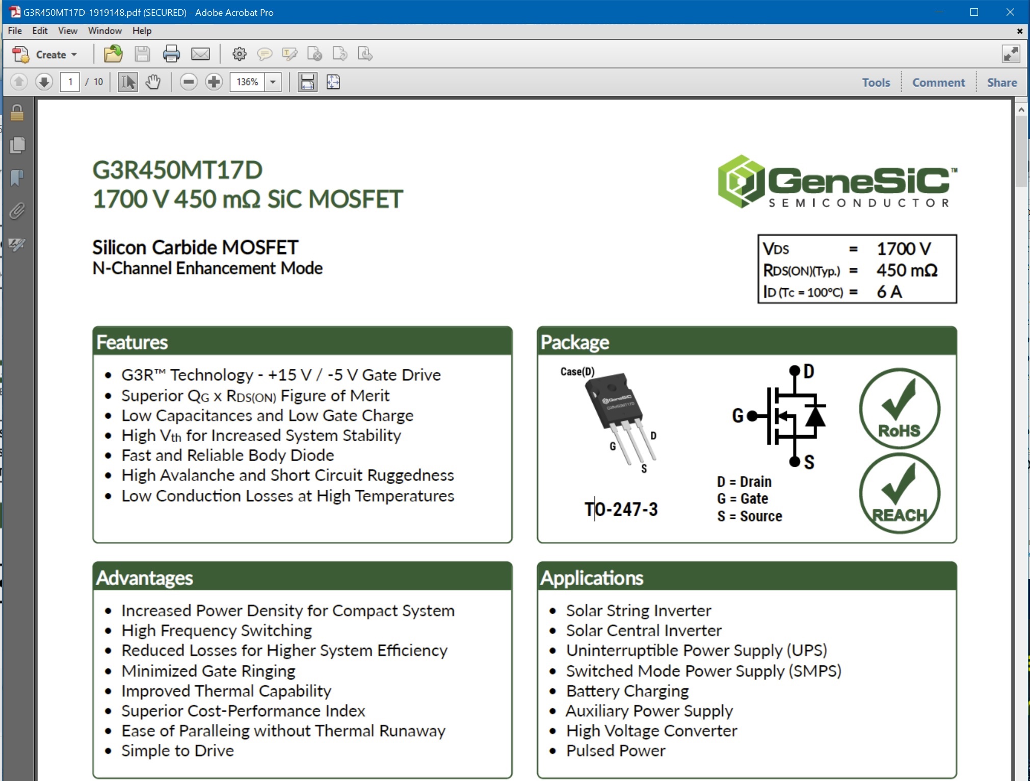
I thought I was going insane. Here's the data sheet from mouser: source and drain are reversed compared to your datasheet for the same product also the current ratings are different WTF GeneSic..... https://www.mouser.co.uk/datasheet/2/169/G3R450MT17D-1919148.pdf

-
The pin out is NOT the same... G3R450MT17D is G S D looking from front left to right C2M1000170D is G D S looking from front left to right. don't worry the C2M1000170D will be back in stock in a few months... maybe.... Update: well I though I had derped but it turns out there are at least two versions of the G3R450MT17D datasheet and they don't even agree on the printout or current handling...
-
the smd version is at https://www.head-case.org/forums/topic/12733-balanced-to-unbalanced-board/page/2/ intermixed with the balanced to unbalanced board discussion. It looks like it is based on the 2017 through hole and does not have adjustment pots for dc offset. The 2018 through hole version has extra circuitry for controlling the dc offset and adjustments pots. I built the through hole version 2018 and found that with a 10K tkd pot on the input it had some high frequency instability with the volume control almost all the way up. I also got some dc offset with varied as the buffered heated up. The transistors gain seems to be very temperature sensitive and although I matched the pnp transistors and matched the npn transistors I could not get a good match between the npn and pnp - the slope of the curves were too different. I don't know if a smd version of the 2018 was released.
-
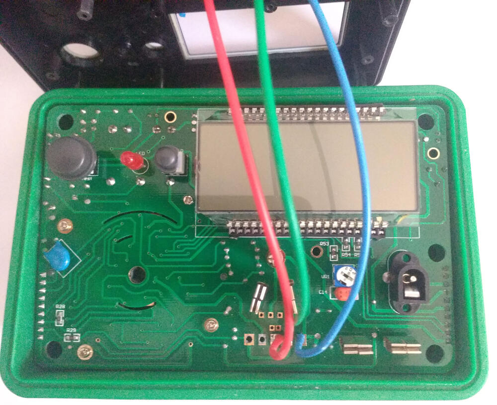
rather than create an adapter I soldered clip leads onto the pcb and ran the leads through the existing holes in the plastic case: The clips also allow me to use adapters for sot23 etc etc. (the same adapters I also use with my peak dca75 transistor tester and identifier)

-
I agree a lot comes down to how much you are going to build and your budget... however sometimes solderwick cant cut it. I once soldered an octal socket on the wrong side of a 2mm 2oz copper board.... solderwick that out 😱 desoldering station to the rescue, board and socket survived. the socket was ptfe round pin with tight pcb holes. 😬
-
good soldering technique and understanding what is going on when you solder: (a little wordy, somewhat dated and slow paced but the latter part of the video has lots of useful info). I heartily agree a good quality temperature adjustable soldering iron is essential and it will make soldering easier, more consistent and you will get better joints. Something along the lines of the hakko fx888d (although the use interface is horrible) that has descent power and is reliable and has repeatable temperatures. also good quality solder and good quality flux I would add a good quality multimeter, one that will not blow up in you hand if say by accident try to measure a 400V psu rail when the meter is in resistance mode... and yes I am speaking from experience here.... I was tired had already lecturer for 9 hours that day. its not cheap but I really like the brymen BM869s. - or one of the lower end models they seem to be very well made and robust. If the multimeter supports temperature probe(s) all the better for verify transistor case temperatures are not excessive etc. joe smith one you tube has done some excellent videos comparing and torturing multimeters for reliability and high voltage tolerance. for proper verification of stability, checking for clipping, etc a signal generator and scope are necessary. For a signal generator the bare minimum would be the analog output of a sound card on a pc and some software to generate sine waves, triangle and square. given the high voltage outputs and rails the scope needs to have switchable x1 and x10 probes (x10 is actually divide by 10 so you can get 400V down to a more manageable 40V). Scopes can be dangerous to use since the ground wire on the probes is actually earth referenced and is clipped to something in the circuit which is not at earth potential you get the possibility of a short to ground.... Some form of desordering to 1. fix mistakes, 2 make repairs. The cheap option is solderwick or a spring loaded desoldering pump. The far more expensive option is a desloldering station. For me using a soldering iron and solder wick has resulted in to many lifted tracks and is too slow and clumsy. something like this works well and is worth its weight in 2sj79s. There are many similar types out there. it is temperature controlled and has a vacuum pump to suck out the solder. For safety a variac is also very useful it allows you to slowly increase the voltage going into the psu so that if there is an issue it would hopefully manifest at lower voltages and hence reduce the collateral damage once you get more serious a transistor tester and identifier can be very useful especially to check for bad components or to post mortem when the "magic smoke comes out". It can also do small signal transistor and led matching. if you are going to do any surface mount soldering there are multiple ways to do it. fine tip soldering iron, hot air station, reflow oven. Magnification is useful - . The cheap ones can be really uncomfortable and can slide off your head easily but if your eyesight is not 20/20 I find them essential for surface mount and for generally inspecting joints etc. now some "luxury" items to make life easier etc The duoyi allows you to test high voltage zeners and also aids in detecting fake old stock transistors by providing non destructive transistor breakdown voltage testing. The instruction manual is crap and the sockets are junk. But with some modifications it works well. another luxury is an LCR meter - this can allow you to match capacitors and inductors and also can measure lower capacitances e.g. a few PF than a multimeter can manage. It can also measure the effective series resistance of caps and other parameters so you can compare caps and identify worn out caps in old equipment. super luxury items because you are addicted to building: distortion analyser super luxury? ultrasonic cleaner. flux residue can result in joints degrading over time and at the voltages some stax amps work at e.g. the T2 the residue can conduct and cause failures. super luxury: sometimes the provided gerbers are the wrong shape, don't fit your style and you wish you could change them. Sprint allows you to import gerbers, modify and re-export. Its relatively cheap. https://www.electronic-software-shop.com/lng/en/electronic-software/sprint-layout-60.html?language=en super luxury: sometimes you want to make your own schematics: https://www.electronic-software-shop.com/lng/en/electronic-software/splan-70.html super luxury: hands free thin probes for smd or when you don't have 3+ hands available. (The same company also sells hands free multimeter probes). disclaimer, all items shown here I own personally and use regularly. However, other builders may have their own favourites and peoples priorities and build styles vary. So these are suggestions and nothing more.
-
GR78xx and gr79xx are surface mount versions of the golden reference LV without the input or output smoothing capacitors. In general the golden reference LV come in dual (both positive and negative supplies on one pcb) or separate plus and minus pcbs. The gerbers can be found at: https://drive.google.com/drive/folders/0B_iJFfZStuVhSE5nOHBVdTByR1k the latest dual golden reference that I know about is goldenreference6D.zip this is marked on the pcb as version 0.45: the dual output board has provision for 25mm diameter input smoothing cap and optional output on led. https://drive.google.com/file/d/0B6JqIzEX9jZ0LTQ4ZG9HTDE2U0k/view?usp=sharing the individual rail pcbs are goldenreference6minus.zip and goldenreference6plus.zip: https://drive.google.com/file/d/0B6JqIzEX9jZ0ejFrM2lQZnFMa0U/view?usp=sharing https://drive.google.com/file/d/0B6JqIzEX9jZ0R1NpaDNuSzl4NHM/view?usp=sharing there is a goldenreference7plus.zip and minus but the pcb markings for them say 0.43 and do not have an option for a led showing the output is on, however the board allows for a larger diameter input smoothing cap at ~35mm diameter. https://drive.google.com/file/d/0B6JqIzEX9jZ0UFRaQzJSd1UwOTQ/view?usp=sharing and https://drive.google.com/file/d/0B6JqIzEX9jZ0YksyazZ0QXZ5djg/view?usp=sharing
-
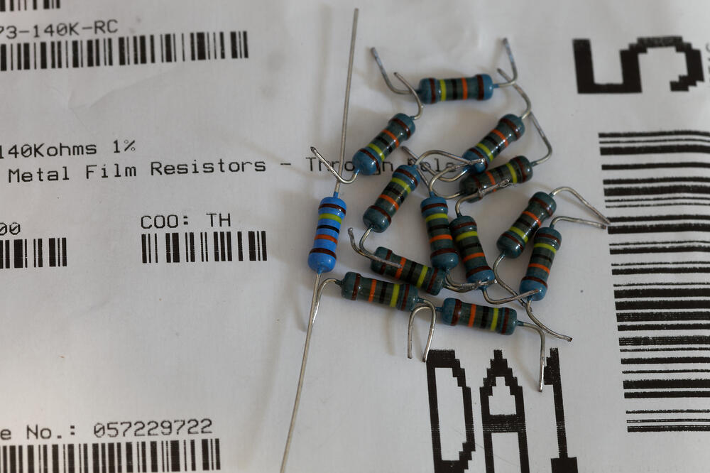
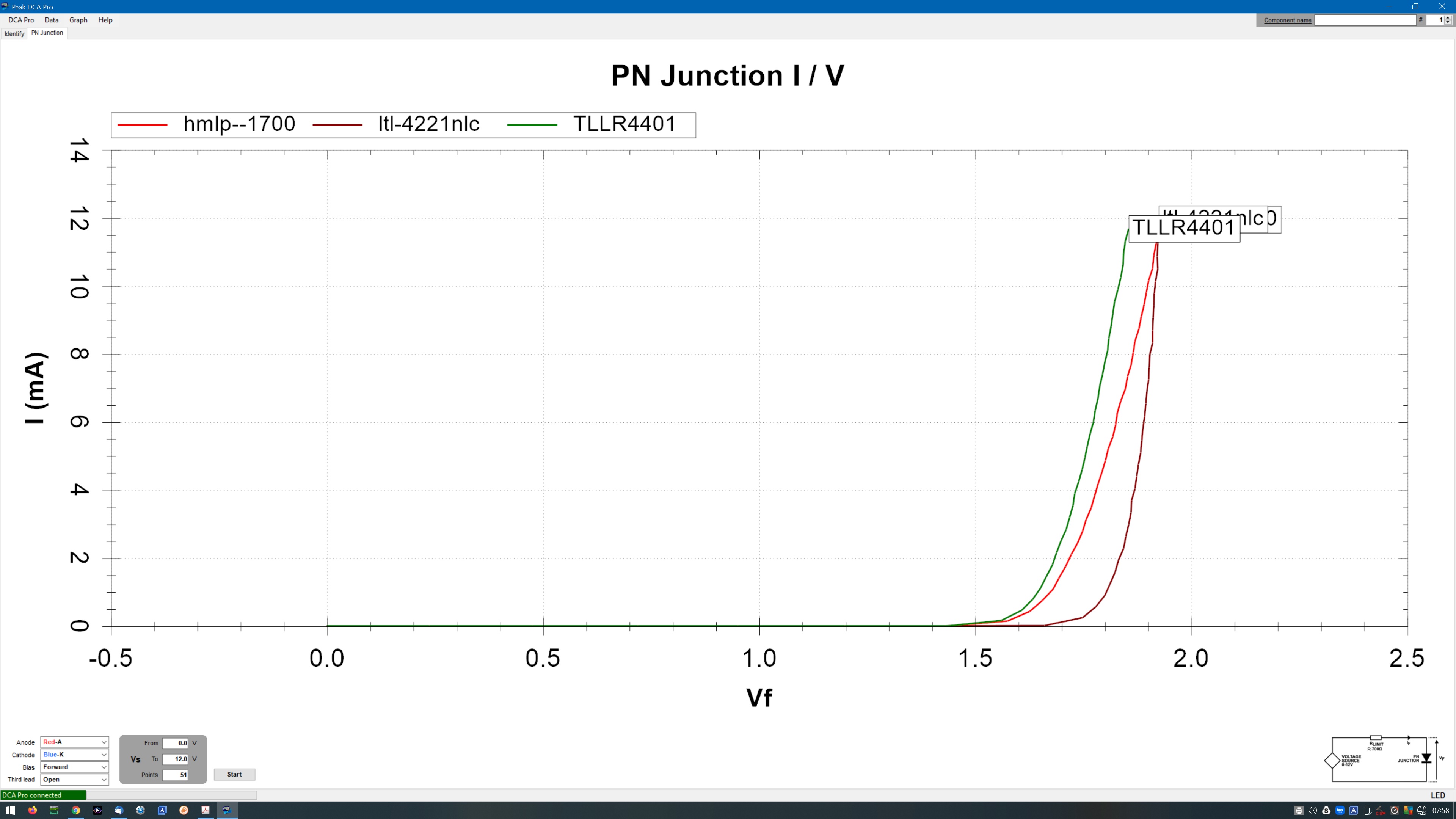
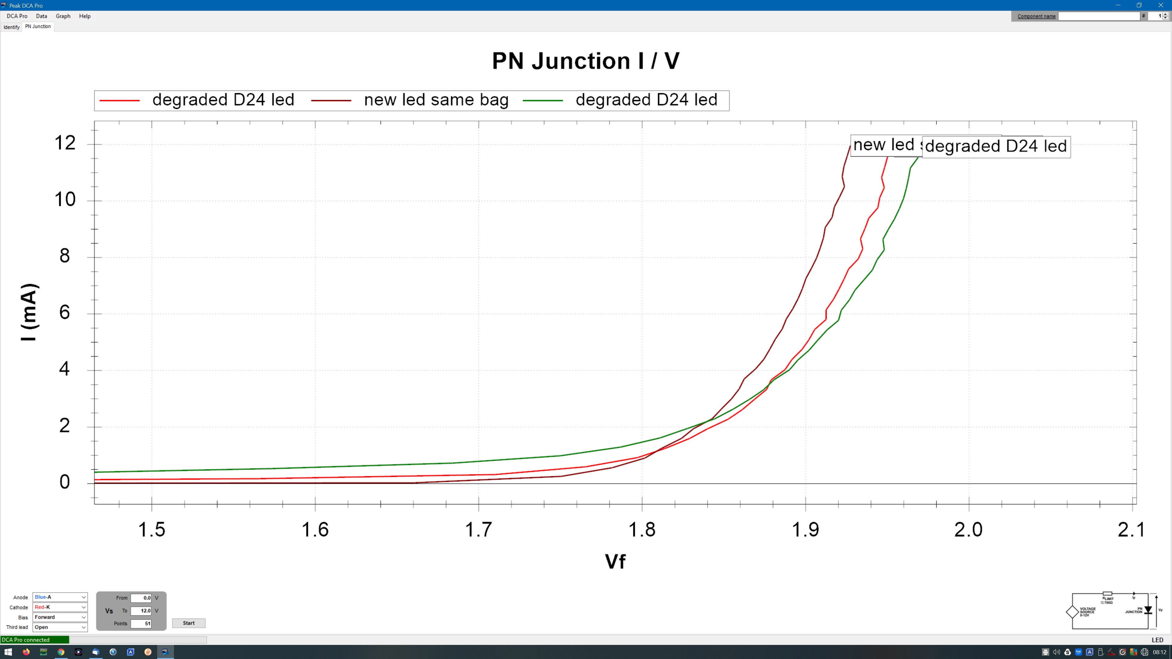
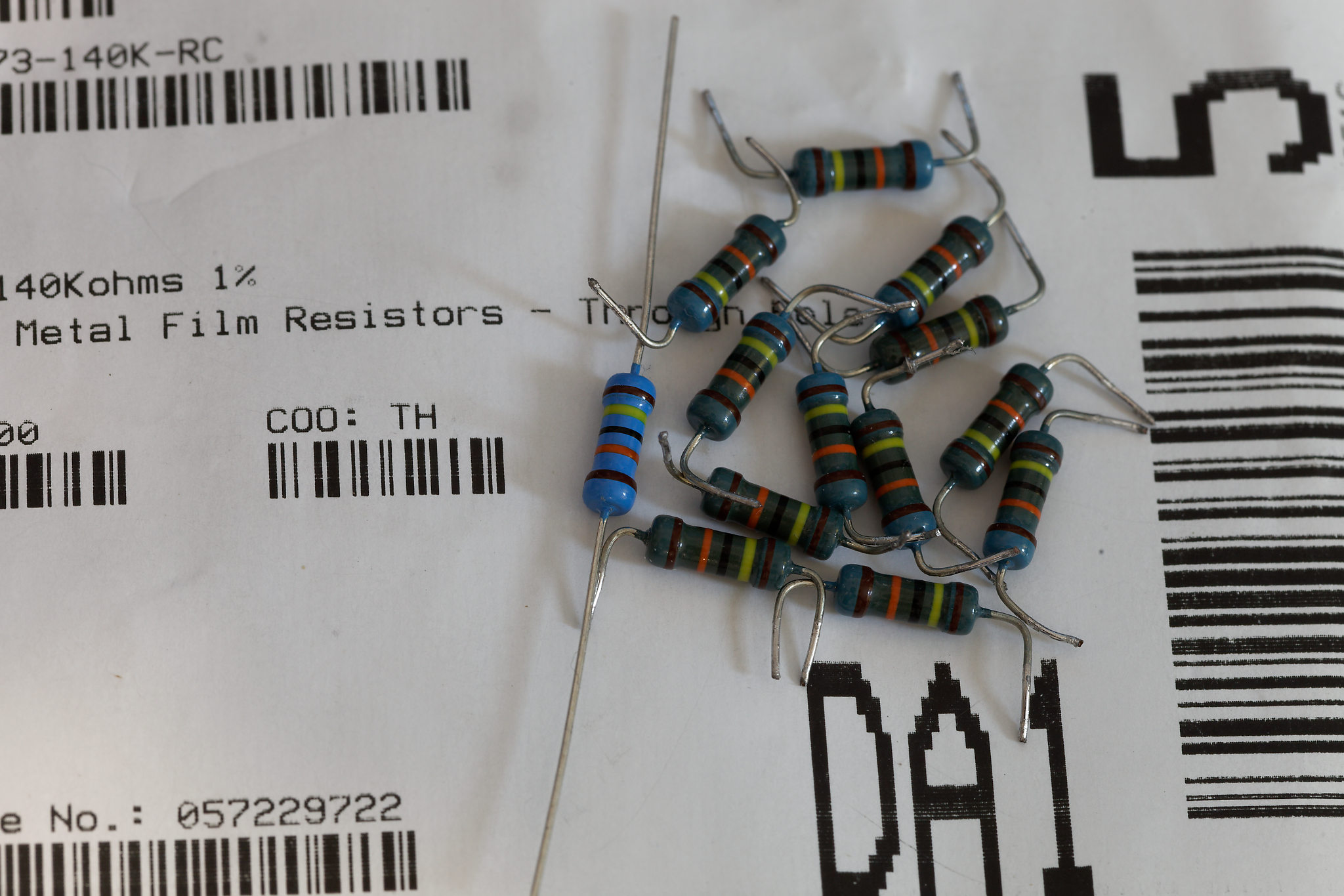
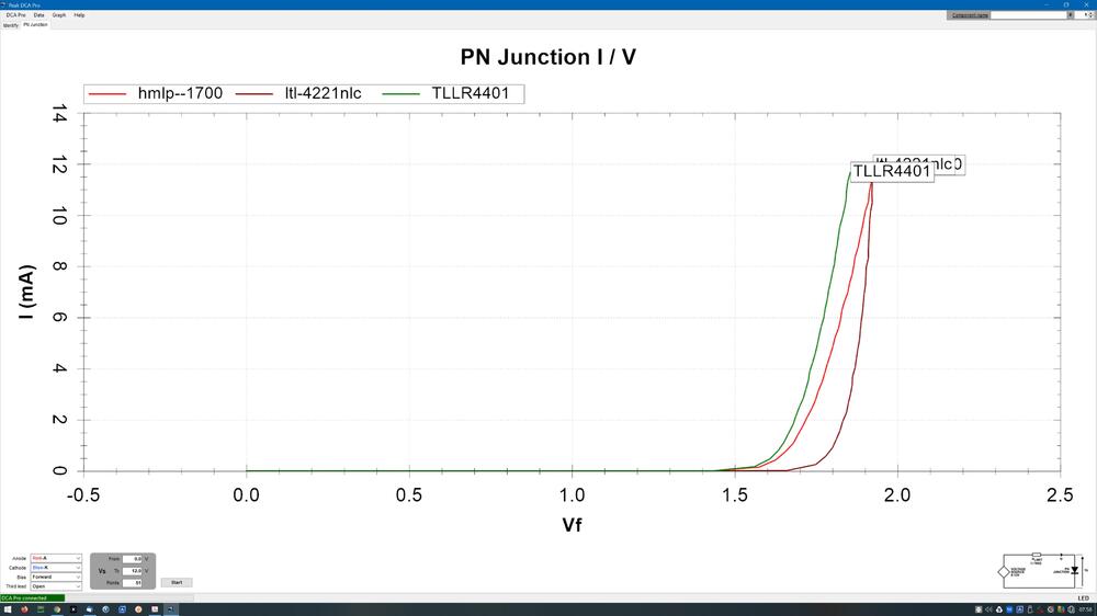
the fresh led has a sharper curve than the used ones, I am zoomed in on the curve, If we look at the full curve the LtL-4221nlc is sharper compared to the HLMP-1700. The TLLR4401 looks promising but is also not quite as sharp. I almost feel like putting 2 pin sockets in the D24 position and trying different les to discover which sound best 🙂 Xicon 273 series. Although discoloured they are not burnt. The drift from new was less 140.5K -> 141.5K so not actually that significant. I did place them on the underside of the pcb. This time I'm placing on the top side and I think that will be enough. Although 0.42W through a 0.5W part is still a little close to the limits for my tastes. I have modified my gerbers to include 4mm airflow holes under each pcb. I think one day I will build a second T2 with some modifications built in.
-
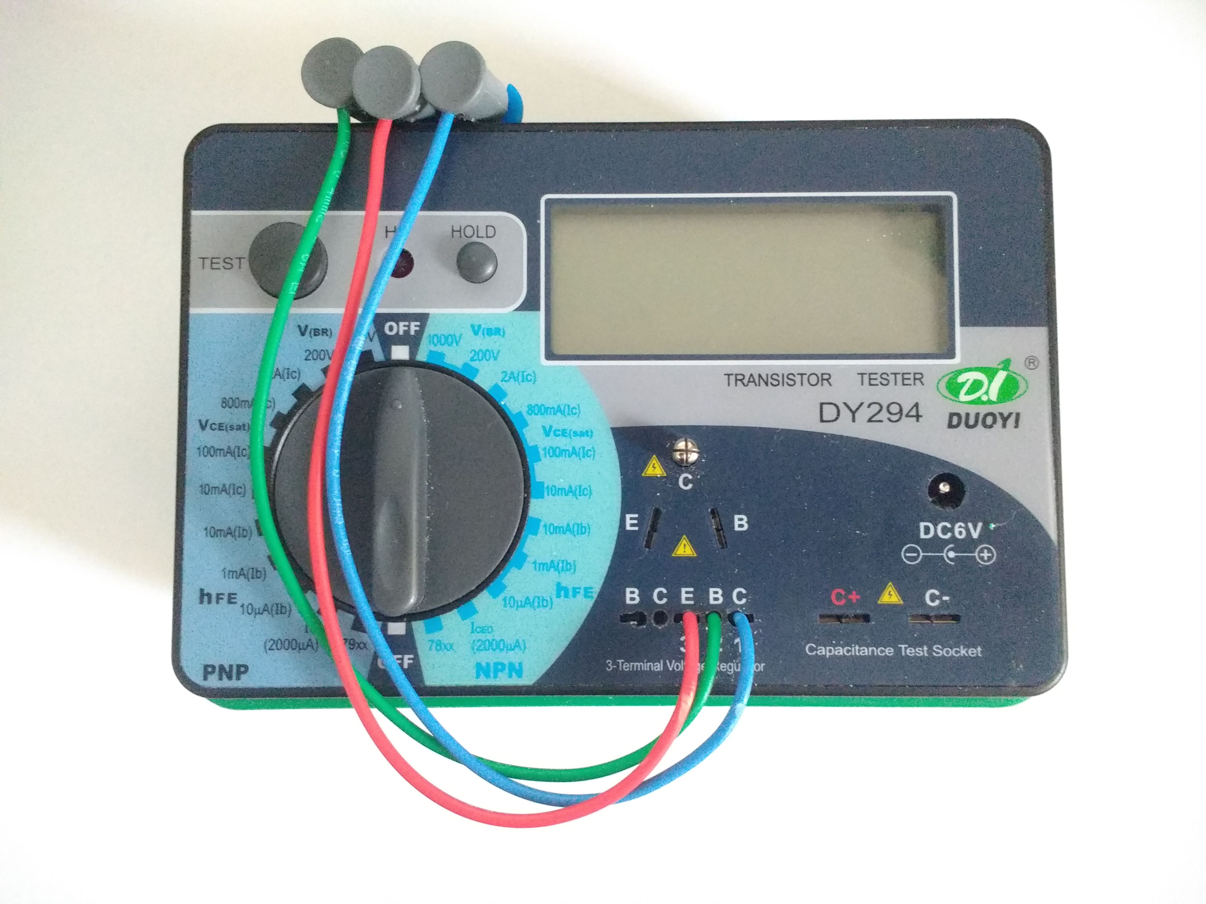
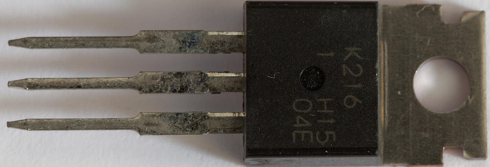
the style of that 6 in the 2sk216 seems a lot different from mine. But maybe they changed font... perhaps its a 7s2sk216 (7 2sk216 is series. in a single package)... 🤪 I just tested a few of mine. Setup on the DY294 : selected NPN gate and source connected to the emitter on the dy294 drain connected to collector on the dy294 and I get around 230V breakdown. spec sheet says 200V.... ----------------------------------------------------------------------- My peak dca75 in identify mode says the following: N-Ch Enhancement mode MOSFET Vgs(on)=0.557V at Id=5.01mA and Ig=0µA Vgs(off)=0.080V at Id=5.3µA gm=25.6mA/V at Id=3.0mA to 5.0mA Rds(on)=6.1Ω at Id=5.0mA and Vgs=8.0V with body diode
-
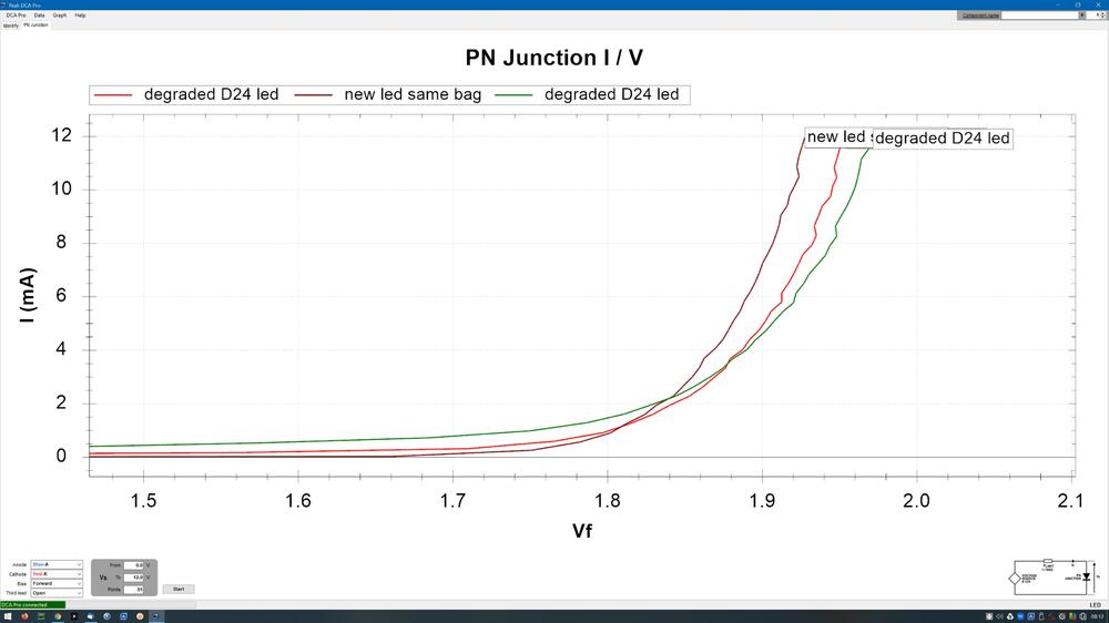
I think it might well be thermal. About a month ago I replaced the groove tube el34s with modern production branded mullards and the bases of these run far hotter than the groove tubes so that could also have contributed more heat conduction to the leds... I did match all 6 leds in the amp by curve tracing on a peak dca75. The other 4 leds still work well and have very similar voltage drops meanwhile both the D24 leds (which are positioned close to the El34s) degraded. I did not raise any of the leds off the pcb and I think there was excessive heat conduction from the pcb into the underside of the led. This time i'm using leds from the same batch but have raised them off the pcb and time well tell if they degrade. I carefully de-soldered the degraded leds and curve traced them. As expected their characteristics had considerably changed compared to the rest of the leds in the bag. The D24 led on the left channel which is closest to the EL34 had the most change from new and the lowest voltage drop in circuit 1.4V in circuit, the righthand channel D24 is a little further from the EL34 and in circuit had 1.5V drop and is a little closer to a new led which has a drop of about 1.7V in circuit. To put the change into context I measured multiple leds from the bag and the curves almost superimposed over each other. So the drift in the D24 leds is significant.
-
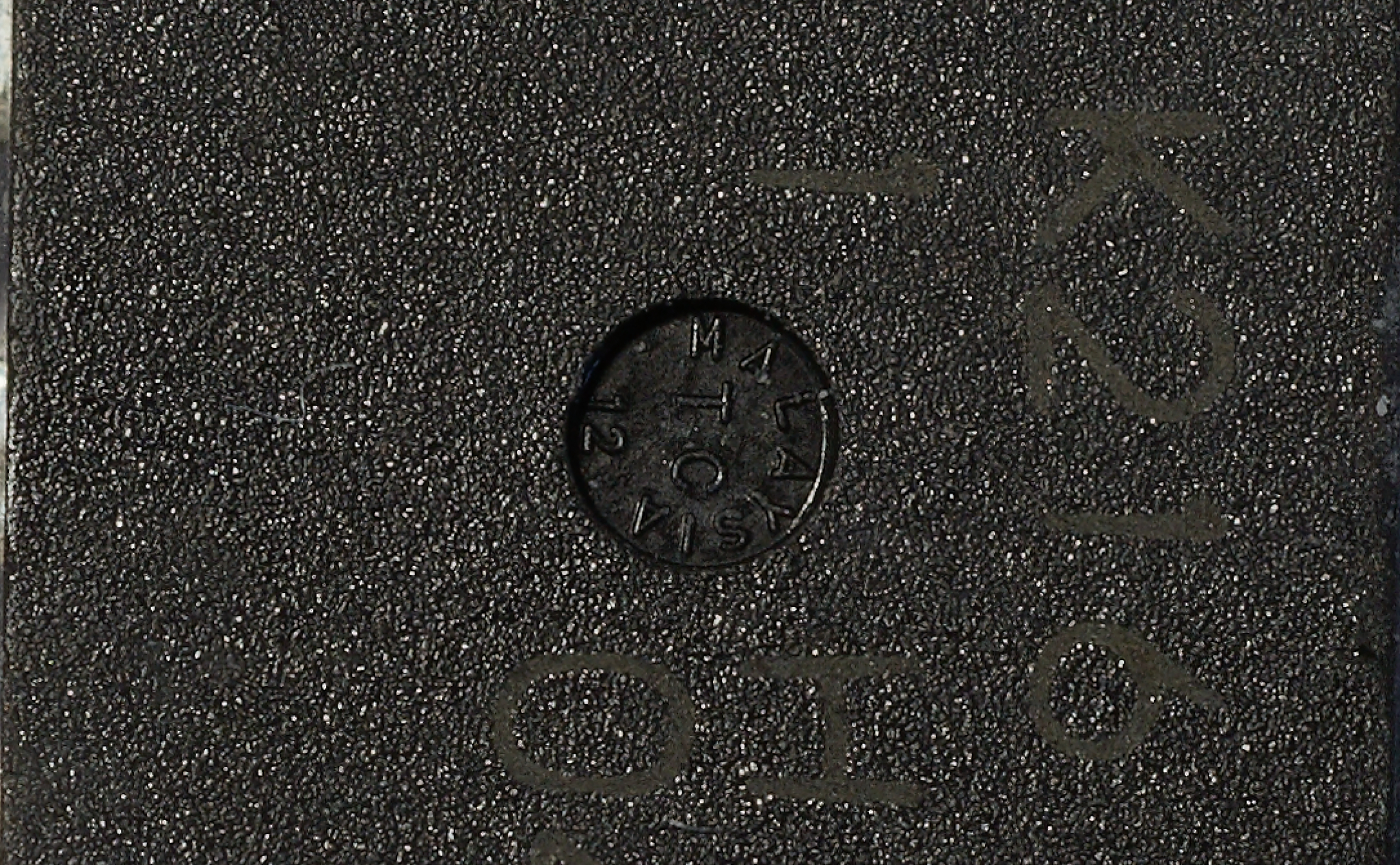
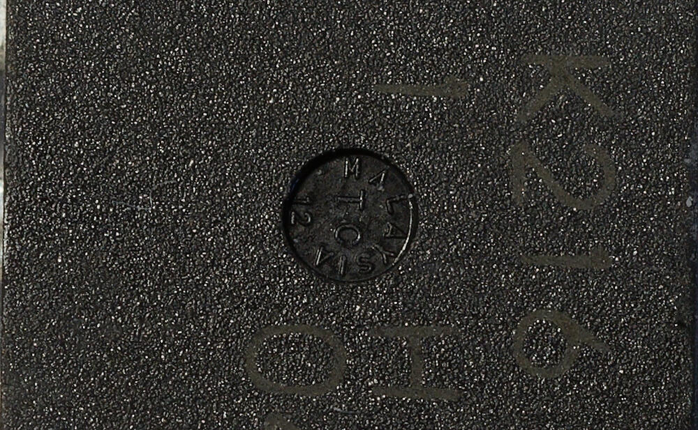
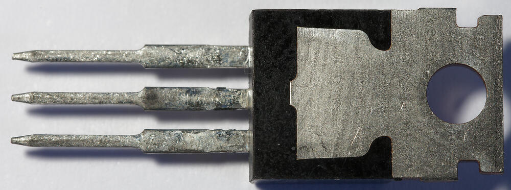
testing breakdown voltages would be a good idea. Fingers crossed you have a real ones. Here is some high resolution photos of a known good one from a reliable source- and its brothers are working my T2... Markings are printed not etched and are a greyish cream colour not white. (photo has been colour balanced). Ends of legs are fairly sharp. close up of the circular area in the middle. Lighting adjusted to make the text in the dimple more readable at the expense of the printed markings. Text in the dimple is raised. The starting angle relative to the top of the transistor for the word MALAYISA and the associated number and letters in the dimple varies between the 216s I have.
-
happy birthday Kevin, thank you for bringing so many diy projects to life and for you advice and troubleshooting help.
-
Longish term modern DIY T2 reliability. I estimate its been used around 8+ hours (and more often than not 12 hours) a day almost every day since I built it. yesterday I took it apart for cleaning. I noticed all four 140K resistor strings connected to the voltage reference in the virtual batteries where somewhat discoloured.... hmmm... on further testing I found the D24 led on both channels did not light up at all not even dimly. :-(. but the amp seemed to work and sounded good. (on the left is a brand new resistor from the same pack as the 140Ks I removed from the virtual batteries.) I checked also psu voltages - good. I measured the voltage across the D24 led- about 1.4V. When the amp was originally built these leds definitely glowed as strongly as the others. All the leds where tested before soldering in and were from the same bag I even hand matched them just for overkill. The D24 leds are part of the circuit that provides base voltage and current to transistors that provide feed into the virtual batteries. I checked the virtual batteries - all were 741V on startup and the adjustment pots could adjust the output. So the batteries look good despite the slightly cooked resistors. I removed the voltage references and tested them in a glden reference LV - all good. The discoloured resistors can be explained by the fact they have about 0.423W flowing through them excluding base current draw from the 2 transistors and are on the underside of the board with little airflow - maybe1W would be better or some airflow holes in the pcb, or mount them to the topside of the pcb. So I decided to de-solder the 140K resistors for measuring and the 140K resistors have drifted slightly but all measure within 141.5K. So a little cooked but probably not the case of the problem. But why are the leds not lighting.... Looking at the circuit diagram the D24 leds should get about 0.5mA current excluding any draw from the bases of the transistors. (560V / (560K *2 resistor string to ground). I used the exact SAME leds for the other positions and it also looks like those leds get about 0.5mA excluding base transistor draw and they glow nice and bright. I de-soldered the leds and tested the D24 resistor string to ground. They spot on resistance and have not been damaged or drifted and so should provide 0.5mA current draw through the led. However the desoldered D24 leds would not glow at all with diode check on my brymen BM869s multimeter but do pass current and are not open or shorted. I tried my keithley 2015 in diode check mode (it has adjustable test current) and got absolutely no glow at 10 or 100micro amp but did get strong glow at 1mA - same situation on both D24 leds. I tested my remaining leds from the same bag and they glow on the brymen admittedly fairly dimly, and glow on the keithley at 100 micro amp again dimly but visibly. (I did test all of them on the brymen before soldering into the amp). So the leds in D24 have degraded over time . I used the same leds in the other places in the amp and they are all fine. This would explain why the batteries are working but the leds are off.... So the plan is to do some more testing on the leds and replace them with another model. But what's causing the leds to degrade in brightness on the -560V rail when the others have not? any ideas? regards and and I apologise for the long winded post James Update: I replaced the D24 leds... they now light brightly with a voltage drop across them of about 1.7V. I replaced the resistor strings with the same resistors but now placed on the top of the pcb, raised from the pcb by about 1cm. After a ten minutes with no lid on the amp the resistors reach 65C on the top and 71C on the sides. So its easy to see how on the underside of the pcb with the lid on they could reach temperatures which could cause discolouration.