


jamesmking
High Rollers
-
Joined
-
Last visited
Everything posted by jamesmking
-
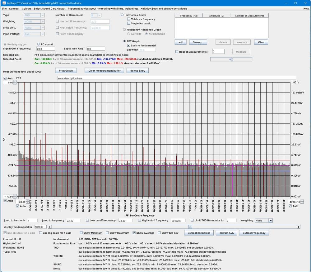
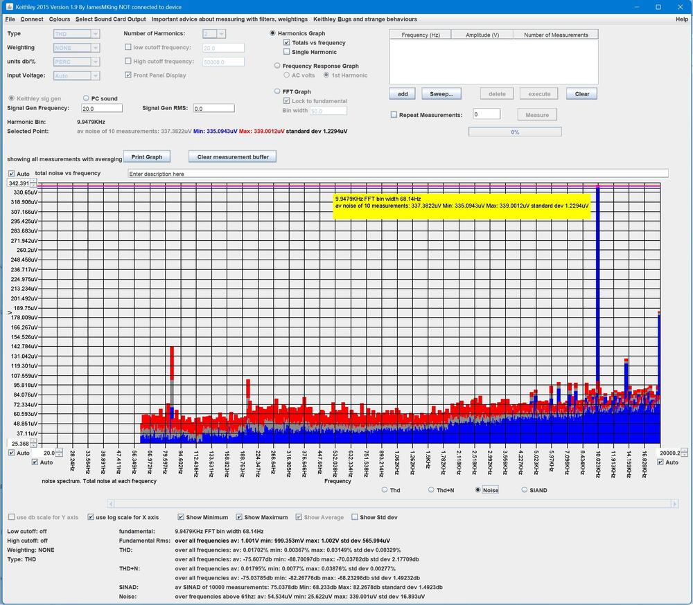
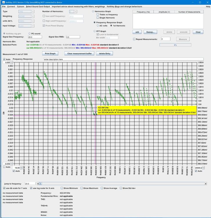
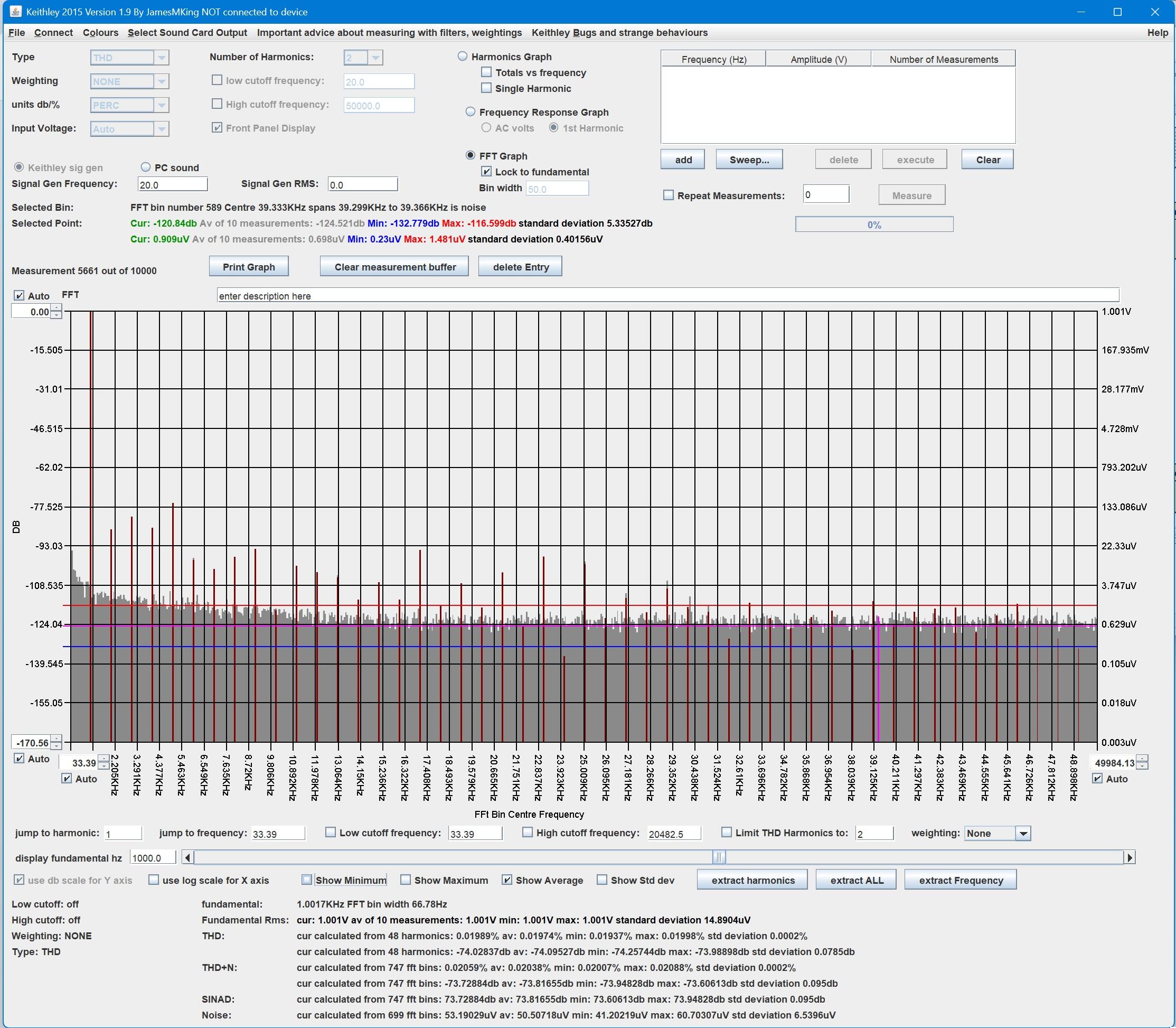
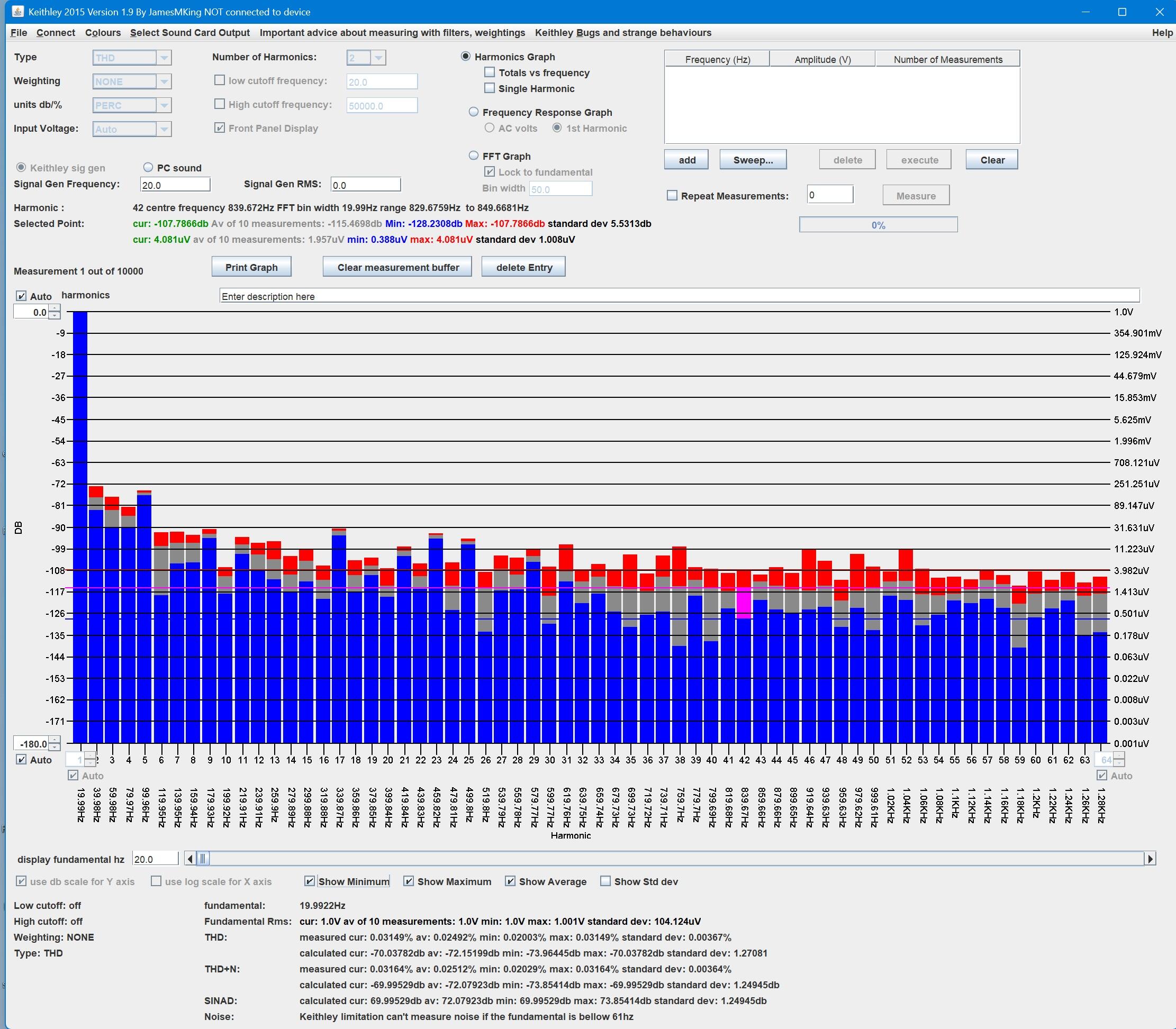
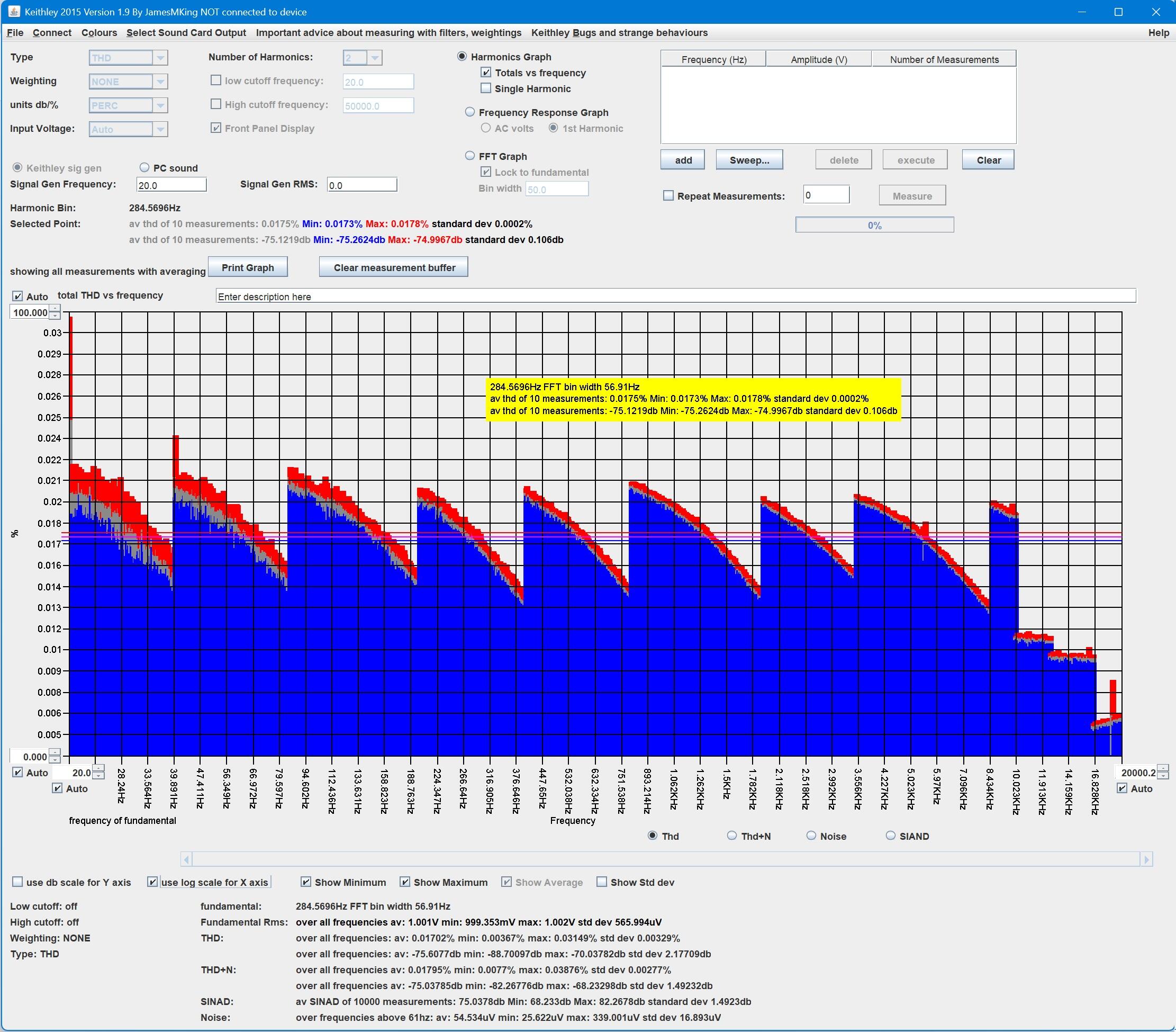
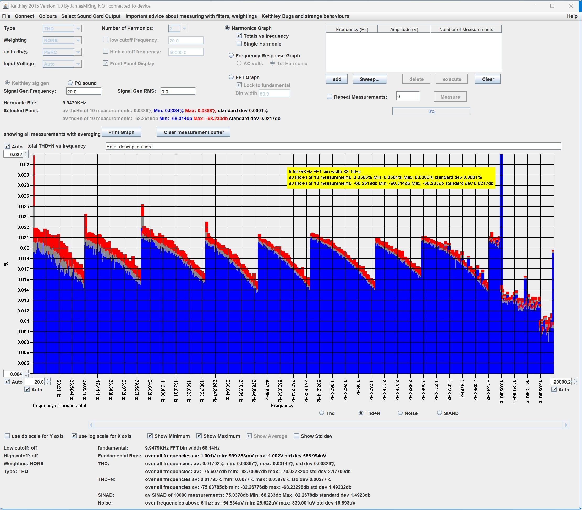
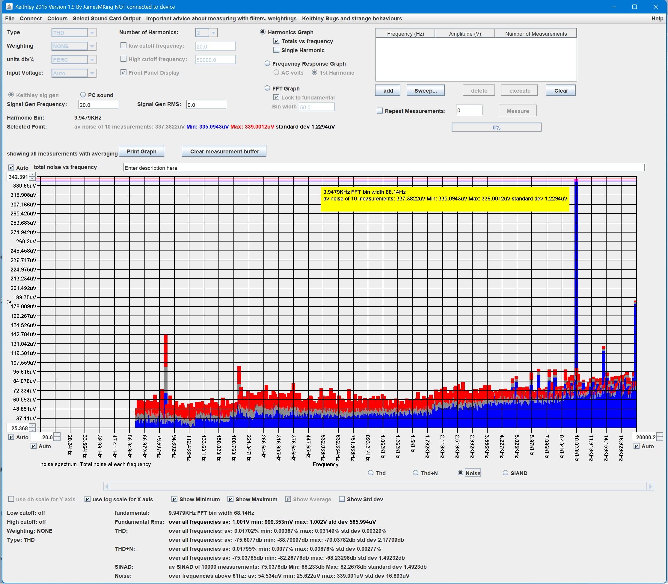
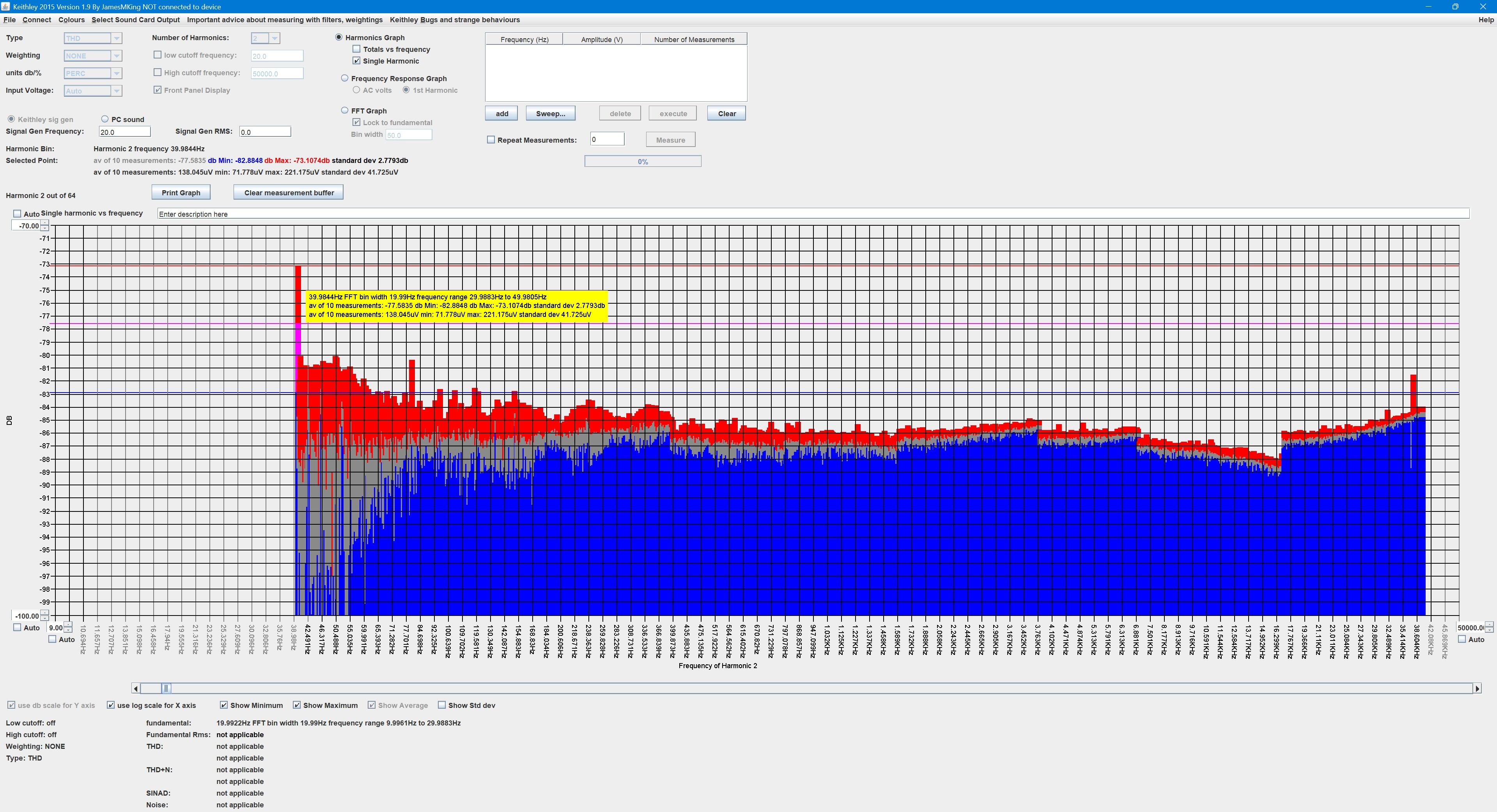
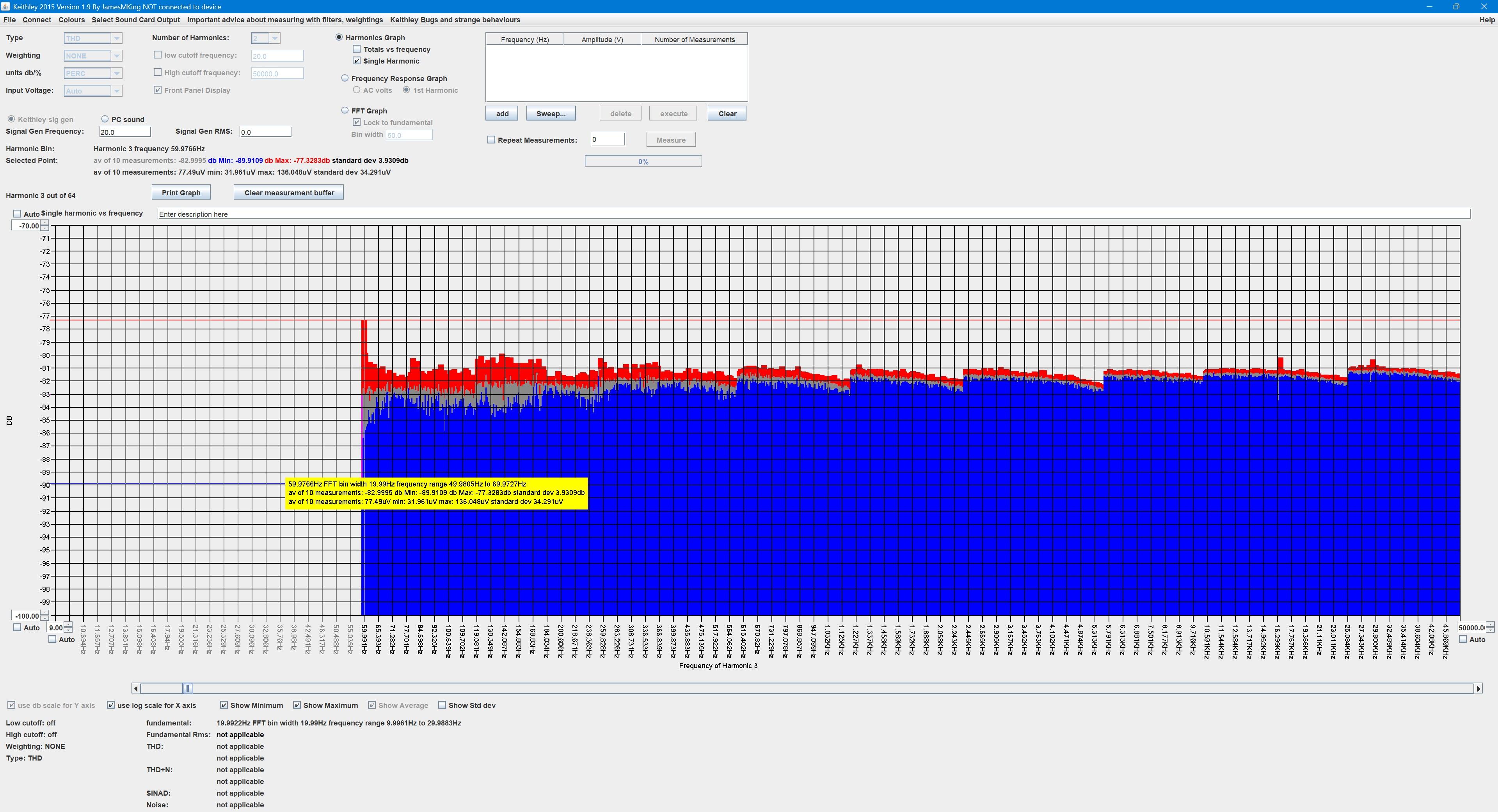
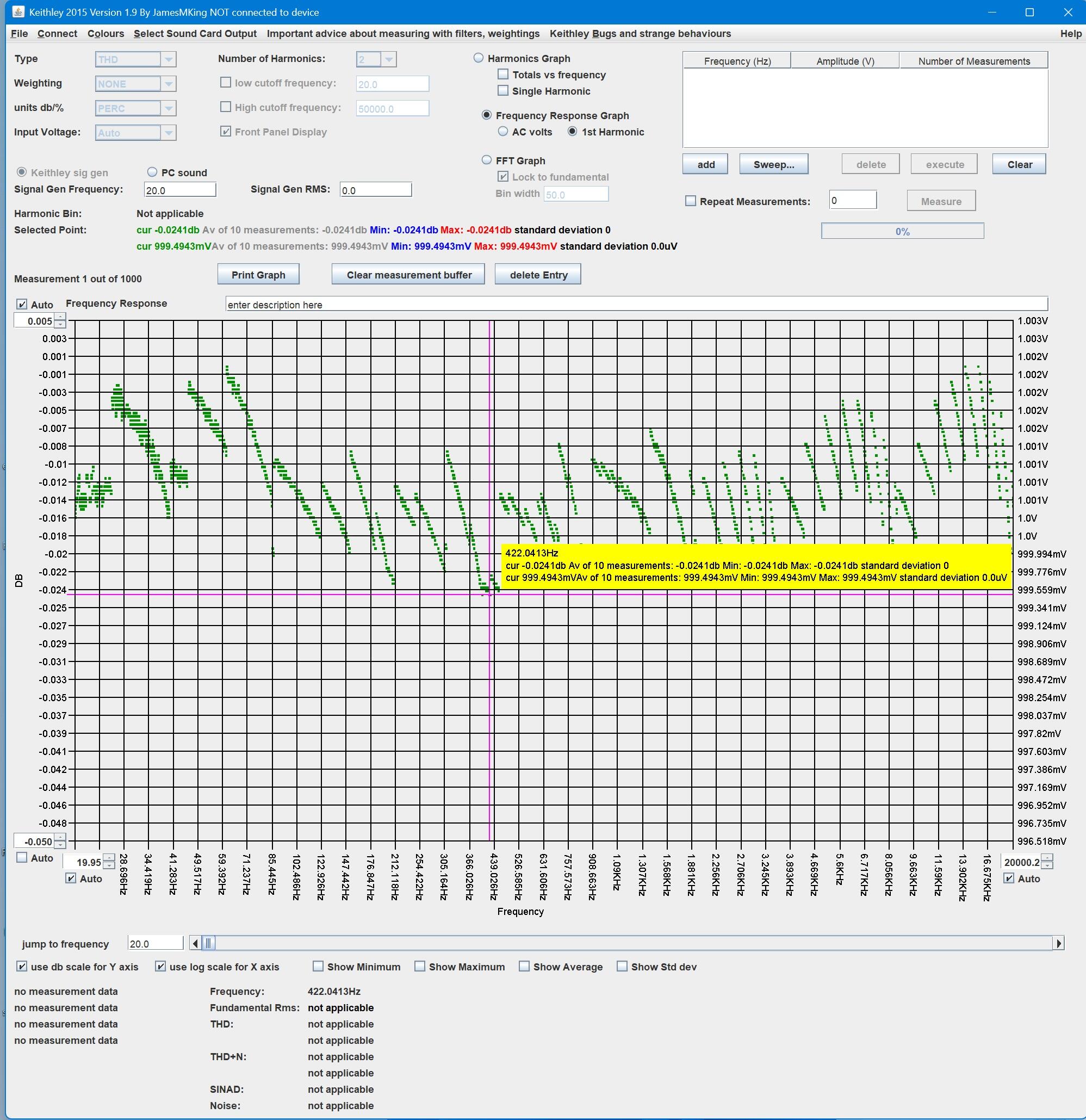
In my opinion the current prices on ebay for a Keithley 2015thd are rather high. To note, the more modern version of my software only supports the National instruments gpib to usb adapter rather than the hp 82357b. This is because I could never get the 64bit drivers to work with the Chinese fake 82357b whereas the Chinese fake national instruments adapters work fine with 64bits (my 82357b also died and i replaced it with the ni and so could not test the hp anymore). If you don't want to get a gpib adapter, rs232 is also supported - its slower to transfer the data from the Keithley to the software (around 2 to 4 times slower but you only really notice this on long transfers such as full ffts or on automatically repeated measurements) once the transfer is complete the software performance is the same. the software has been written and tested under windows. theoretically it could run or be adapted to run on Linux or mac since it is written in java - but I have no interest in spending time on that. Some of the Keithley's more interesting features are only available via gpib/rs232 and the programming guide has multiple errors and omissions and does not in some cases give vital information which means figuring out simple things like how wide in Hz a FFT bin is, is a real pain in the **** - and the width varies with the fundamental frequency in non-linear way. Keithley provide no software or programming libraries and so you are left on your own. You can't even get the frequency of a bin or ask for the bin at a certain frequency on the 2025/6thd (you can on the (2015/6P) which seems crazy. The user interface on the keithley is not that intuitive. Due to some (I assume) design/cost limitations it only has as a maximum of 1023 fft bins which limits its resolution and for fundamental frequencies less than 60hz it can't differentiate noise from distortion since the bin width is the exactly the same as the fundamental, i.e. EVERY bin contains distortion and there are no noise bins. Despite this it will give you a thd+n result for a fundamental of 50hz with no warning that its actually a thd without n calculation! If you set the keithley up with filters or limit the number of harmonics the keithley can not provide unfiltered results. i.e. it only shows on screen and passes to a program the filtered results. There is no way to get at the raw readings. So from a programming point of view its often better to do a full fft and the calculate the thd, thd+n, sinad, noise and apply filters in software than rely on the keithley to do it. On the thd version the fft automatically locks onto the highest bin as the fundamental and if there are two highest bins this causes issues. The fft on the thd has no reliable way for you to manually specify the fundamental frequency, there is a hack but you can only specify a sub multiple of the fundamental frequency in the range 20-68hz and even then the fft is not as clean as automatically locking. The harmonic calculation is limited to a maximum of 64 harmonics regardless of how many harmonics are present in the fft. there are also some firmware bugs (at least in the firmware I have) and there seems to be no reasonable way to get new firmware. The built in signal generator only goes from 10hz to 20K and has a surprising amount of jitter and at 20 hz it can output 19.Xhz which causes issues. The thd/thd+n and sinad only accept fundamentals from 20hz to 20K and at 20Khz there is only the fundamental and 1 harmonic since the fft is hard bandwidth limited to 50khz. Noise calculations are limited to fundamentals in the 60hz-20K range. In short the Keithley shows its age and requires a lot of programming and reverse engineering to understand what's actually going on under the hood. The 2015P and 2016P remove many of the programming limitations of the 2015/6thd and it would be interesting to know if a thd could be upgraded to a P model - it might only be a firmware change since the thd programmatically seems to be a gimped P with certainly very useful programming features missing. Unfortunately the P models are double the price of the thd... Here are a couple of measurements of the Keithley's signal generator feed back directly into its inputs. At least on my unit, the generator has around 0.02% THD at 1V rms output (using single ended - not balanced). Using a good PC sound card instead the thd can be cut by around a factor of around 5-10. So the measurement of the keithley is more capable than the built in signal generator.. Signal generator harmonics at 20Hz (10 averages minimum and maximum values also shown) Signal generator noise and harmonics at 1Khz (10 averages) signal generator THD vs frequency of its output (averages of 10 measurements, minimum and maximum shown note log scale for x axis frequency) Notice how there is considerably more THD at 20hz... this is because when 20Hz is requested the output of the signal generator is actually 19.X and this causes issues with the fft lock on the Keithley. Noise of the keithley signal generator vs frequency of its output (10 averages min and max shown log scale for frequency) notice the rising noise as frequency increases but there is a huge noise spike at 9.95Khz and smaller spikes at 85hz, and 19.86Khz. I have not put any effort into determining if this is caused by the measurement side of the Keithley, external noise or the Keithley signal generator. THD+N of course shows the issues with 19.zHz locking and the noise spikes: here is a graph of just the second harmonic from the signal generator. again 10 averages min and max shows log scale for frequency. notice the large variations between minimum and maximum at low frequencies. These variations decrease with increasing 2 harmonic frequency. Third harmonic is cleaner but still shows the effects of the 19.9hz lock on issue and the trend for the variation between minimum and maximum measurements to decrease as the harmonic frequency increases. frequency response of the signal generator is reasonably flat at +0.0db to -0.024db at 420Hz.


-
personally I set my vpn tunnel location to the USA and then I can see the images... at least until the uk makes vpn tunnels illegal...
-
happy birthday
-
yes ecc88, e88cc and 6922 can all be used. I believe the e88cc is similar to a 6922 - which is what I have been using in the T2 for years.
-
My anti virus subscription includes a VPN. Never needed (or used it) until the UK did the online "safety" act. access via VPN with IP location set to USA works fine for me in the UK... I'm just waiting for the UK to ban VPNs, strong encryption and storing anything locally - after all if you have nothing to hide you shouldn't be worried about the security forces, AI or anything looking at everything all the time... Of course politicians, Royalty, celebrities and rich people will exempt from the this.
-
on the golden reference HV you need enough voltage across the 5.1ohm 5W current sense resistor (R11 on the positive rail) to activate the current limit. *If* I remember correctly the stock 5.1 Ohm gives about 90mA and 2.6ohm (two 5.1ohms in parallel) gives about 175mA. V(drop)=IR so you are looking at about 0.09A*5.1Ohm = ~0.46V to activate the current limiter so V/I = R 0.46V/your required current in A = current senses resistor in ohms. This resistor value will probably need some fine tuning and you ideally want to use a 5W part rated for high voltage.
-
Thank you for making my day less boring and answering my question. I will label you as a troll and a psychopath.
-
for me that's the entire heart of the matter. I want maximum pleasure from music and if the devices giving me maximum pleasure don't measure fantastically I don't care. If they do measure well that's fine by me too. That's my hearing and that's what I optimise my hifi for.
-
"So I will ask again, because no one has dared to answer it: Can a design with objectively flawless data be dismissed as 'crap' based on an outdated topological label?" <-------you unilaterally decide that the topological label is outdated have you considered that I (I almost put we but I don't want to put words into others mouths) do not accept this premise. Unless you wish to be flexible in a debate and have a little bit of an open mind (and a good helping of respect) debate is meaningless. no design is "objectively flawless" this highlights your black and white thinking with zero nuance. Surely objective flawless would be 0% THD infinite frequency response etc. this is obviously impossible. So again I reject you impossible premises. "Who started this by calling a product they hadn't measured 'crap'" < ---I DID NOT "Who, after failing to debate, issued a threat: 'This is your only warning'? " <--- I DID NOT and you decided you won the debate. I don't believe you have but you obviously have a strong desire to win at any cost under your imposed rules and premises and if they are not fully accepted you think you win by default. "Who just used the term 'cheap plonk' in a passive-aggressive insult against other people's choices?" <----- I DID NOT I did not mention the word cheap. I said PLONK - plonk can be expensive I used to it refer to something that the drinking find of low quality - in other words I acknowledge the drinkers choices and they get to decide what they consider to be plonk. threats?? what threats? when have I threatened you? (perhaps I might be threatening your ego) "It was you lot" <- again your black and white attitude that all the people other than you in the debate are the same. lack of nuance. "play the innocent victim" <- how have i attempted to play the innocent victim? I entered the debate with a rough idea of the direction it was heading and I was proven correct. You language and insults have progressively increased (I assume because we are not insulting you back and that's what you deeply want inside to fight physiologically injure us and for you to win. You proudly proclaim you have already won, I think the others in this "debate" may not quite see it your way - and maybe that's the entire problem here. Can you accept that others can have valid views different from your own?). At every step I have tried to debate and you insult rather than debate, or perhaps insulting is your debating style? I cant speak for others but I am not made angry by your words just saddened. I also question if you have a place in this forum, but its not my place to decide and I have not reported you to the moderators (this is NOT a threat its a fact). "We're obviously happy as we are," <--- I did not say this but bare in mind this forum makes no money from membership and (in my opinion) is a fairly close nit community of (mostly) like minded individuals. There are debates and arguments from time to time but usually this is amongst people who have been here a while and at least got to know each other a bit and have some respect for each other and some tolerance. tolerance is something you seem to lack along with reflectivity. I can't decide if you are a troll, deeply troubled or a psychopath. Ether way I wish you well and hope one day you discover the grey between the extremes and learn that you don't have to win every debate because sometimes the debate/journey is more important. regards James P.S. ultimately you might also want to ask your self why did you join this forum?
-
I like lost causes.
-
I see no personal attacks here other than the one you just launched on us. My (guess) is that for you everything is black and white, for or against, with or enemy and that's simply not how things work (in my experience) and that's why debate is so interesting because it can some times bring out the grey and the in between. you talk about debate? I have tried to debate and you retort with insults. that's not a debate. There is an old saying along the lines of the first one to resort to violence in a disagreement admits they are wrong. My take on this is that the first one to resort to insults in a debate can't handle some self examination and I think it would do you a lot of good to spend some time being self reflective and consider the impression you have just made today.
-
My personal take is that it is measurement vs subjectivity is never as simple as belief in one other at the exclusion of the other. Both have their place. I play records and get immense enjoyment from them but would any record playing system measure on an Audio Precision APx555 better than a cheap cd player. No way. Does that mean I reject ALL measurements NO. Will an amp sound good that has 100% measured THD+N and a signal to noise ratio of 0db no way, although plenty of electric guitar amps aim for large amounts of distortion to sound "good". Can replay system with a +3% THD+N give me listening pleasure (which for me is what hifi is all about) - for me yes. Will an amp with 0.001% THD+N sound better than one with 0.01% THD+N? Not necessarily. You need to at the topology, the power supplies, the inter stage coupling, operating points, drive capability etc. This can give more clues. There are some "rules of thumb" that have been gathered over time and with experience and with some (general) consensus. For example unregulated high voltage power supplies on a Stax amp - is going to compromise sound. Use a load resistor (like most of Stax amps do) to the output valves plate instead of a constant current source is going compromise the sound. Drive Stax sr007 headphones with tiny small signal tubes as output drivers? going to sound bad. No output current limit resistors - NOT safe. -580V output bias going to attract dust into the headphones instead of repel the dust. As a rule of thumb class A better than AB better than B better than D (when efficiency is not required). So if you can drink fine wine class A and its achievable and affordable why drink plonk class B?
-
Do you truly believe, all other things being equal that class B will sound better than class A? In the world of amplification for speakers class AB, B or even class D is tolerated because its more efficient than class A and at high output powers pure class A is often impractical, and prohibitively expensive. For headphone amplification efficiency is not an issue given the tiny output power required - which makes pure class A very practical. Because of this there are few reasons to design anything other than class A headphones amps (portable headphones amps excluded because efficiency and power consumption matter here). Kevin Gilmore has designed and helped us build many fantastic Stax amps, for example the blue hawaii (which several companies sell), and of course the T2. He is incredibly experienced and is generous enough to open source his designs AND support those who build them. I would strongly think again about criticising his competence.
-
You could measure the gain. input say a 1KHz sine wave at 250mV, Measure the output it should be about 250V with the volume all the way up...
-
As far as I know most of Kevin's valve and value/transistor hybrids aim for a gain of 1000x - thats what the mostly modern T2 has and I think the blue BJT blue Hawaii. The only exception I have experienced is the (standard) EL34 Megatron which has lower gain.
-
for my megatron build (which uses a 300V golden reference hv psu rail) I used 250VAC which gives peaks of about 350V with nominal AC mains voltage.
-
be careful, the ssth512 has an insulated body and no live tab. The DSEP12-12 has a live metal tab and will have very high voltages on it.
-
the problems with the stax srm006t is that like the srm007 it has too many design compromises that massively effect the sound. 1. its high voltages are not well regulated 2. it uses resistors as a anode load for the valves which reduces current drive and efficiency rather than using a constant current source. (the srm007t is exactly the same design but parallels up the values to get a bit more drive but its still not fixing the problem and costs twice as much) 3. it uses values which don't have much current drive or are that high voltage. Most of the good designs use far more powerful values such as EL34 running at conservative currents (for what they can do) rather than running tubes design for pre amps really hard. The result of this poor bass, poor dynamics, mushy and in general, a sound that, as you turn the volume up the bass gets more soggy but not that much louder. The drive situation gets far worse if you use a difficult to drive headphone like the sr007 (I tried this and you cant get even close to the performance the 007s can provide with a well designed energizer. Replacing a silicon diode bridge with Schottky diodes might give you a bit less switching noise and slightly lower voltage loss but its not addressing the major design issues. If you really want to upgrade the energizer get the anode resistors replaced with a constant current source. This massively increases the drive and addresses some of the poor design of the energizer. If you are in to diy electronics and want to build your own energizer there are a variety of energizers so much better than the srm006 or srm007. one of the simple and fairly cheap options, with better valves and fully regulated high voltage power supplies is the alpha centauri from http://www.high-amp.de. Its relatively simple to build and walks over and kicks in the head the srm006t. I am speaking from experience here. I started with a 006 and built the centauri. The published design still uses resistors for the anode load but the website does offer pre built constant current sources for it. Unfortunately the schematics and the pcb files are not available for the constant current sources. Next come the energizers with constant current anode sources, fully regulated high voltages and beefy output valves: The blue hawai, it will cost more to build than the alpha centauri, is bigger and more complex but sounds even better At the apex of stax energizers is the diy T2. The original one uses transistors which are no longer available and so getting non fake transistors for it is not easy or cheap. The design has been updated to use more modern transistors. I built the mostly modern version which has a mix of old and current production transistors. It big, complex and fairly expensive to build but the performance is fantastic. I replaced by blue hawaii with it and never went back. There is also a mini T2 which is a simplified version using modern transistors and smd (surface mount components). Its not as good as the full T2 but I think its better than the blue hawaii. if you want something that is fairly simple and will warm up a room on cold nights then there is the megatron. I never got around to finishing my build but its one of the more simple designs. There are many more diy designs out there and in this forum. But the bottom line is if you want a realy good energizer for your Stax headphones, Stax does not sell one and most of the other commercial designs are almost equally as bad (and in some cases worse). P.S. the offset or balance DC voltages being a few volts out or drifting around by a few volts is not going to effect the sound or reliability. Remember the headphones are designed to take 100s of volts, 5V or 10V of DC offset or DC balance is nothing to them.
-
22ohm to ground on the heater/filament looks like its there to stop the heater floating and might reduce hum and is therefore probably optional. It looks like this resistor is not present in the megatronpowersupply300v2xl gerbers. It also looks like there is a 221 ohm resistor between the anode and G2 of the el84 in the gerbers which is not present in the megatronps300.pdf. I am afraid I did not build this power supply so I can't comment on which is the more up to date or preferred version. But in general its the Gerbers which people get pcbs made from and therefore is assumed to be correctly functioning unless the threads on headcase say otherwise.
-
you might want to try stereo: Gunter Wand;Ndr Symphony Orchestra (specialist in Germanic symphonies c.f brahms, bruckner) herbert blomstedt;Gewandhausorchester Leipzig Staatskapelle Dresden;herbert blomstedt André Cluytens;Berliner Philharmoniker igor Markevitch;Orchestre des Concerts Lamoureux mono: erich kleiber;vienna po (dad of carlos kleiber) felix Weingartner;london so (first complete recorded beethoven symphony cycle) paul van kempen;berlin po (conductor of kempff classic 1950s beethoven piano concerto cycle) The marmite option: if you like "period instruments historically informed": roger norrington;london classical players
-
Electrolytic caps are well known for being relatively fragile. Almost any reverse polarity voltage will damage them over time. They also degrade with temperature and time too. The input caps take the highest hammering because of the higher input AC voltage peaks compared to the output caps - (which only have to handle well regulated DC). Check if the diodes in the bridge rectifier are leaking, if one of the diodes starts to leak more than a couple of volts that would degrade your input cap. Also, when you have got the amp up and running again it might be worth monitoring the temperatures close to the caps, a rough rule of thumb is every 10C degrees rise in temperature halves the cap life. I have had good reliability experiences with kemet al10 series caps - although they can be expensive they are rated at around 15000 hours at 85C - significantly higher life expectancy than your caps and life expectancy. Part number ALC10A681EL550 is 550V 680uF. The ripple current of the kemet is 50% higher than your caps, but the esr of the kemets is higher, leakage current is the same. Unfortunately kemets tend to go in and out of stock again and the pricing can also be somewhat erratic. note the ALc10 kemets tend to be tall rather than wide - the ALC10A681EL550 is 80mm tall and so you would have trouble fitting it into a 2U high case.
-
farnell in the uk has plenty of stock of the FJPF2145 https://uk.farnell.com/onsemi/fjpf2145tu/trans-npn-800v-5a-125deg-c-40w/dp/3368628
-
FJPF5027OTU seems to be a possibility, seems to have similar specs except lower current rating and the same pinout. Hfe of FJPF2145 is 20 - 40 which is the same as the O variant of the 5027
-
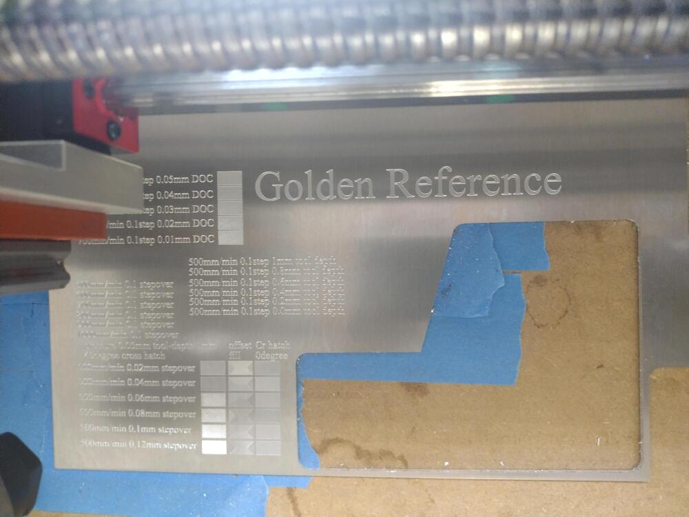
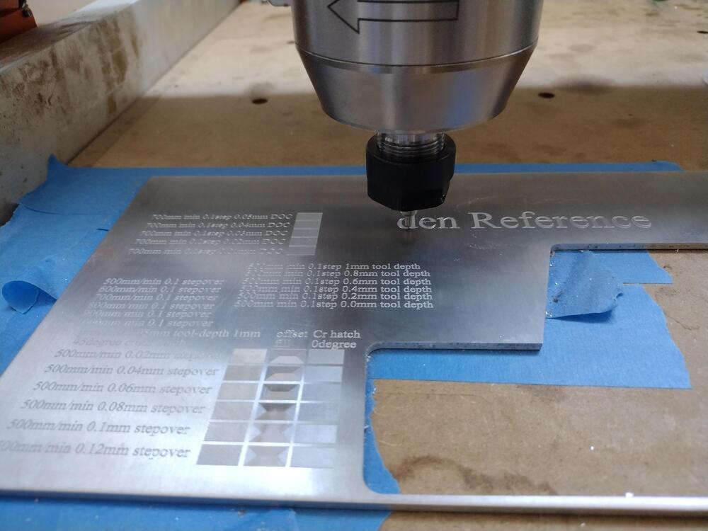
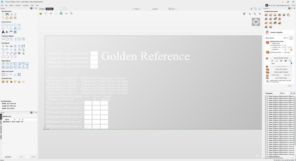
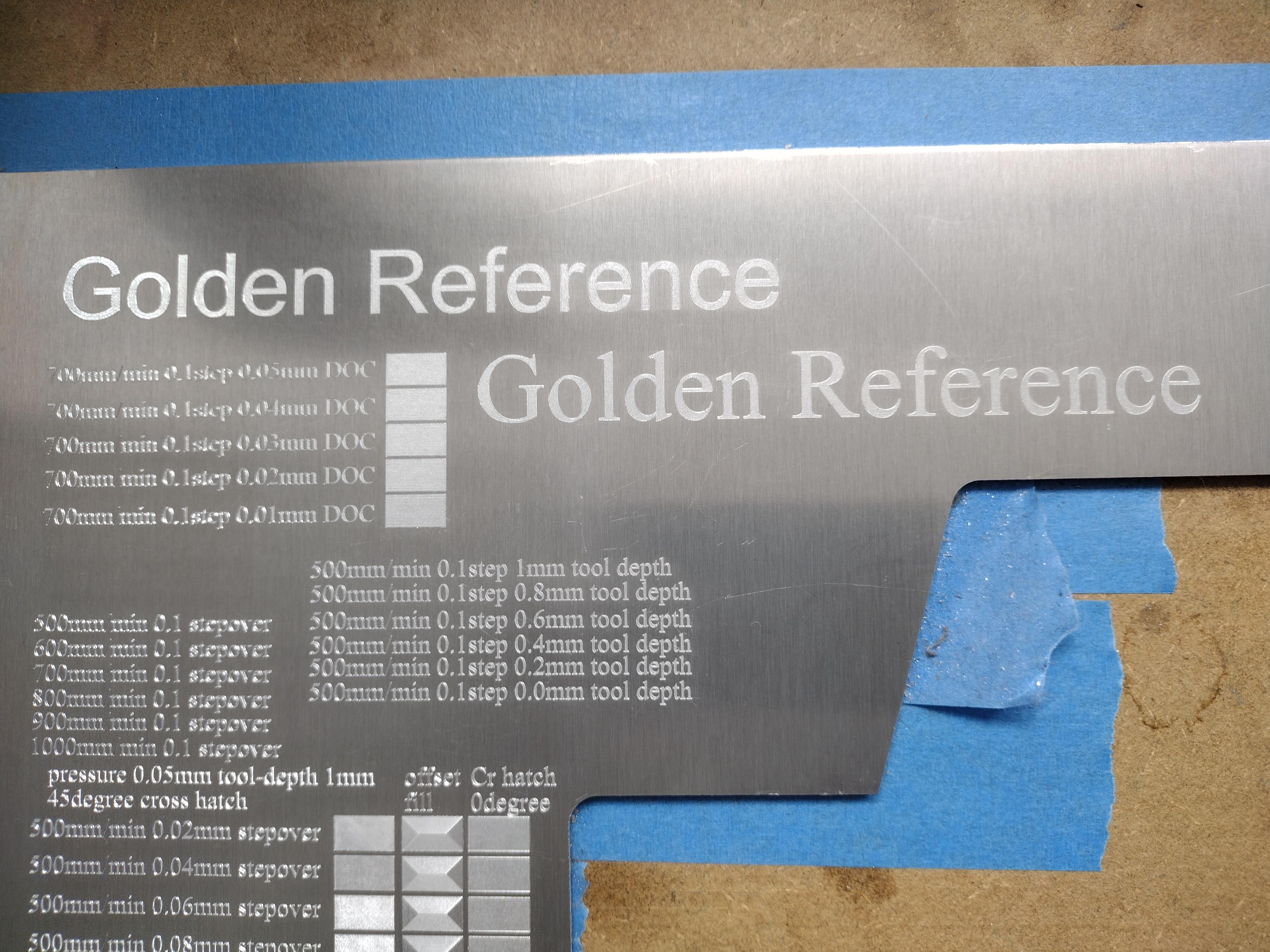
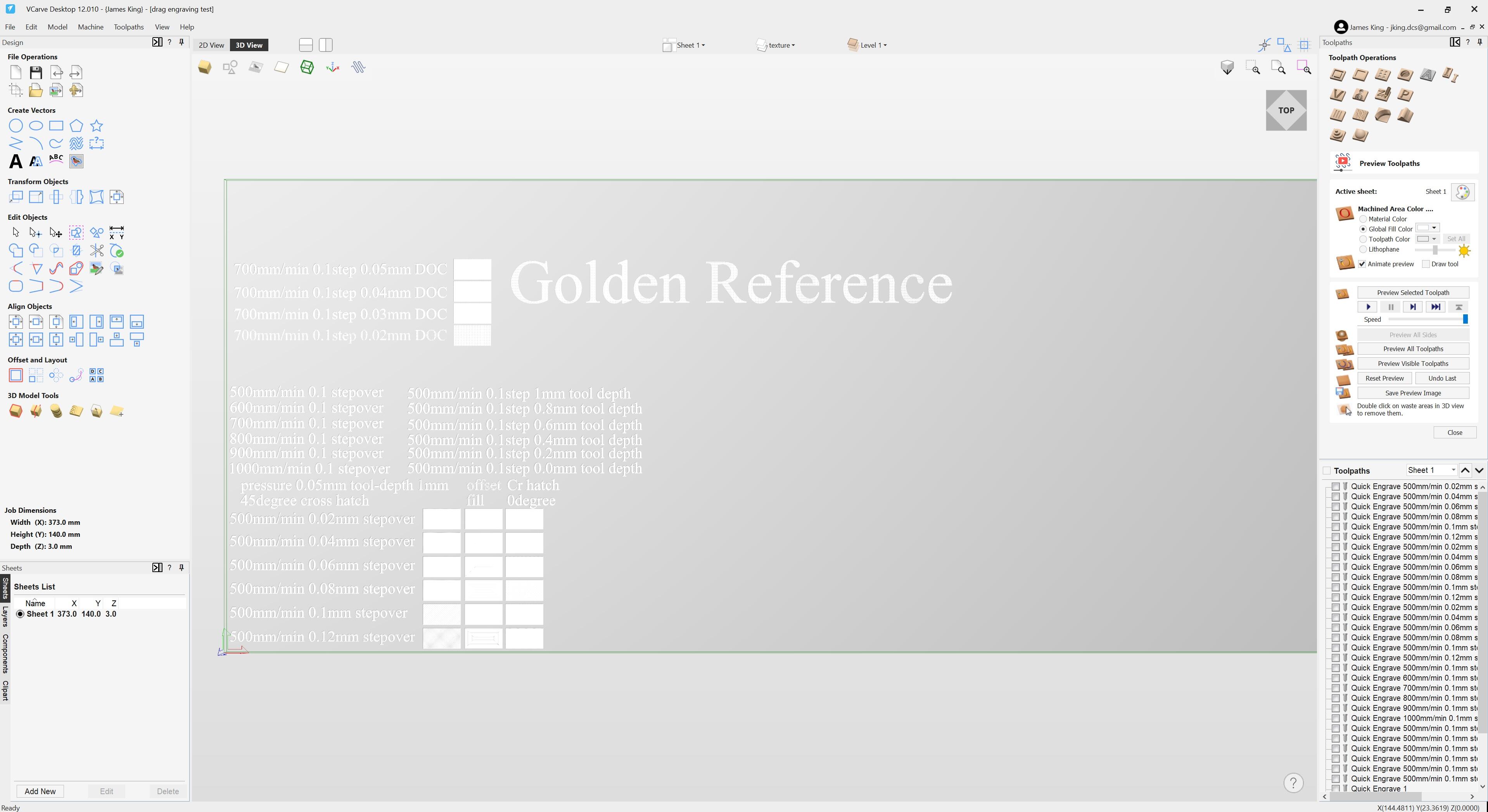
Diamond drag engraving is surprisingly fun and easy. I decided to buy a spring loaded diamond drag engraver and do some experimentation on feeds, cutting depth, stepover etc. I ended up. 90 degree drag bit. tip flat estimated at 0.128mm, 0.1mm step over, fill crosshatch at 0 degree, 700mm/min feed speed. Far better results than using a V bit, much less sensitive to the material not being totally flat and far far faster.


Important Information
By using this site, you agree to our Terms of Use.