Kerry
High Rollers
-
Joined
-
Last visited
Everything posted by Kerry
-
Happy Birthday Justin!
-
I don’t ground the PS to the chassis because there is a switch on the amp board that ties ground to the chassis or can leave it floating.
-
That’s great news. Congrats. I just use resistive loads mounted on heat sinks. Make sure they can handle the power and voltage.
-
That will do. Take it from one of the positive rails. while you’re at it, double check the value of R72 and confirm continuity of the ground pin for the reference.
-
^ Agreed
-
Don’t worry about Q16 and Q17 since you are getting about 425v out of the regulator. If you are getting 30v across D12 then it says that Q18 is most likely working. If you report back on that it will be easy to figure out next steps.
-
Possibly Q18, but most likely Q19 or the regulator circuitry itself. You could check the voltage across D12. Should be around 30V.
-
If the -560v is correct, then the 300v supply coming off of it must be the problem. The -560 + 300 voltages gives -260v.
-
-
Having a great time so far. My granddaughter is coming soon. Can’t wait
-
No. The CCS has the potential to exceed the -400V rating of the 1156. Bad things could happen if it does. The batteries might be possible though I don't recommend it. It's cutting it close if something goes wrong or while you are doing the initial adjustment on the batteries. I'm pretty sure Q1, Q2, Q3, Q28 & Q29 are on the heat sinks. I'm confused by your statement above.
-
Back in the day (for various builds) we used 2SA1156 (-400V) and 2SA1486 (-600V) pretty interchangeably provided the voltages were in spec. K2SA1156 is a direct replacement for 2SA1156. I would recommend using K2SA1156 where it works. It is proven and better not to jury-rig something if not needed.
-
At full voltages you can use K2SA1156 (as JoMat suggested) for Q1, Q2, Q3, Q28 & Q29. It's what I've been using in my builds and is a good substitution. I also use STN9360 as a replacement in some areas, but I've redesigned the boards specifically for them. I don't recall which of the remaining 2SA1486 (batteries & CCS) are mounted on the heat sinks, but if they aren't, it seems like you could use 2SA1413 though I never have.
-
-
Condolences to you and your family Todd. Cherish her memory
-
That looks like a bad spec sheet. 2SAxxx transistors are always PNP and 2SCxxx are NPN
-
Happy Birthday Brent!
-
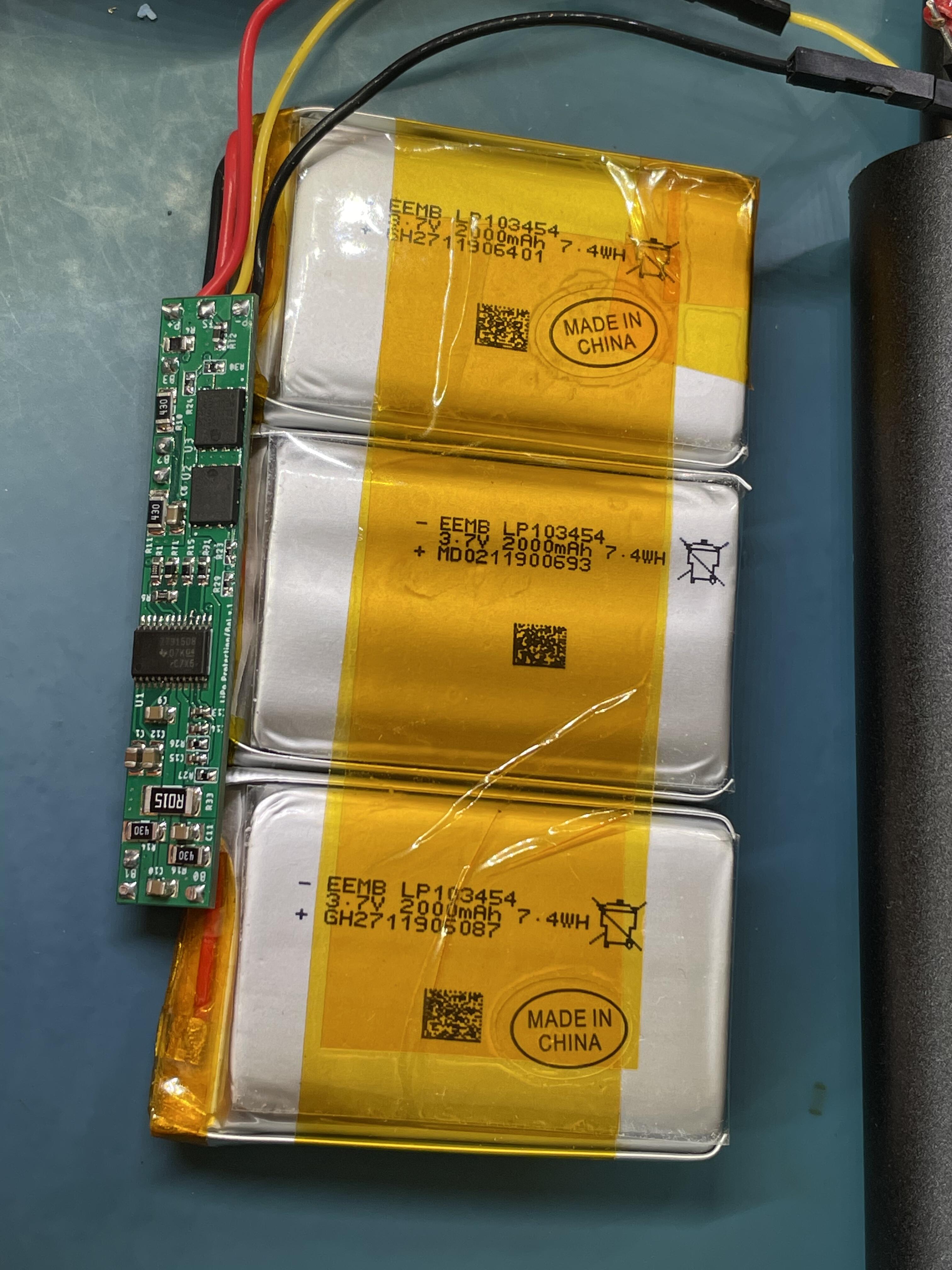
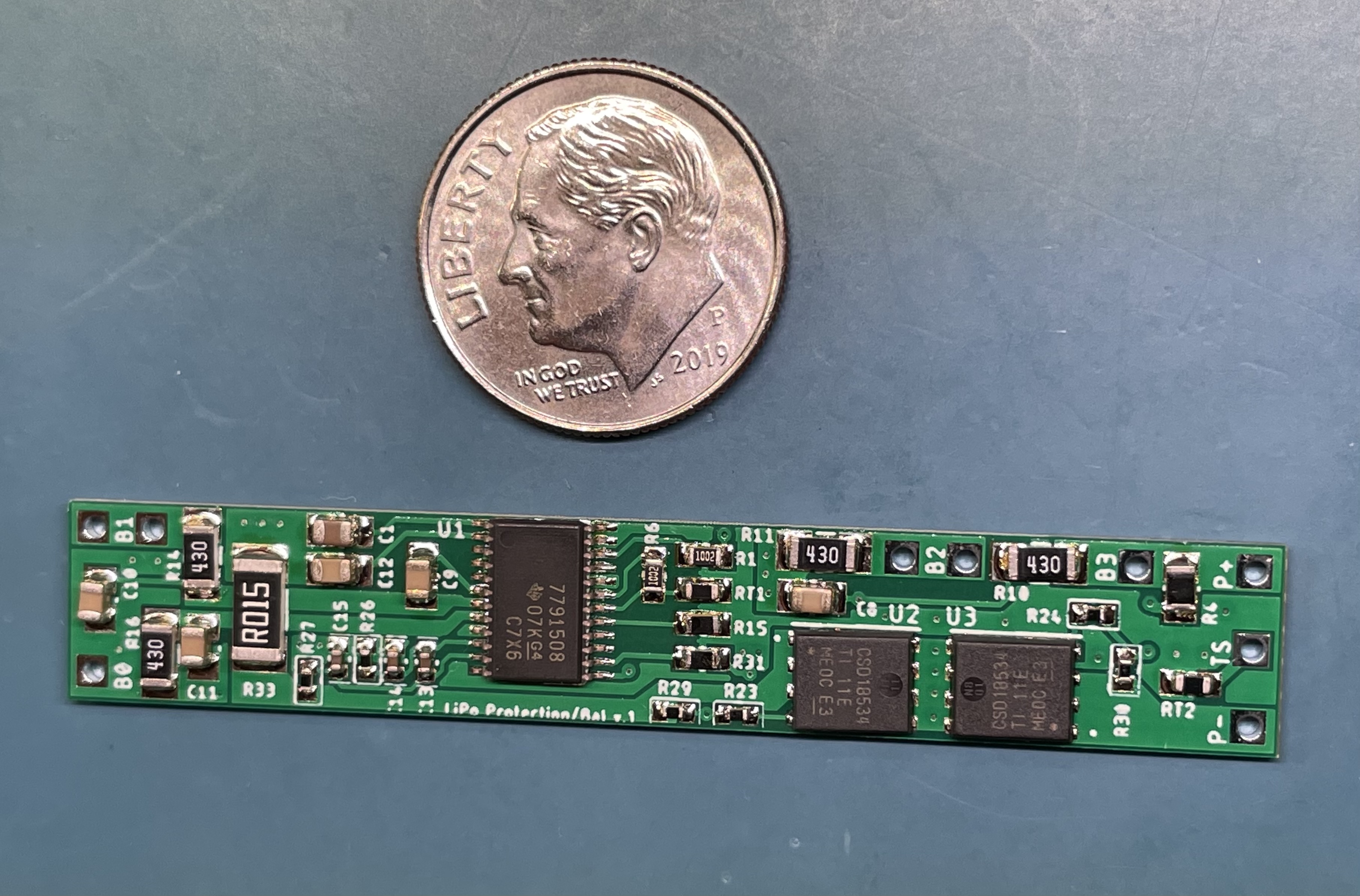
Initial testing on the balancer is looking good. I’ll need more testing to confirm, but the batteries are much closer than before. This should help to extend battery life.

-
-
Here are the part numbers for the 8 pin connectors and pins... 1-794065-0 770579-1 770988-1
-
I got the board and parts in for the battery protection/balancer and was able to get one built. I’ll try to get some testing in tomorrow.

-
Happy Birthday Chris
-
I'm doing a trial on Qobuz just to see the difference. From Roon they look pretty much the same. Metadata, etc. is identical. You can click on Tidal or Qobuz on the left side menu of Roon and they highlight different songs, but that's the only difference I noticed. PS Also, the catalogs are slightly different
-
They are the Phoenix Mate-N-Lok-2 connectors. They are rated at 600V which is nice.
-
They're just Nylon R Type Cable Clamp Fasteners. I got my last batch from Amazon. I tend to use 1/8, 3/16 & 1/4" sizes.