Kerry
High Rollers
-
Joined
-
Last visited
Everything posted by Kerry
-
No rush. I just need one, so let me know when you get back. Thanks
-
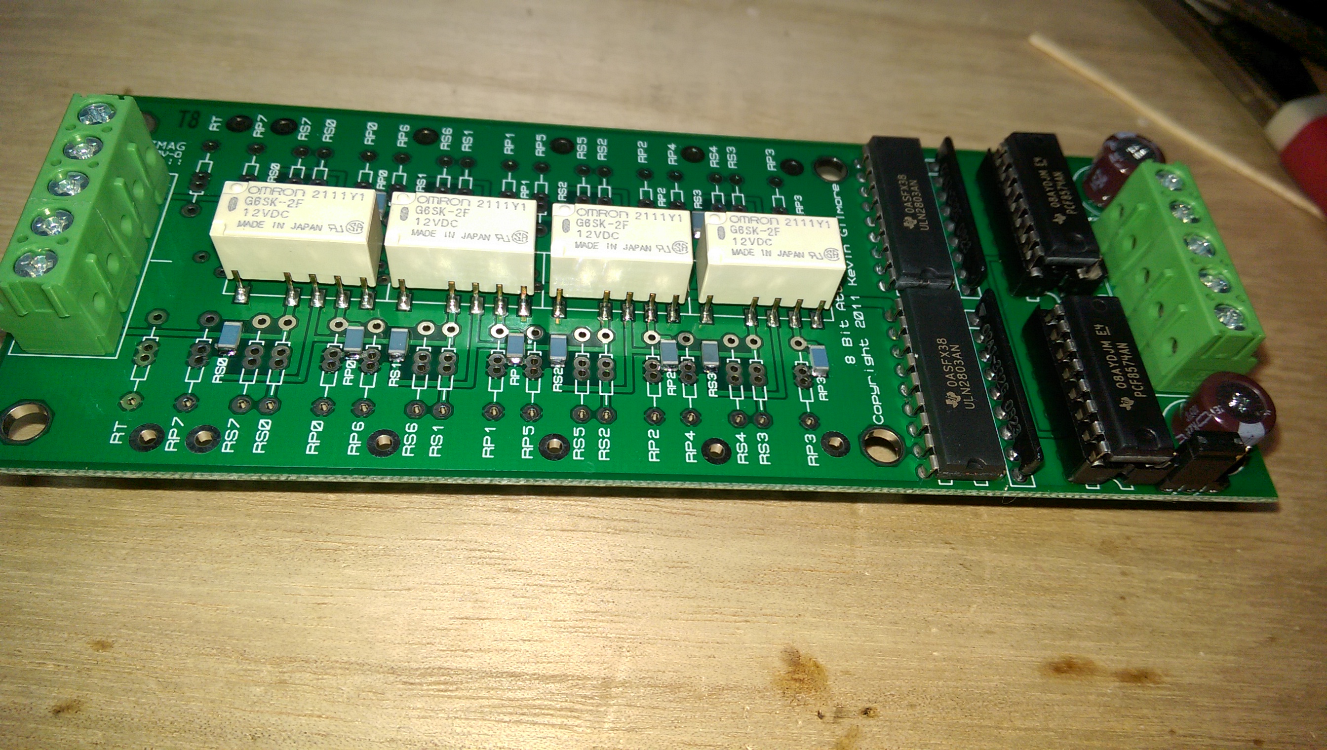
Does anyone have a bare board for the original group buy digital attenuator. I've got parts for another, but no board (not good planning). I wanted to build it so I can test the controller software for balanced operation.

-
Still working to make sure it's stable. I'm very close, just working on the DC issue on the left channel. I went back and replaced Q16 - 20 on the front right battery because the noise was still present, thought I could fiddle with the adjustments to make it go away. The sand replacement has completely fixed this. I'm having an issue where I can't stop listening long enough to look at the electronics
-
I've started on that. I've got a spice model I can you you're interested.
-
For the grhv it is critical to use the 1021 reference since it has alot less noise. On the LV version it is a bit less critical because of the lower multipliers, but still a good idea.
-
@iwiki - Les, Try this version. I made sure the full init sequence was run for the I2C version. Somewhere along the line I accidentally removed this code for I2C, but still had it for the SPI interface. Also, I added code to invert the set / !set for the first four relays based on the layout change for the current group buy boards. You'll need to set line 48 to rev 2.1 instead of 2.0. This needs to be tested and I have not built the current board just yet. I'm also going to support the original group buy boards, but need to spend a bit more time with that. I'd like to add a Bluetooth shield so we can remotely change the volume. We'll need to build an app to support this. I thought to do this with Visual Studio and Xamerin so it will be cross platform for phones.
-
This is great and gives options for using all current/available parts.
-
Craig gave me the idea to start there when he was talking about oscillation due to the feedback lines. I'm not sure if mine is the source of the problem or if I'm just masking something else, but it works perfectly. The feedback paths are fairly symmetrical between the two channels and fairly short runs compared to the original boards, so not sure why this was happening.
-
I use bulkwire.com or McMaster.com I remember Craig had some sources in the UK. I think they were in the T2 thread.
-
I increased the 5pF bypass cap across the 100k feedback resistors to 15pF. I only need this in the right channel. I'm going to work on my DC issue tonight.
-
I'm happy to report that I solved the oscillation issue on the right channel. Things are looking good. Still need to solve for the DC issue in the left channel. The -543 TP is sitting at -507 with the top of both batteries sitting at +233V. The outputs sit properly with the same adjustment on the 510R for the left and right channels. I'm going to change the collars and isolators, just in case there is some leakage there. It's curious that it's pulling both legs up equally. Thoughts? EDIT: I've thought of doing some similar milling of heat sinks John. Looks like a viable solution.
-
-
^this. I have not used stencils yet and do everything by hand. Here's a video that gives the basic idea: Applying solder paste by hand Don't worry if you get some solder paste between pads of the MAX chip. Once you heat it everything will be fine. Chips will center themselves and the paste will flow onto the pads and legs. Only if you too much paste will it create a bridge. If this happens just use a braid and iron. Also, the center pad on the MAX chip is for heat transfer. It's best if is connected, which rules out an iron.
-
The Conrad heat stinks seem to be ground flat and I have not had any issues. In my case since I'm mounting the transistors directly to the sinks, if they are bowed the ceramic isolators would crack when you torque them. I don't do any additional treatment to them.
-
This build was the original inspiration for my mini build. Thanks for always trying new things I do have some oscillation in my build and I'm going to need to jump into that now.
-
Do you have a supplier for these in the US. It's an easy enough thing to do, so I might as well.
-
I'm using the Uno. But it really shouldn't matter. There could be something slightly different about your display. We'll figure it out.
-
I just bought a Nano v3.0 last night so I can try it directly. I should have it by tomorrow. Let me try it and see if there needs to be any tweaking. Also, check your connections. I have SCL to pin A5 and SDA to pin A4 on the Arduino. All I did to the code to get it to compile on 1.6.8 was to add a forward reference to the function SetVolume in the top part of the code. There's a lot I want to clean up in terms of how I want the code structured. This is just to test the boards and make sure they function properly.
-
I typically go with split washers. I used those on Al's build way back when and on most of my other builds. For #4, I did not see spring washers at McMaster.com where I get all of my mechanical doodads. I might look around for another source in the US and give them a try.
-
It's possible. DC was about right, but it could have been a bit leaky. Might have been damaged by an earlier short in this channel. I fixed it by blowing it up completely thus requiring a change.
-
Hi Les, I've been a little focused on the amp build. Just sitting here listening to it now and trying to remember about the code. I just downloaded the latest 1.6.8 version of the IDE. Let me play a bit and see what's going on. My display is working as is, but I know there are a couple of different controller chips used and it's possible yours is different. Take a look at the description of the display. It will likely tell you what the controller chip is. The code is currently set to support the SSD1306, but I also support SH1106. Let me know. EDIT: I just sent some updated code to Kevin to post. EDIT 2: I'm not sure that this will run on a Nano 2.0, but should on 3.0. I've got some large display fonts I'm storing, so probably needs the ATmega328, which is what I've been testing on.
-
Noise issue solved on the right channel I'd like to think I'm brilliant, but in this case purely dumb luck. I changed out one of the K216s coming out of the top of one of the batteries. I needed to do this because of the dumb part of my luck. I do love this power supply Just listening now in all of this the baby's full grandeur Still need to address the DC offset issue in the left channel and there seems to be some HF oscillation in both channels around 739KHz. @iwik I haven't gone through any final torqueing yet. My method is to drill out the transistors using a #26 drill bit and then deburr. This takes away any stress on the washers. I don't see why there would be an issue with bringing these to spec though. I bough a torqueing driver a while back. There are still a number of mechanical steps left on the amp. EDIT: Yes, I'm using the 3PPSG washers.
-
Thanks everyone. I really appreciate the comments. Yes, these are Conrad heat sinks. The PS uses 200mm x 75mm and the amp is using 350mm x 75mm. I'm seeing about 110 deg. F on the heat sinks at the hottest point of the amp. The amp and PS will be identical in size at 12" (W) x 14.27" (L) x 3.33" (H - not including feet).
-
They're just the new Mullard tubes. Nothing fancy yet.
-
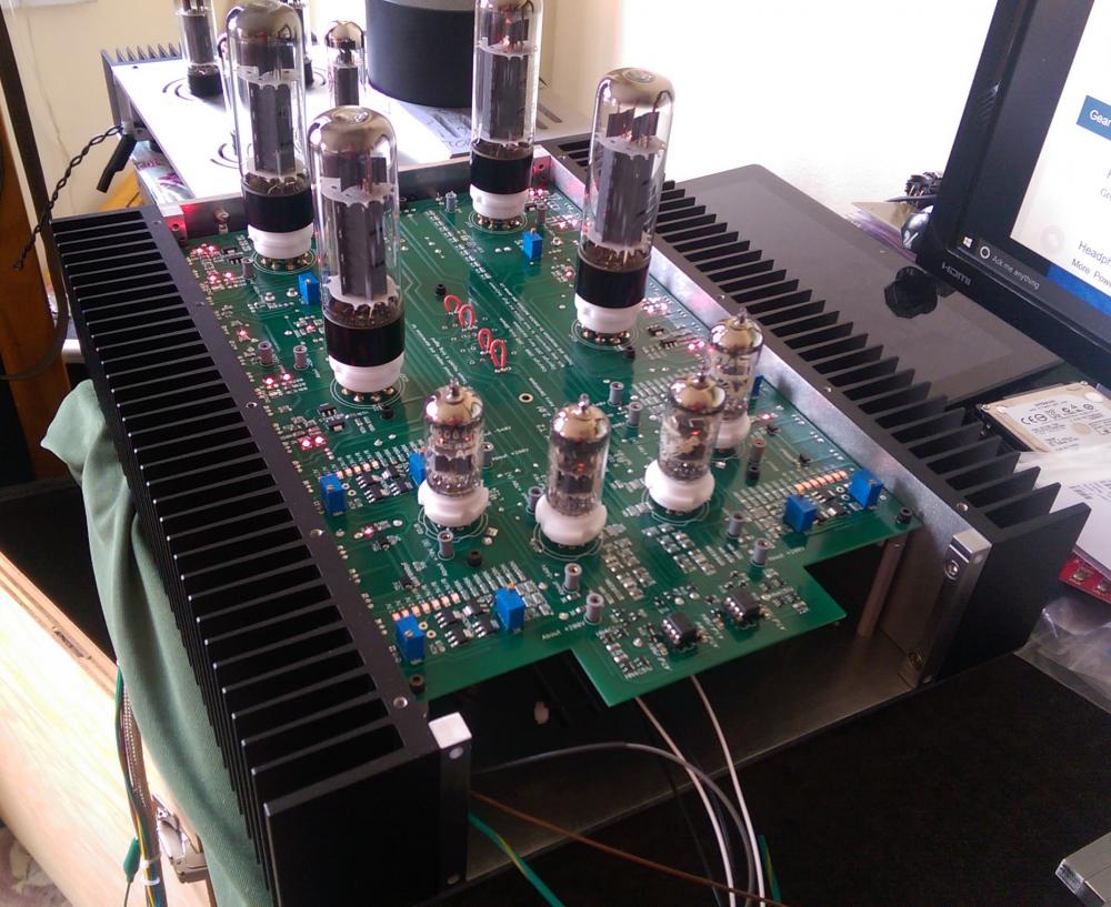
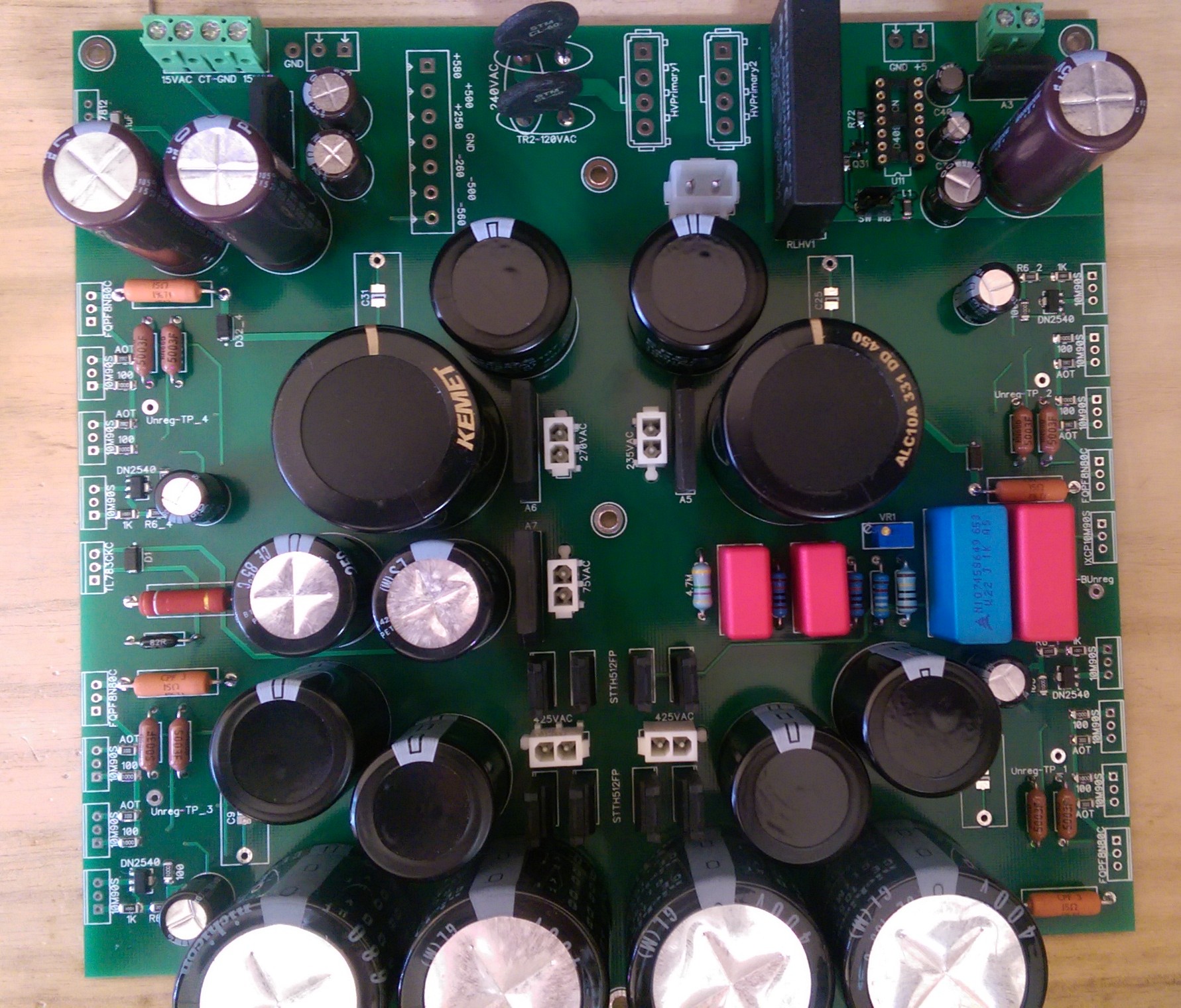
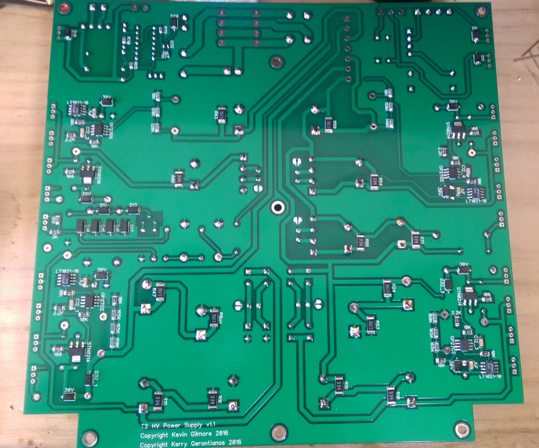
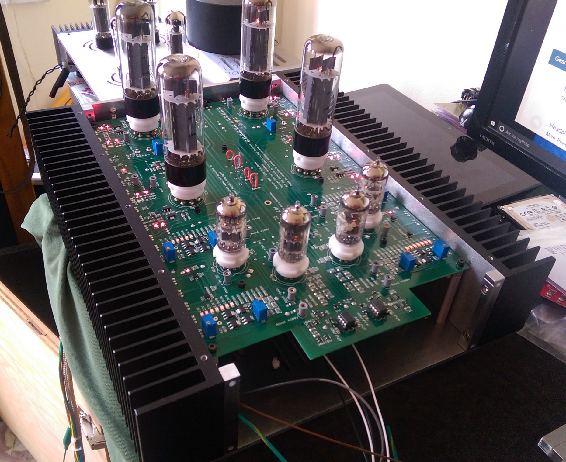
So here's a progress update on my T2 mini build. I started off with the a golden reference version of the T2 supply. Had a couple of issues. There was some 60Hz noise I was hearing (I'm guessing from the integration of the negative rail supplies), which I can probably solve for. Also, the current limiting, which works, wasn't fast enough when there was a shorting issue with the amp on the negative rail (FETs in the output section shorted to the heat sinks). It would pretty much blow out several components in the supply. I decided to go back to the original design, but as a shrunken version (206mm x 200mm). I did some small mods (added cascaded current source for the 30V supply to the opamp and added some additional spots for compensation caps. I finished this over the weekend and have spent some time listening. I've still got to tweak the PS (some small oscillations - probably because I was experimenting with the .1uF cap to the negative input of the op amp and added a .1uF cap across the voltage divider). My BK multi-meter is showing between 1mV and 0 on the AC setting. I've had some of the supplies on the scope but will need to go through all of them. This causes some very faint background noise. The amp has had it's fair share of issues, primarily with the output FETs shorting to the heat sink. I've had this once on the left channel and three times on the right. I believe it was that some thermal compound found it's way inside the collar of the thermal washers (7721-3PPS). I've cleaned these up and have had the amp on for 12 hours now with no issues. Also, the right channel DC test points are all pretty much spot on, but the left channel has an issue with the -543V test point. It is sitting at -502V (the rest of the DC test points are pretty close except for the top of the batteries that sit at +238V). I've been looking at this issue for a while, but haven't figured it out yet. I've got to focus here a bit. Any thoughts would be appreciated. I also have to finesse the battery adjustments to get rid of some occasional noise coming through the right channel as well. I have had my 404's and then later O2's on this beast. Wow, how nice It's been too long...