


Kerry
High Rollers
-
Joined
-
Last visited
Everything posted by Kerry
-
I've had mixed results with SumR. Never something so bad as what Birgir experienced. Mostly noise issues. I got the original T2 transformers from Richard and they worked well. This current batch send to be good as well.
-
I've added an adjustment across the 510R resistor to set the output voltage. This works off the second to last stage, so the tubes really shouldn't change things, though if things vary too much, I suppose it could.
-
I may put in holes to adjust the output offset, though its not really needed given the T2's servo. The batteries, likewise do not need to be adjusted once set. The small input tubes were moved to the front for aesthetic reasons. Since the attenuator needs to sit in the middle of the board (given the size reduction), it doesn't add any distance to the trace runs.
-
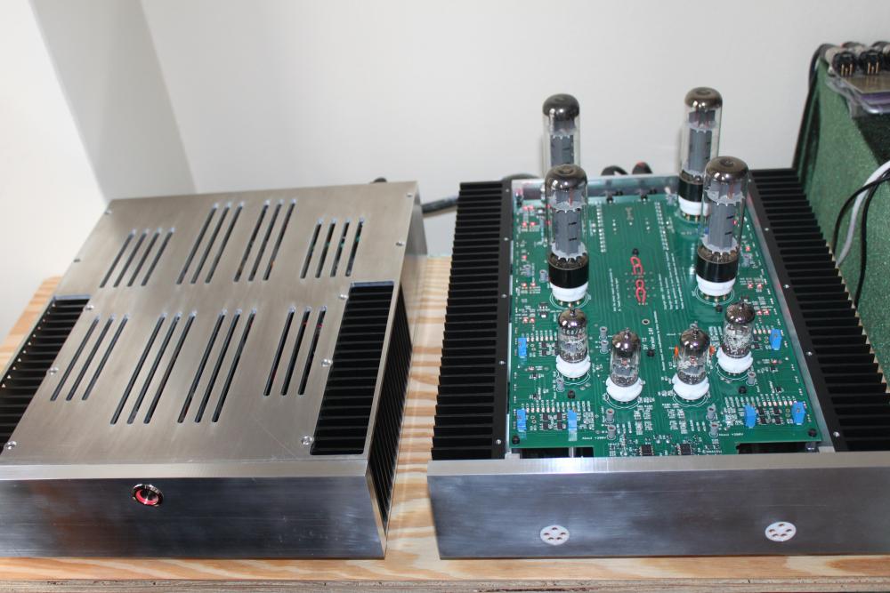
Power supply top plate complete
-
^ Awesome. And I got to see another childhood hero Wilma Rudolf.
-
This was my wedding day. What a headline!
-
Wow... Another icon has passed. RIP Ali
-
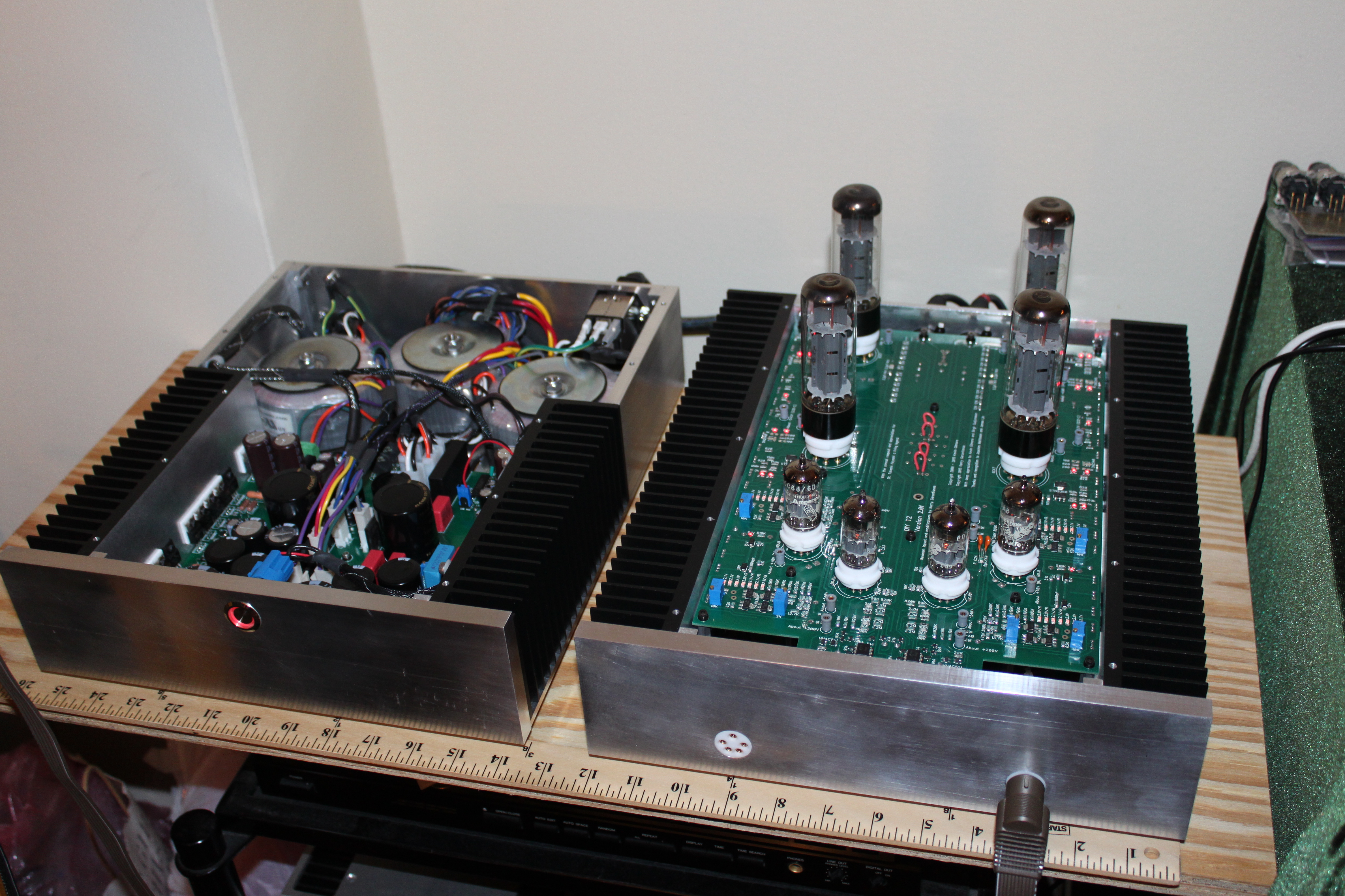
Thanks everyone. Just two more plates to mill and the chassis are done, then off to have them finished The pot will come shortly. I'm going to use an encoder and Kevin's digital attenuator boards.
-
The delay is because you need to get approved for the not-for-profit version. I'm not sure how much faster it is for the regular versions.
-
It's coming together

-
I went through the upgrade recently. I think it took couple of days all in. I like the new version
-
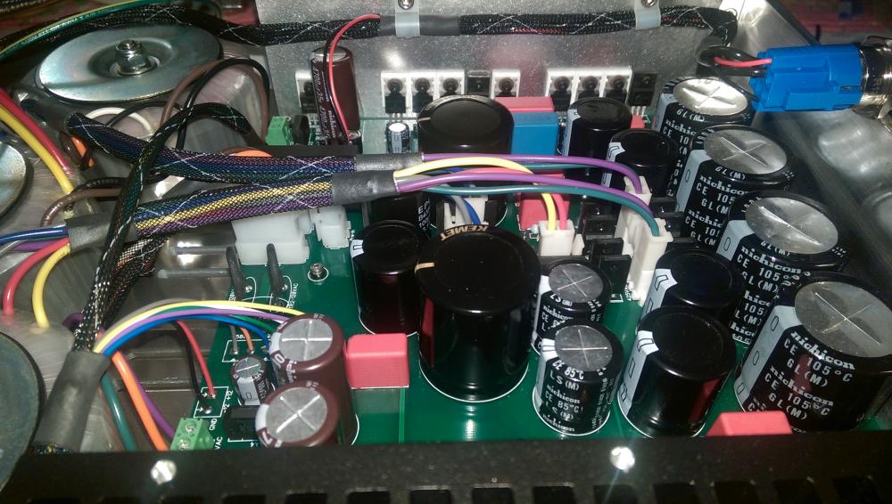
Thanks for the comments above I do appreciate it since I'm always looking to do better. I was thinking of putting the transformers in the front, but I couldn't fit the power inlet and output comfortably with the board layout. I can think about this as a future revision. Currently, I've got about a 4" gap between the top of the transformers and bottom of the inputs when the units are stacked, which helps a bit. I've also got about 2" between the transformer and output and I will shield the output cable leading to the output. Transformers are shielded too. Additionally, I added shielding (tied to chassis/earth on the PS side) between the AC in the umbilical and the DC outputs. I can look into mu metal / steal as well. This seems like a great solution. What about a steel mesh (just thinking of air flow)? What's the specific concern on the transistor mounts? I know there are more screws if I want to remove the board, but I did like the idea of saving space and also that there was one less component between the transistor and the sinks. I considered mounting the transistors to a 3/16" flat plate and mounting the plate to the sinks, but it just felt like a lot of extra machining and I didn't have a clear goal for it in mind. EDIT: One other thought/question. I was going to solder the transformer leads for the filaments directly to the output jack. If I need to replace that transformer for any reason I could simply cut the leads and splice the new transformer in. I don't love this, but it's not that much work in the grand scheme of things just in case the LV transformer blew out in the future. Are there any good suggestions for in-line connectors? For the output filaments, they'd need to be able to handle the -500V to chassis/input filament isolation. This feels like a bit of over-engineering, but this whole build is about that :)
-
The switch was this one: http://www.ebay.com/itm/161443985922
-
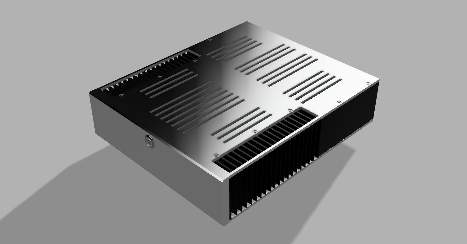
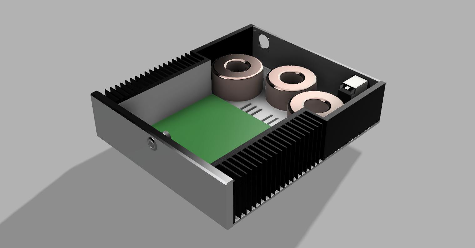
Working on casing the power supply now. The first two images are renders from Fusion 360 (love this program for CAD/CAM)... I got the transformers from Richard at SumR. I added a winding to the LV transformer for the +5V I use for the control circuit/relay as well as the Arduino and digital relay. I also removed a winding on one of the HV transformers since it's not used and adjusted some voltages. Just finished testing them in the new setup and so far so good. I've still got to test everything under load before reconnecting to the amp. The face plate is a temporary while I mill the final one.


.thumb.jpg.522e13581717fa034ec8b3182eeb64cd.jpg)
.thumb.jpg.5246d485eac82e428e6894183e3808e1.jpg)
-
-
Yes. I used my mill for this. My version 2 mill is fairly solid and as long as watch the speeds and feeds, I can mill 1/2" plate no problem.
-
Nicely done!
-
Thanks John. I've always been impressed by your build as well. No, it's for a digital encoder so I can use the new version of the digital attenuator. I have couple of different style encoders that this pocket will accommodate. The attenuator will mount over the board where the POT mounts are. I'll probably make up a board to make this easier.
-
Working on the face plate for the T2. I made the jacks and the boards and milled the face plate out of .5" stock. It's blind mounted from inside the chassis. I'm just about ready to wire this up. EDIT: I also need to add the hole for the POT. I've got a bit more milling to do on the face.
.thumb.jpg.ae9131492ee88ff2936b9e366fd1aae8.jpg)
.thumb.jpg.d7f95a1ca5cf0443ba623cb55e8ea065.jpg)
-
-
I'm glad you found this. Not easy to spot.
-
-
Happy Birthday Ari!!!
-
Thanks
-
Kevin has reposted a new version of the volume controller at the same link as above. It now supports v1.0 (original group buy boards as well). You just need to comment line 104 and uncomment line 105. Again, these all need to be tested before connecting them to an amp to make sure they are properly controlling the relays. If you want to control balanced for version 1.0 boards (two boards), just change the false to true on line 105.


.jpg.3520493ce00038c8102b6833d1336d62.jpg)

.jpg.49acaffc3cdac312ba5e6b3f0608d437.jpg)
.jpg.88dfb6e06d5b0229ee0469b03d757f92.jpg)
.jpg.91742d1b2ff6ef90221a99803ed4fc89.jpg)