Kerry
High Rollers
-
Joined
-
Last visited
Everything posted by Kerry
-
Congrats! You have certainly jumped into the world of Stax in pure style What a great Christmas present to yourself.
-
^This! Thanks Tom
-
I'm going to test the current boards first. I don't mind making them available to people.
-
No I haven't. Have you and do you see or header a difference? I just bought a bunch of the Microchip SMD version.
-
It's just the alpha. I suppose I could figure out if both could fit. I think the goldpoint or DACT could be made to work too.
-
Just realized I should have thanked Birgir as well for all of his efforts on the KGST project
-
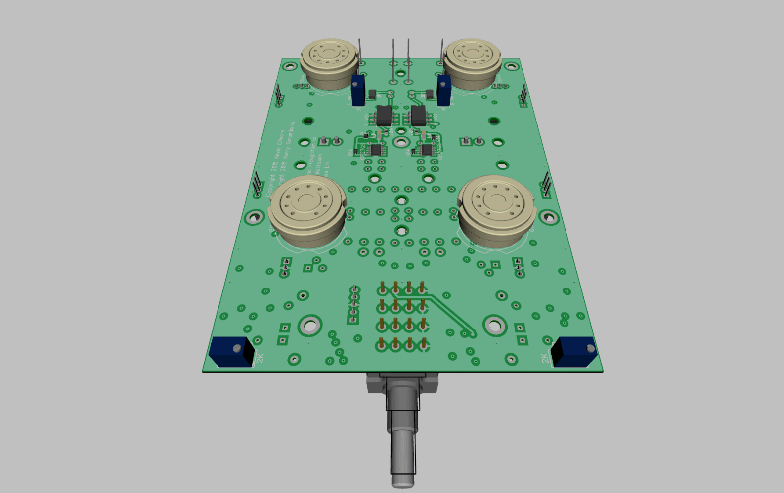
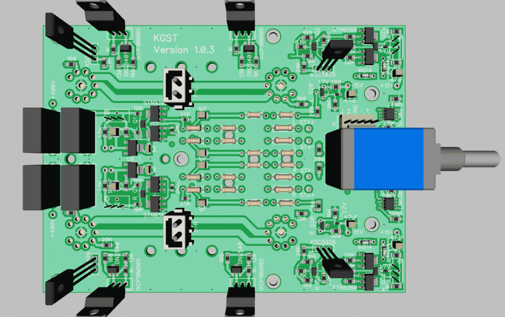
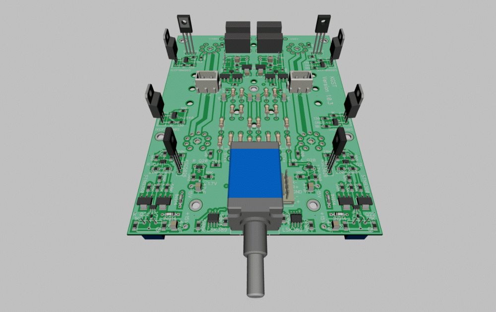
On my first version I did the heater wiring off board. I wanted to get it on the board this time. I used the 4 layers so that there would be a solid ground plane under the heaters and between any signal / voltage traces. I also made sure there was some ground plane on top between the heater and servo which at worst would introduce common mode noise.
-
Nice! This is really interesting. I'm going to have to add it to the list.
-
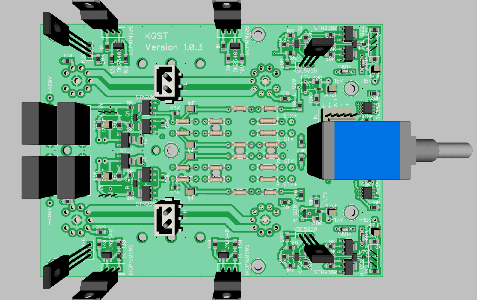
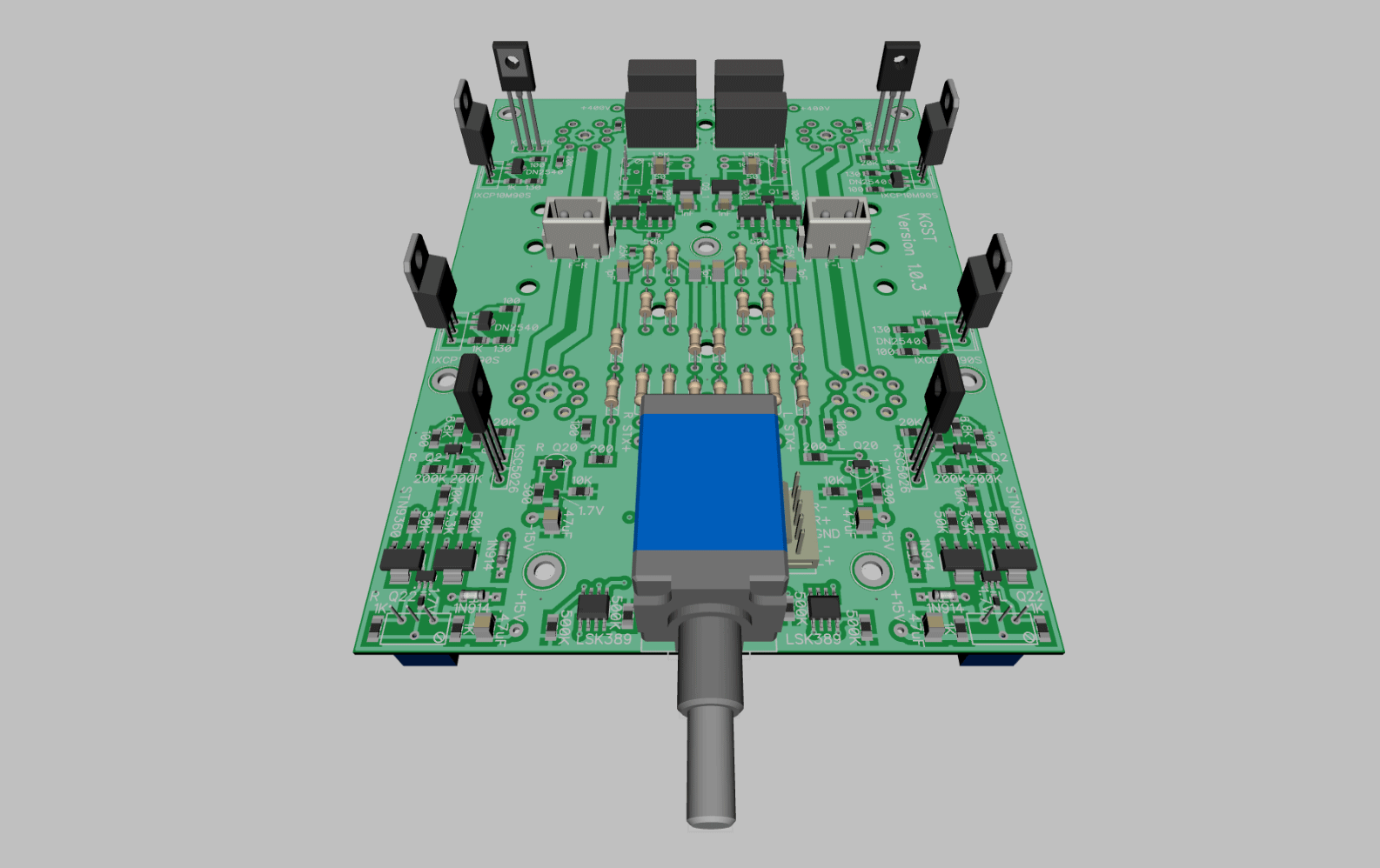
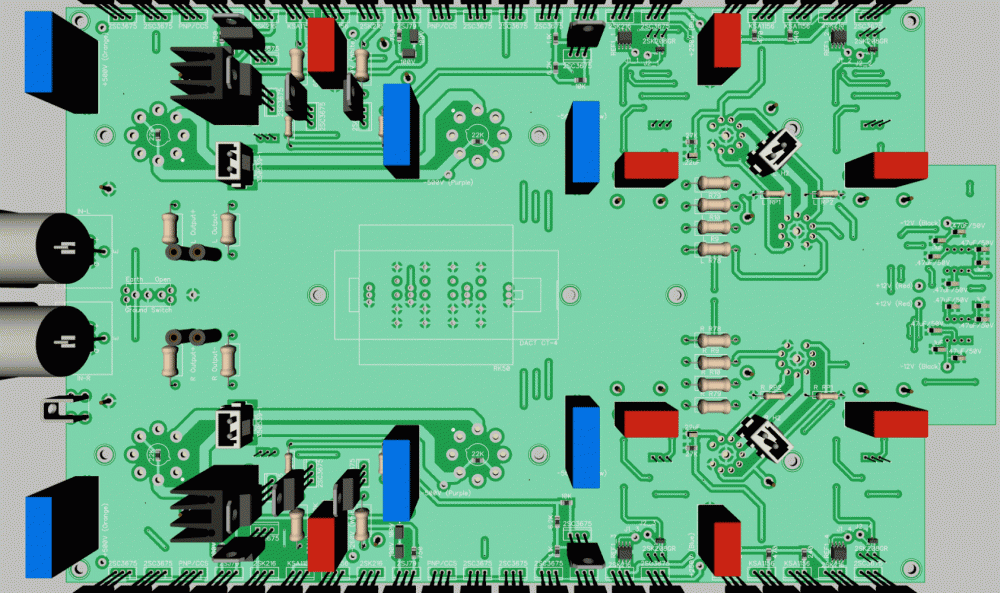
I wanted to redo this as a single 4 layer board. The board is 111mm x 150mm. I'm pretty happy. Should have it back pretty soon and will give it a go. It supports a couple of styles of the servo for the offset so I can play a bit.

-
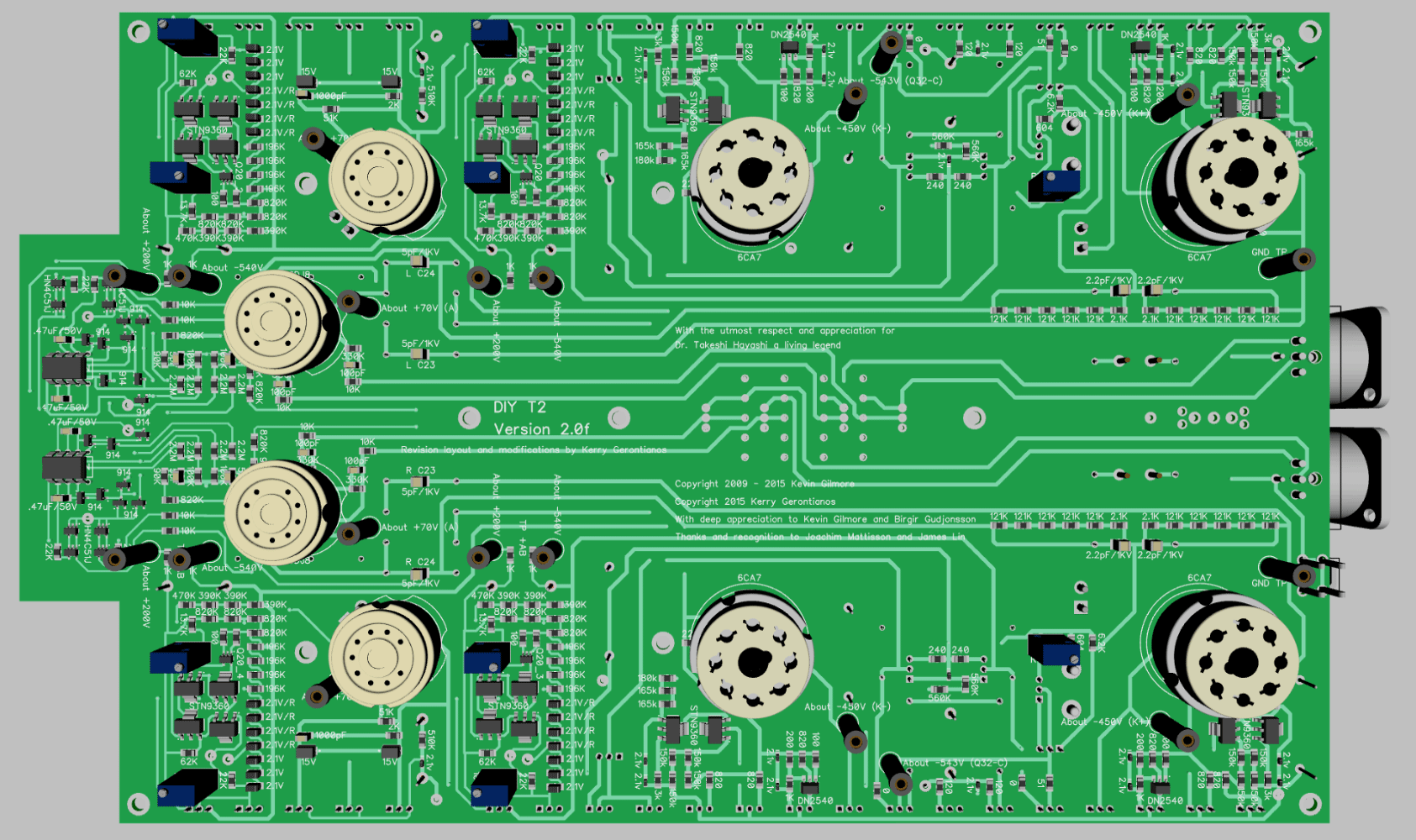
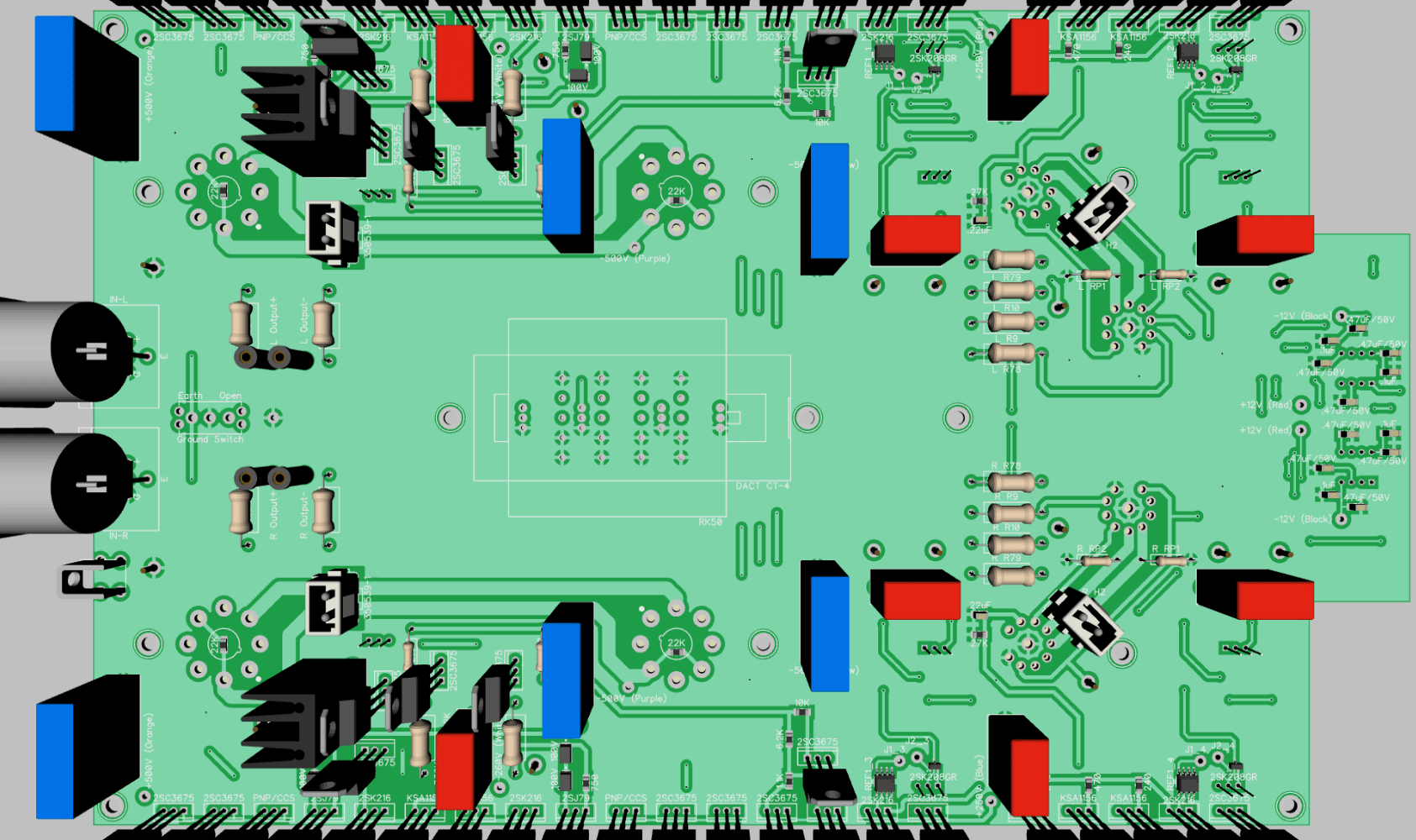
I'm just waiting to get these back. They are my shrunk down boards. The chassis is going to be 12" x 14.3" x 3.3". This will be the same as the power supply. Most everything is SMD now and I'm looking forward to stuffing this in a couple of weeks (I've got all the parts). The boards support two styles of batteries (jfet/LED or LT1021-10). Also they support both the original CSS as well as the 10m90s / DN2540 (thanks to JimL). I have to give props to Kevin and Birgir who did the original layouts. This thing is a beast with over 540 components.

-
-
The noise seemed to be caused by leakage between resistors and possibly to the ground plane, though since I had lifted all resistors (PRP & Xicon) it doesn't seem like it was the ground plane. I agree that the noise was not an issue having to do with external sources. Regarding noise measurements on the PS boards, I'm using custom boards so I don't think my results will carry to the GB boards. Also, unless I screen my room, I would not likely be able to see any differences in performance unless they were fairly large (>10mV).
-
Happy Birthday Tom Enjoy!
-
-
Another site to look at is speedymetals.com, though I don't know if they ship to Australia.
-
I've been following this for a while with great anticipation. Really glad it's out. Congratulations! I've already got the z1 board. I'll probably do one stock y3 and then use some of the components to do something more custom. Thanks for all of your efforts with this.
-
Definitely in on 20 pieces. Could do more if it helps.
-
-
-
Absolutely gorgeous! What treatment did you use on the top copper? I love the piping on the heat sinks
-
Congrats
-
I spent ten years learning the drums. The first eight were about precision the next two were about forgetting about being precise. My last teacher used the word cats in every sentence and always wore dark glasses. kind of like math when they teach you numbers don't exist. It's the next level and so much better.
-
I was just listening to someone play an acoustic guitar on a subway platform in New York. Sound production was spot on and beautiful. I just need to get more of my favorite artists down here.
-
-