All Activity
- Past hour
-

The Knuckledragger 3rd Memorial Slow Forum Post
mikeymad replied to Knuckledragger's topic in Off Topic
-
Okay. Please do report back when you hear from Mouser, then I’ll explain why I think hFE of 341 is more reasonable than 150 for an STN9360.
- Today
-
sorry. P.S. I wrote my conclusion on 9360 in Mouser. I wonder what the answer will be.
-
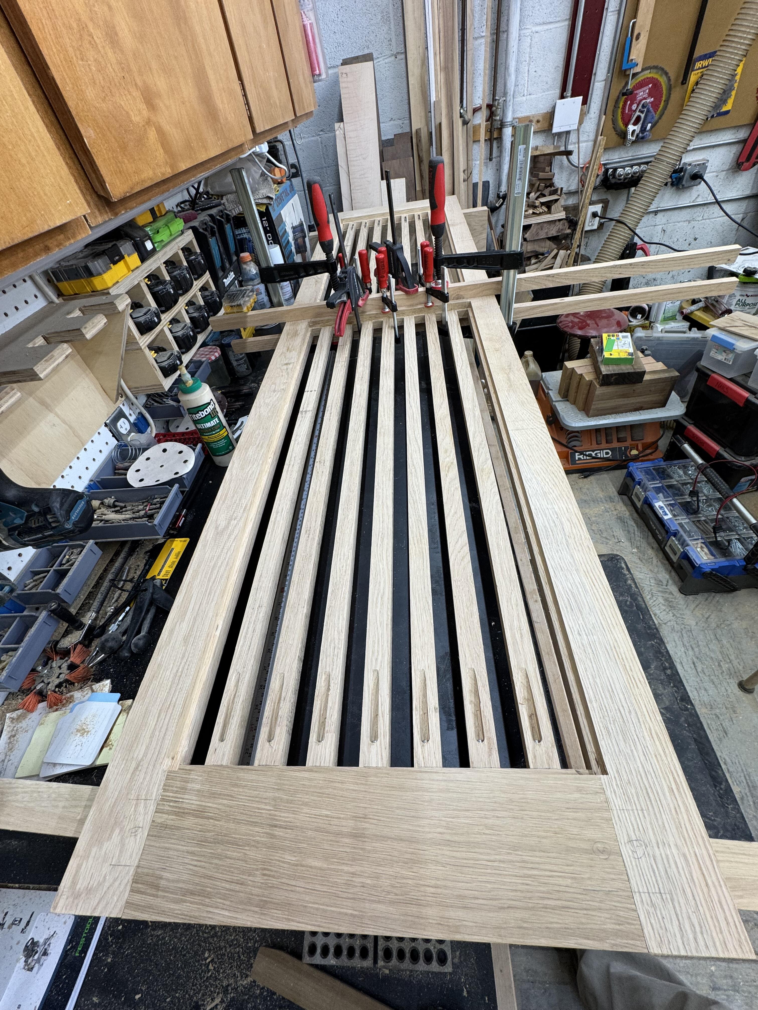
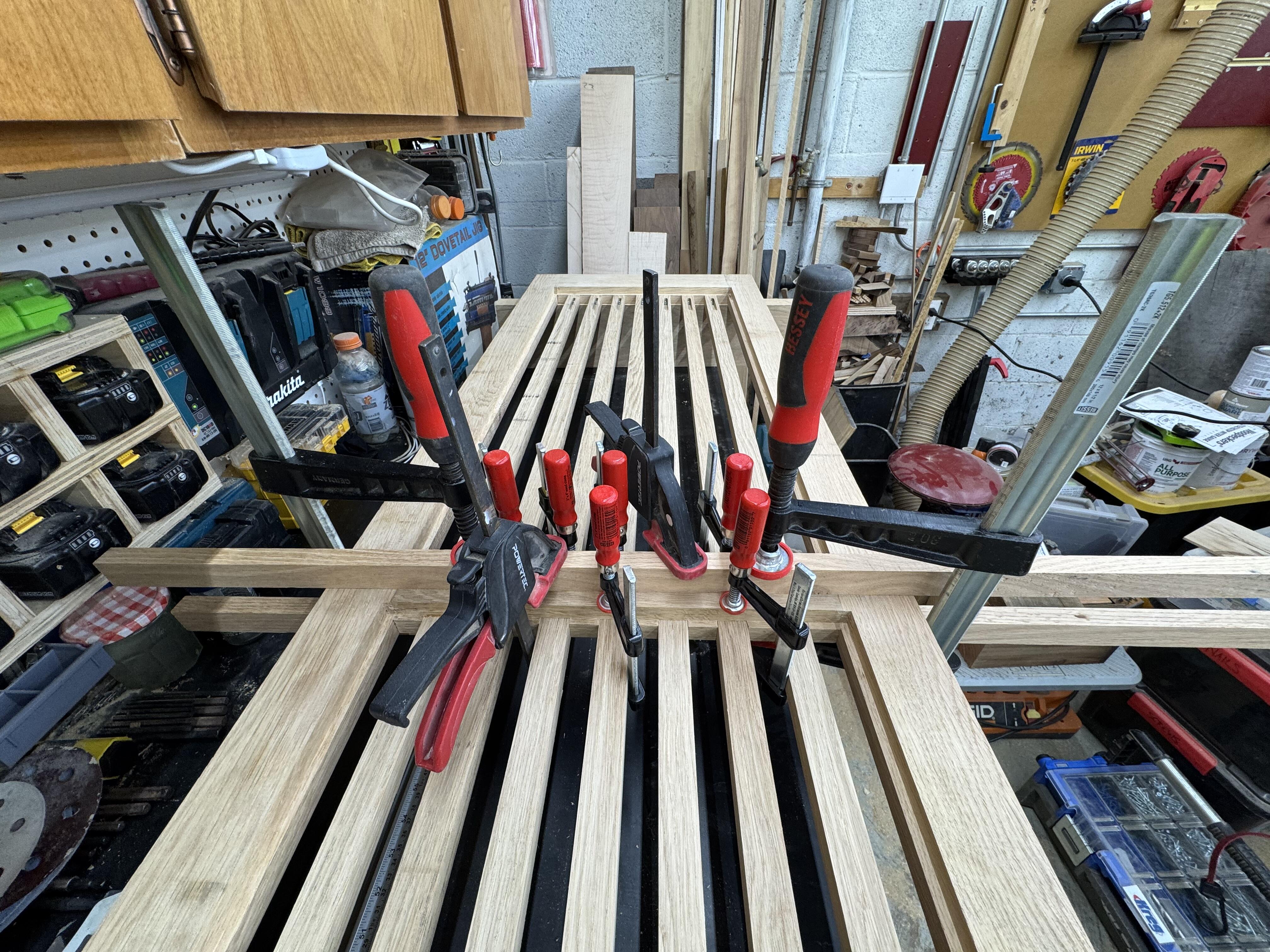
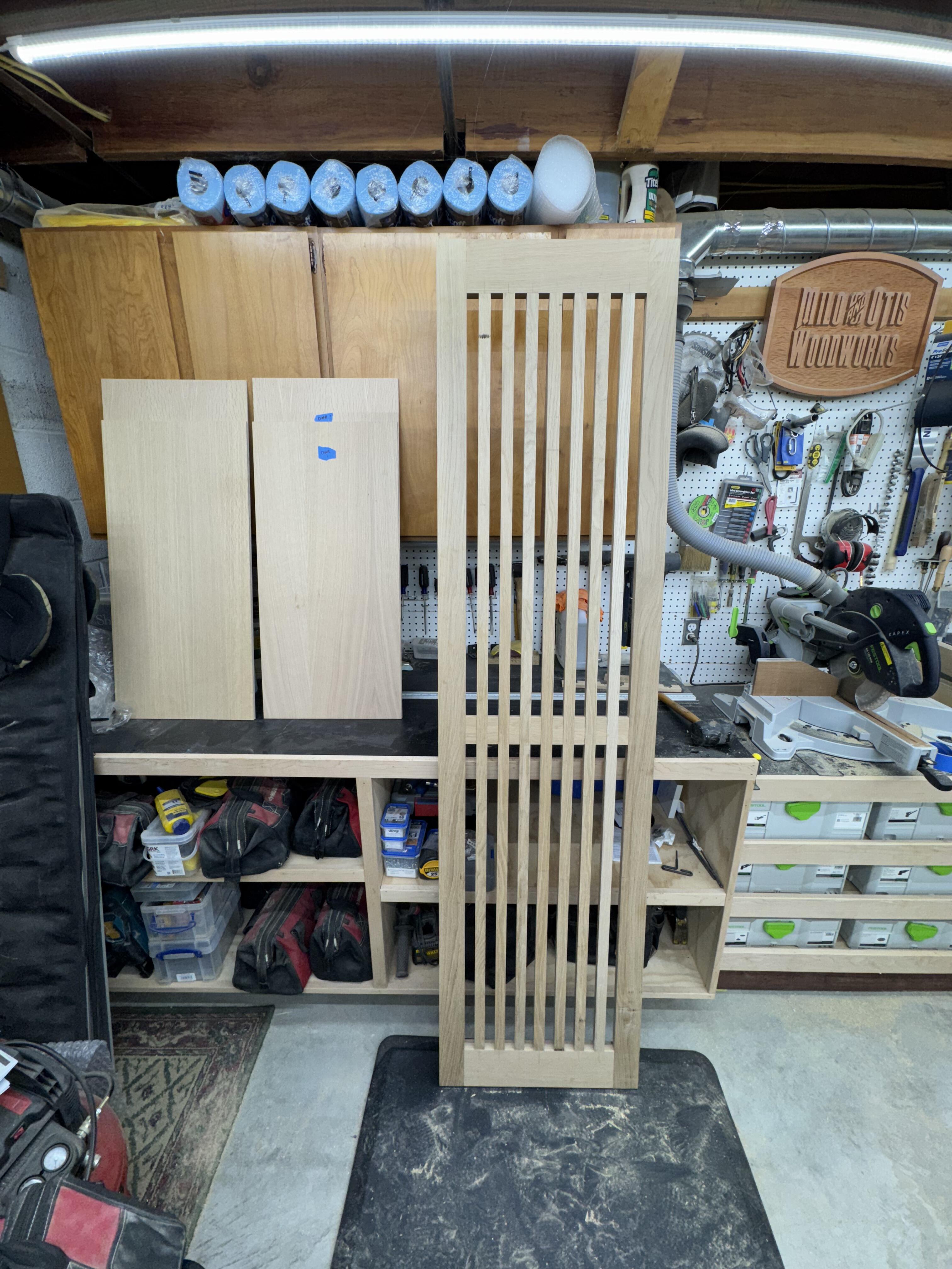
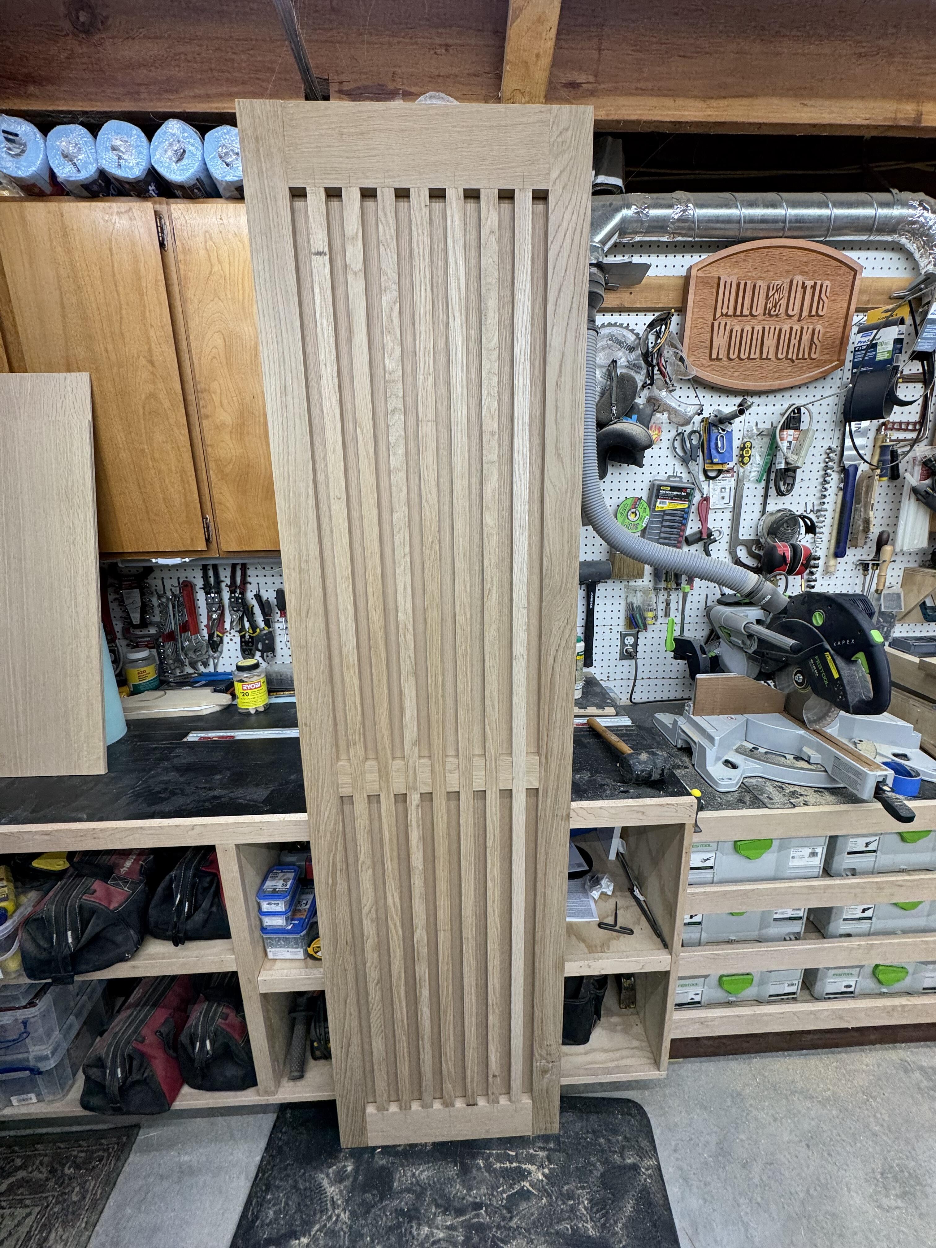
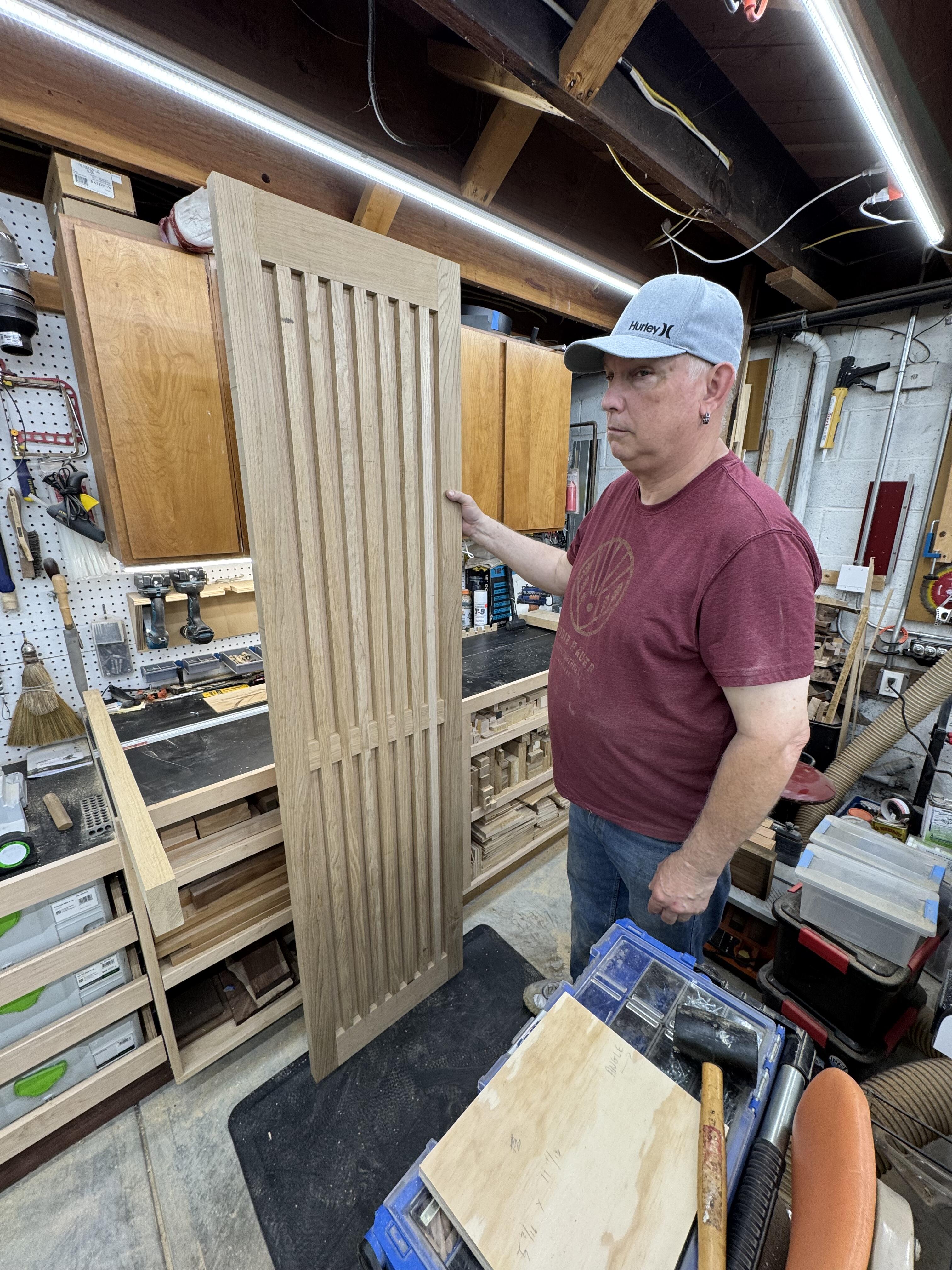
The slatted door style has a lot of intricacies and places for failure. It looks simpler than the actual design. Many dados and places where parts have to fit exactly. But they went together easier than either of us expected. Not an accident, but Al's planning and forthought. Absolutely worth the effort, as they'll be an eye catcher for sure. This has been a rewarding project in several ways. Now that I'm no longer working as a carpenter, it's my much needed release for creativity. And Al and I are really enjoying the woodworking and smashburgers.
-
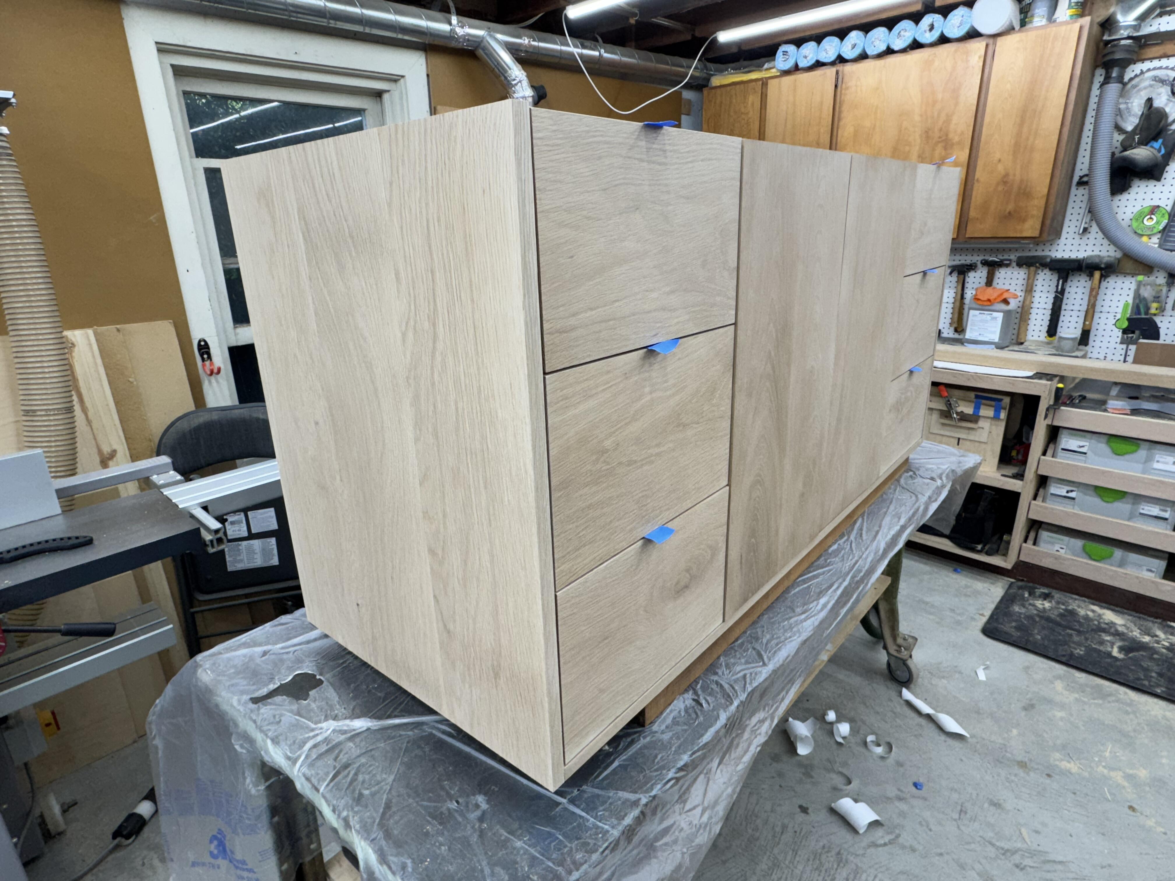
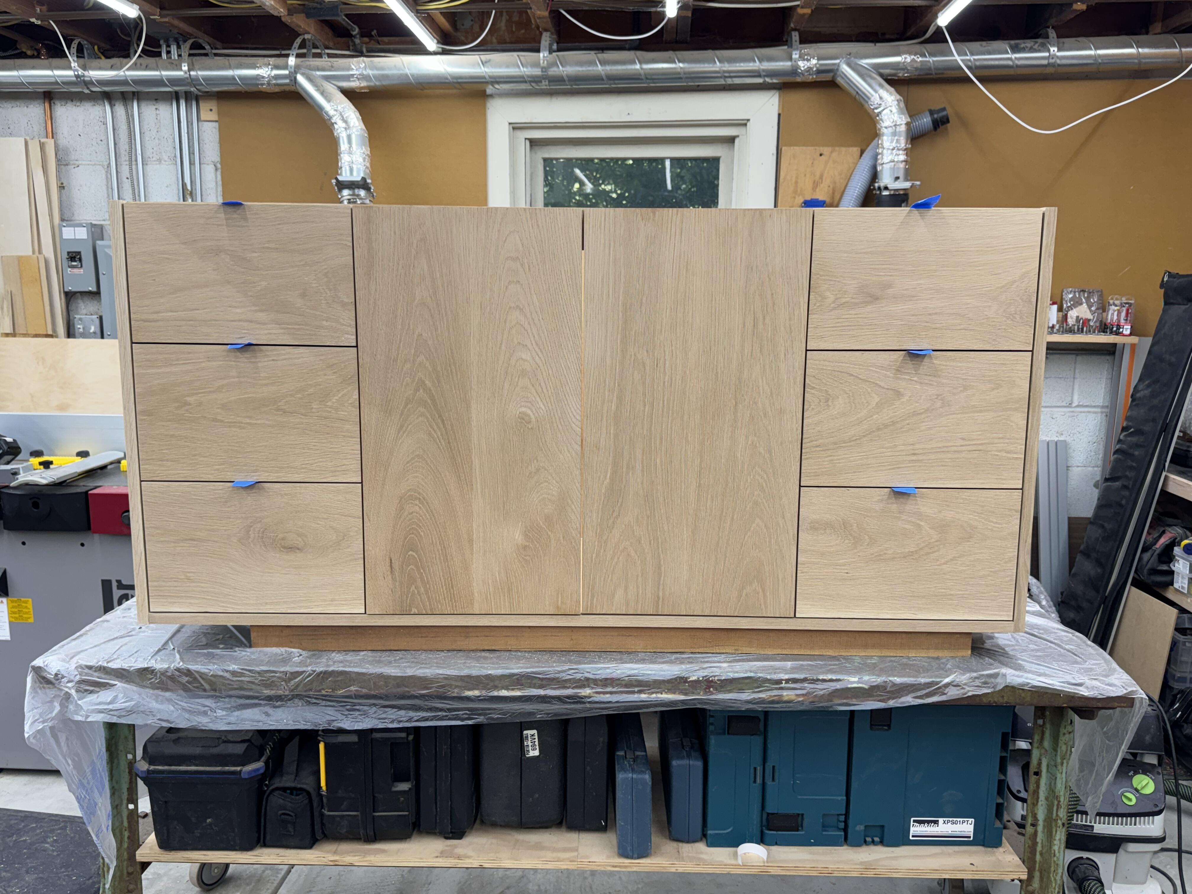
Update on the bathroom vanity cabinet, and some shots of two matching white oak linen closet doors with a slat design. Not fully assembled in these shots but you can get the gist.

-
Are you having a good time, Belvedere? Hip Service were. Serving up a diverse collection of crowd pleasers. Jackson 5, Beyonce, ABBA, Journey. Tight.
-
- Yesterday
-
 Danwen893 joined the community
 -
Your style is not acceptable here
-
You offered your opinion and analysis, I offered mine. Although we disagree, I hope we can respectfully disagree.
-

The Knuckledragger 3rd Memorial Slow Forum Post
blessingx replied to Knuckledragger's topic in Off Topic
Just in case someone can make use of this one way or another. https://www.goodreads.com/book/show/215798863-audiophile
- Last week
-
A quick update on this build. Regarding the low-frequency distortion at high volume that I mentioned earlier, I did some troubleshooting. First, I checked the GRHV output for the +300 V rail. It's extremely stable and consistently holds at 300 V, so it doesn’t seem like any current limiting is kicking in. By chance, I noticed that the D3 LED (next to the 2SA1968 and I'm using STN9360 in this spot) flashes during loud low-frequency passages. That seems to suggest the current mirror may be going into over-saturation. This might be related to the two 150 kΩ resistors labeled R8A101 and R8B101 in the schematic. In the original Megatron, there is actually just a single 150 kΩ pull-down resistor instead of two. That difference might be causing the issue. Also measured the anode voltage of the 12AX7 tied to the current mirror. Under loud, bass-heavy signals, it shows a clear voltage drop from about 355 V down to 345 V momentarily. I’m planning to try shorting one of the 150 kΩ R8 resistors to see if that improves things. Updated: Turns out the current mirror itself was fine. The culprit was actually one of the PSVANE 12AX7 tubes. I suspect there may be a reason these were on sale at TubeDepot. At least the one I got had issues under load. Anyway, swapped it out and the problem is now completely resolved.
-

Megatron Electrostatic Headphone Amplifier
kevin gilmore replied to kevin gilmore's topic in Do It Yourself
probably easier to change the cathode resistors on the current sources. -
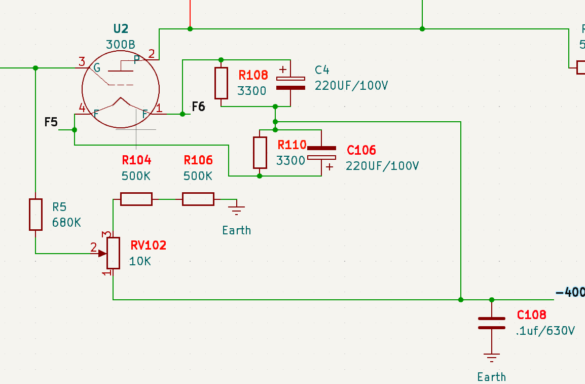
The grid’s pull-up resistor is R5 (680 K), and the pull-down side is two 500 K resistors. The 10 K trimmer (pot) has a very small effect, just about 1–2 V of offset adjustment range. With the current 7500 Ω cathode resistors, Vgk is roughly –76 V. To reach the WE datasheet’s recommended value, the cathode resistance would need to increase further, but that would push the offset even farther out of range. So the grid trimmer really needs to have more authority. The 10 K value is clearly too small here; something like 50 K or even 100 K would likely be a better choice. I’ve noticed that at this: 75 V operating point, there’s slight low-frequency distortion at high volume. I’m not sure if that’s because Vgk is too negative (too “deep”) or not negative enough. Yep, it’s a real hassle. At the very least, having to remove and reinstall the PCB every time is incredibly annoying.
-
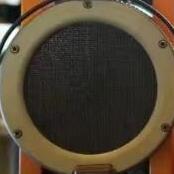
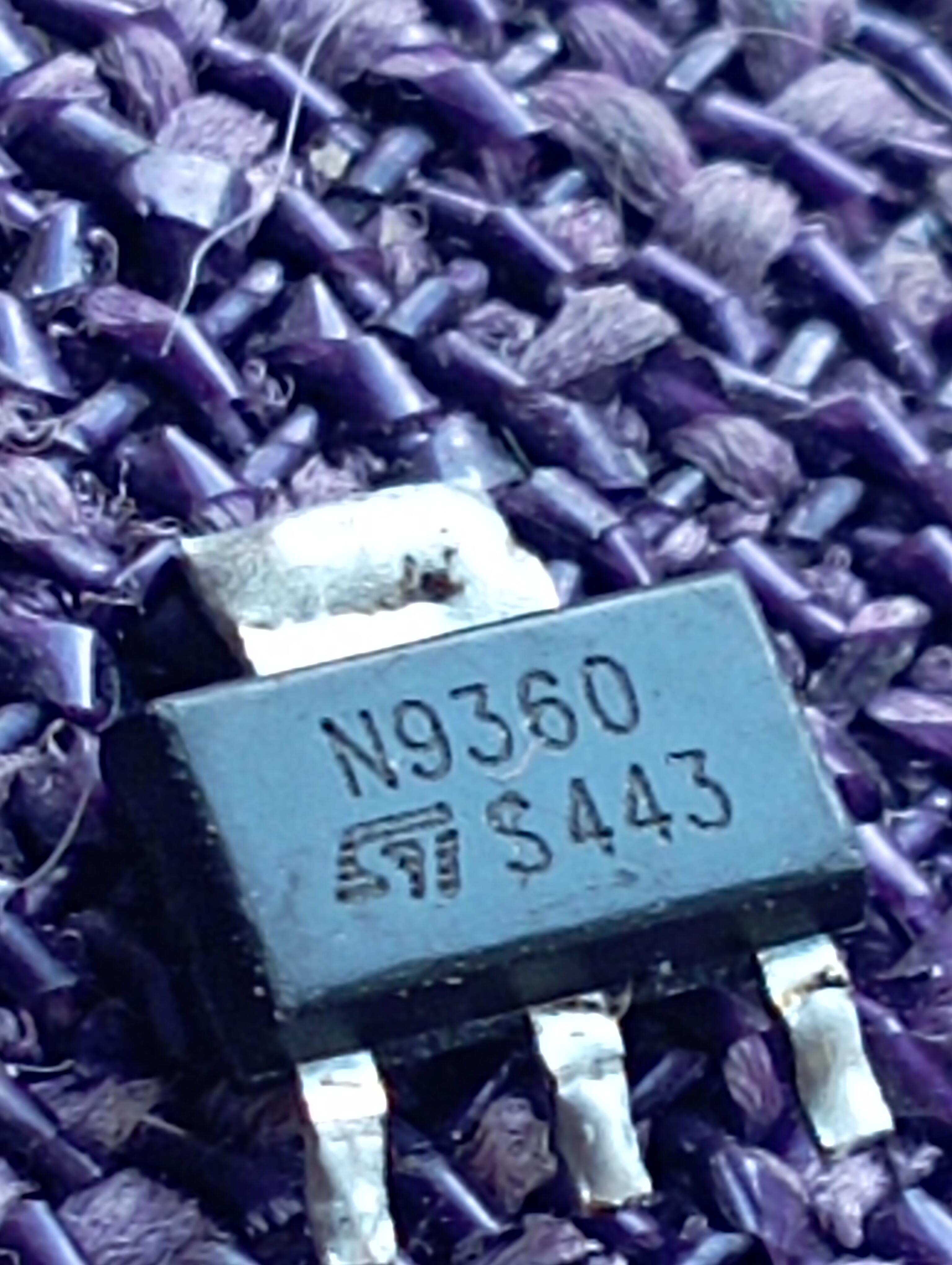
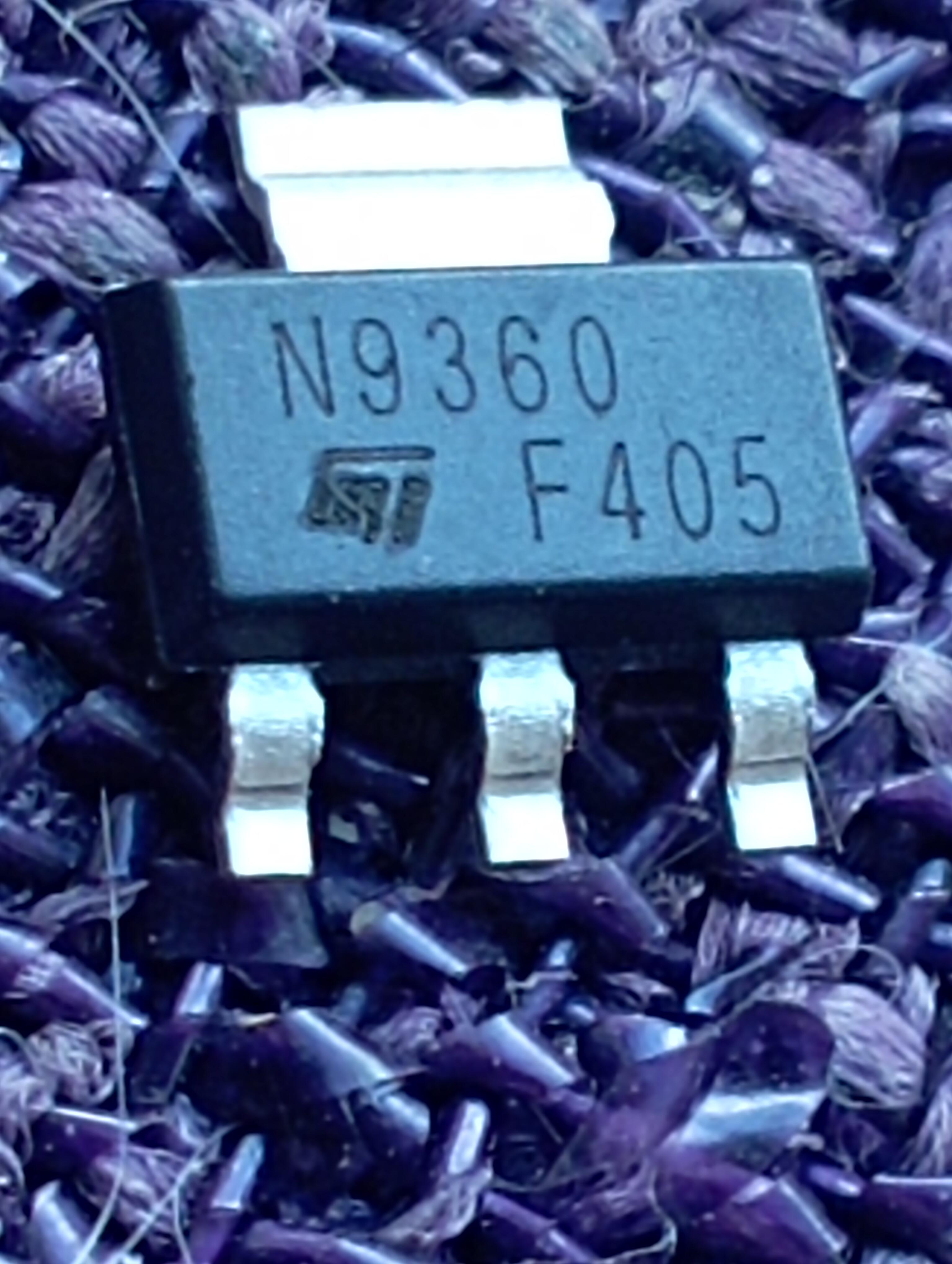
I show photo 1, where I demonstrate a tested sample, with a cool brand engraving. According to the measurements, hFE is much closer to the datasheet - hFE150. In photo 2, an awkward logo. hFE - as much as 341
-
mauser was legit. went bankrupt more than 10 years ago. they produced firearms. german manufacturer. mouser is definitely legit. never got a fake part from them yet.
-
One of our neighbors has a Columbian wife, and has started a coffee company using her family's farm. https://www.orchideacoffee.com/ So we said put us down for a bag when you get started. This week one was hand delivered to our door. Joanne said we should reserve it as a weekend treat. Not too shabby.
-
 Tafin9 joined the community
 -
Ran Blake - Grey December (Live in Rome) Ex.
-
Megatron Electrostatic Headphone Amplifier
kevin gilmore replied to kevin gilmore's topic in Do It Yourself
so more than a few people are getting clobbered with 300b that don't even come close to the original published western electric document. of the 7 different varieties i have, only the original 1960's manufactured western electric comes even close to the spec. and the new western electric tubes come in low vgk and high vgk versions. (The B series tubes) just means you have to mess with the resistors. and yep its a major pain in the ass. the el34 original version pretty much worked +/- a few volts no matter what tube you stuffed in there as long as they all from the same manufacturer. or build a megatronxxl now known as optimus-prime. more money, but less of a balance problem. -
Mouser is legit, ‘Mauser’ is probably not. The one in the first picture is more likely a fake. Even without a known genuine sample for comparison, you can tell by at least two factors: The four top corners of the plastic molding are rounded and inconsistent, suggesting that the package may have been sanded. The ST logo is a raster image composed of parallel horizontal lines, suggesting that it is a scanned reproduction. A genuine product would have a vector artwork since it is the manufacturer’s original design. Other factors such as the laser marking font or etching depth can vary from manufacturer from manufacturer and even from factory to factory. You would need a known genuine sample for comparison. A low cost transistor tester such as DY294 can test breakdown voltages up to 1kV and measure hFE at different collector current settings. You can choose one that’s close to the transistors’ actual operating point. DY294 Digital Transistor DC Parameter Tester Field Effect Tube Tester Multifunction Semiconductor Tester https://a.aliexpress.com/_mqGVojt
-
get yourself a high voltage transistor tester and make an adapter board or solder wires to test subject. in this case it absolutely has to have a breakdown voltage of about 640. but in any case >600 the second part is likely genuine. no one is going to pirate a $1 part. the big hfe change i am beginning to see more and more of.
-
Chris Rea - The Road to Hell
-
 Petr Obst joined the community
 -
I have a question for those who bought 9360 from Mouser. Is Mouser 100% trustworthy? I bought STN9360, I see big difference between two other units I bought some time ago. 1 photo/ in the first photo with hFE -150 in photo 2, what mouser sent. here brand badge as a fake. hFE -341, and there are 15 of them.
-

Megatron Electrostatic Headphone Amplifier
JoaMat replied to kevin gilmore's topic in Do It Yourself
How much offset can you trim away with the trimmers? I guess one need about 15K to get rid of +10V offset (with 2 x 500K resistors in the voltage divider). -
Today the 7.5 kΩ resistors I ordered arrived. To swap all eight cathode resistors I pretty much had to remove every screw on the chassis. Long story short, the offset is much improved, going from –100 V to about +10 V. Big thanks to @JoaMat for the help! For me, this voltage is acceptable, but if someone wants to get even closer to 0 V offset, I think 7.0 kΩ might be the sweet spot. Also worth mentioning: the G-grid adjustable pot on the board offers around 2–4 V of Vgk trimming range. My 300Bs are running at ±400 V, since I feel 450 V is pushing things a bit too much. I think the main reason(Correct me if I'm wrong) for the original –100 V offset was that the cathode resistance was too low, allowing too much current. This made the anode current too high, and because the EL34 CCS isn’t perfect, it compensates by lowering its voltage output. With the original 3300 Ω resistors, I saw the B+ drop from 400 V to 370 V under load. One more note: after increasing the cathode resistor, Vgk sits around –80 V. For safety, I’d recommend replacing the original 220 uF/100V cathode bypass caps with 160V rated ones. More pictures will be posted later.