

Leaderboard
-
Hopstretch
High Rollers9Points16780Posts -
Voltron
High Rollers6Points34514Posts -
acidbasement
High Rollers6Points2987Posts -
mikeymad
High Rollers6Points13710Posts


Popular Content
Showing content with the highest reputation on 10/25/18 in Posts
-
3 points
-
3 points
-
2 points
-
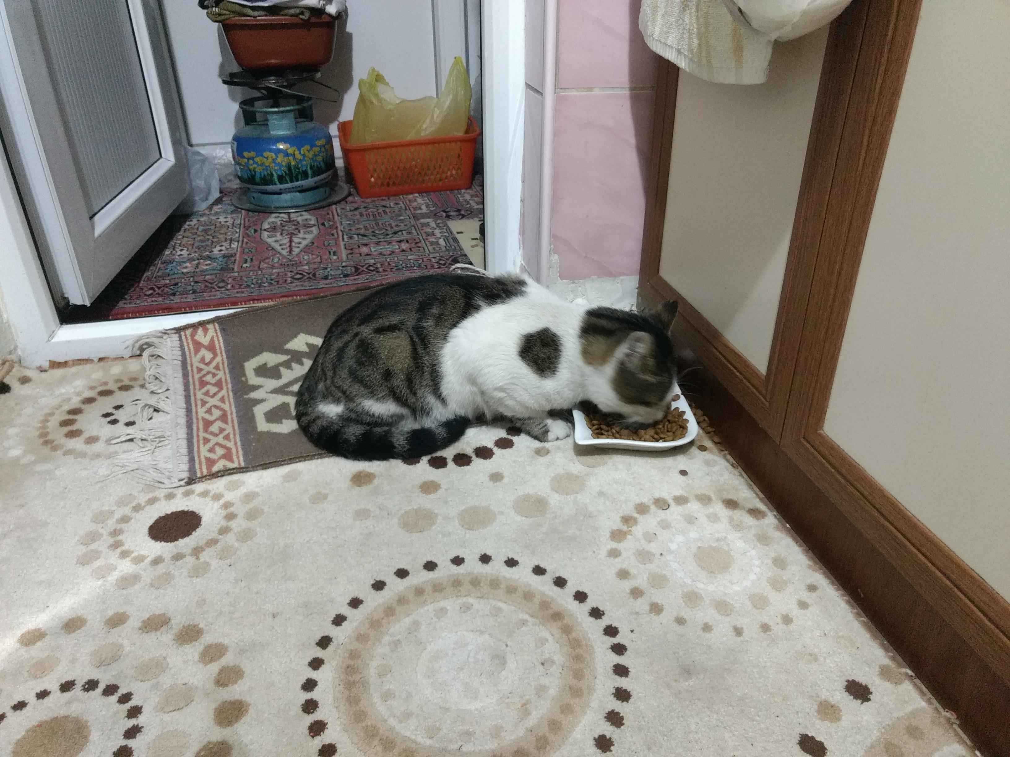
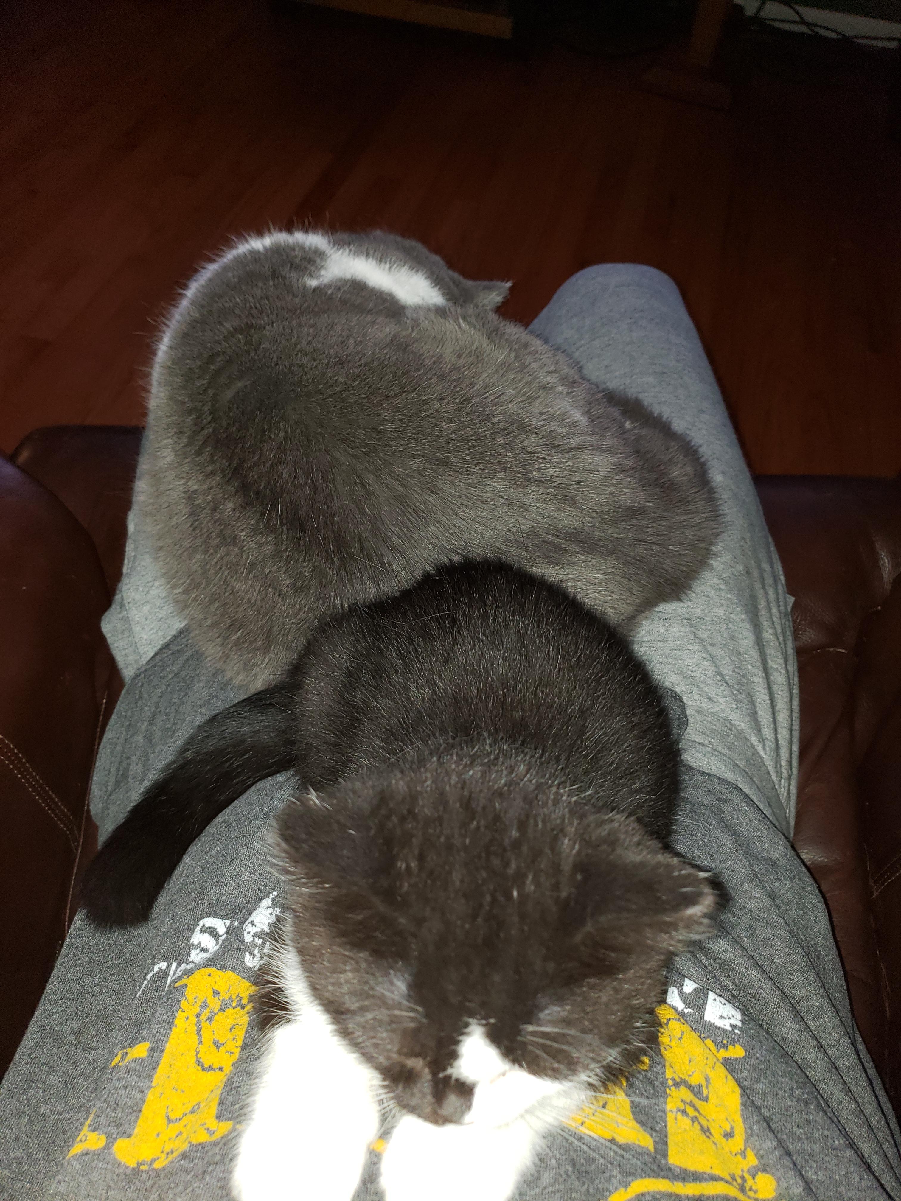
2 pointsI took the cat to the vet to check for a chip. He was an escapee, apparently. I guess I did my good deed for the day, but I’ll miss him.2 points
-
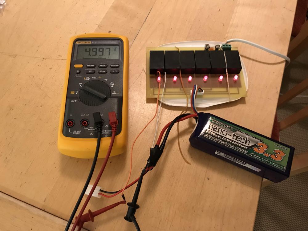
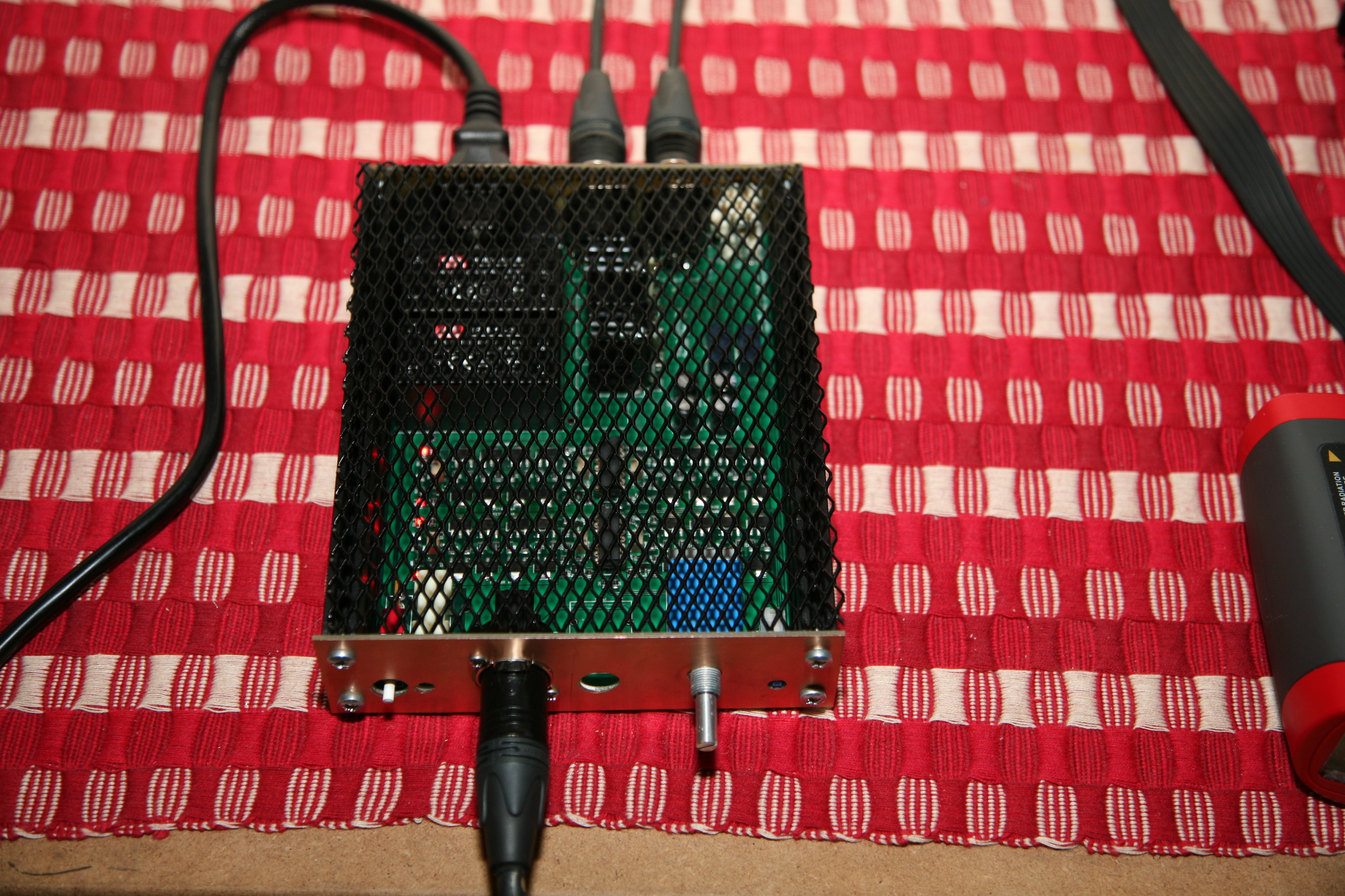
1 pointFound this in closet. I guess it’s some kind of charger I built a couple of years ago. Six Mean Wells and charger regulators and each cell has his own charger. Red light will probably turn green when fully charged. I don't remember but I will see in a couple of hours.
 1 point
 -
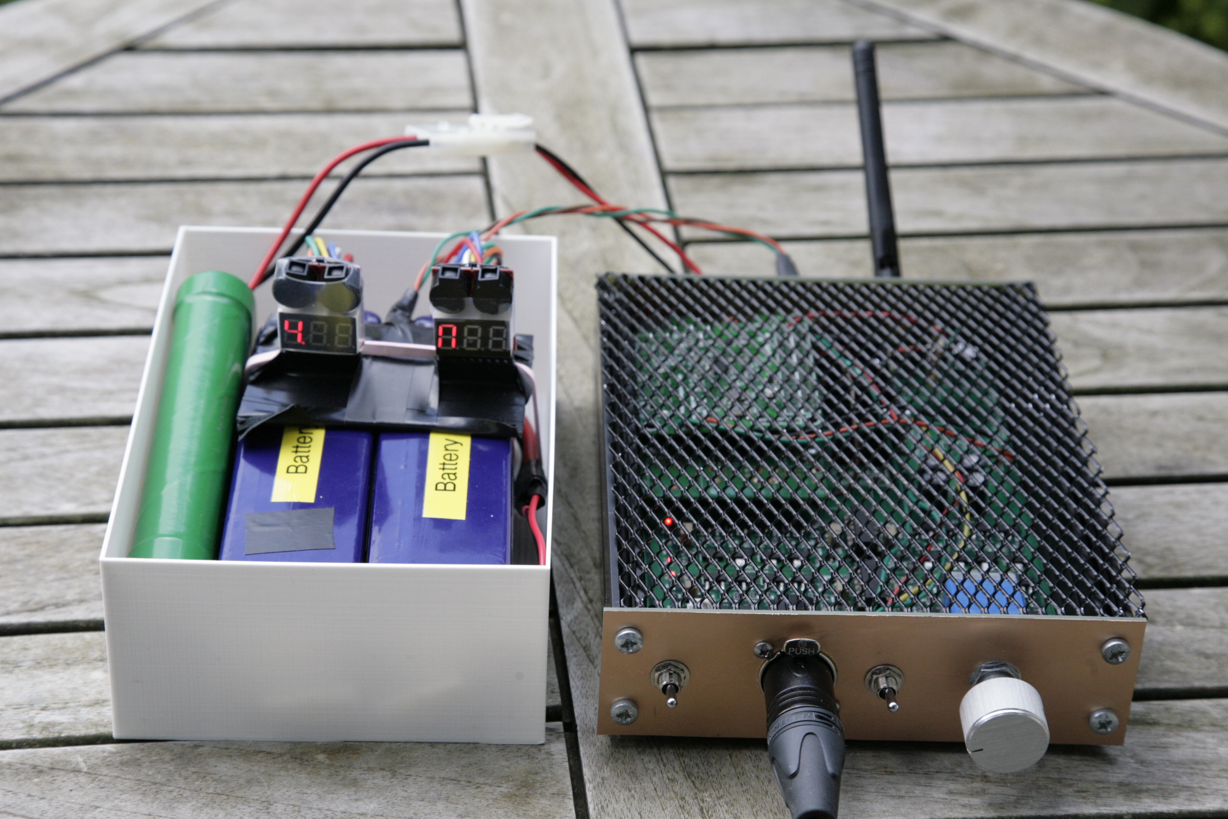
1 pointI used the battery pack summer 2016. LiPo 6 cells, one pack each rail, give you some 22 volts reduced by the regulator. Those LiPo packs are used by RC people. I bought from hobbyking.com.1 point
-
1 point
-
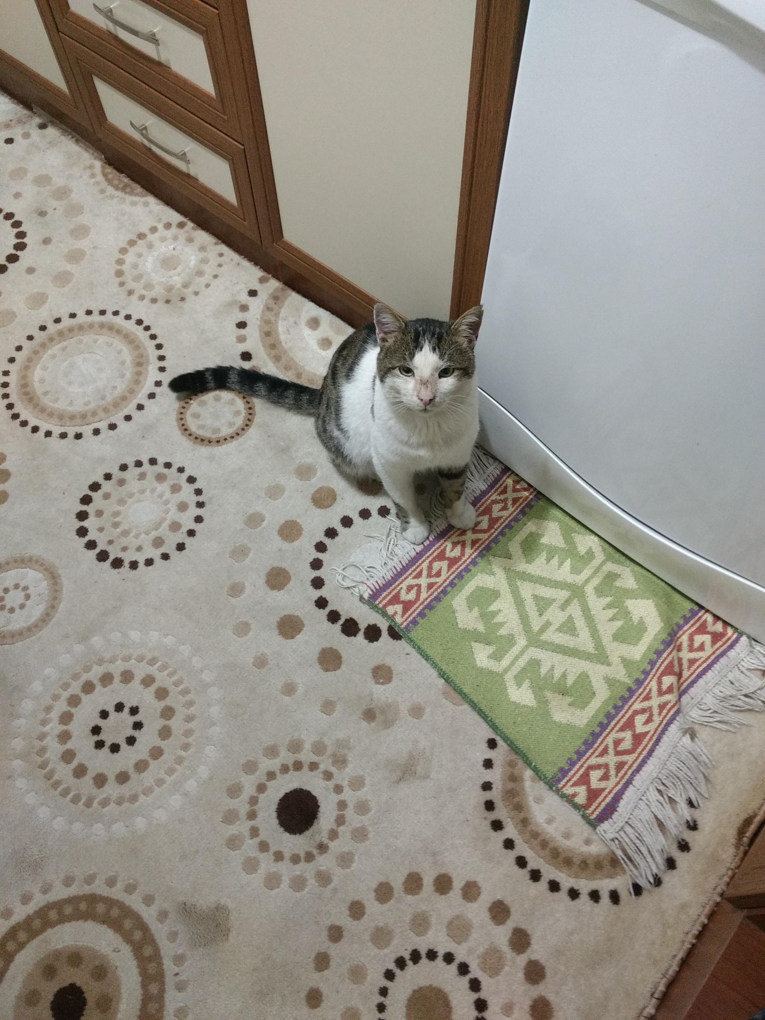
1 point1 point1 point1 pointAnyways, here's my 2 eurocents. It's really all about the features and wether you care to benefit from them. It comes with a 100 page manual and it's worth to actually go through it. Almost every aspect of it makes the purist stuff from most audiophile mfg's look stone age. You get one of the best digital volume controls out there, 5 band stereo PEQ, unique loudness compensation, dicking around with DAC filters, all kinds of X-feed and much more. It measures impeccably. I'm half sure that my Pro can give lab grade measurement stuff from AP a run for their money. As for the sound, I enjoy it. If you're used to THD, then it might feel too naked. I've heard people say that. Simple music like strings with solo vocals can sound richer on dirtier sources, the problem is that this richness gets in way of spectrally busier records like metal and such. And I personally like to feel that what I'm hearing is the truth, even if there's no direct way to know that.1 point1 point1 pointMy cancer kitten was thrown away, apparently, but I adopted a three legged buddy off the street, today.
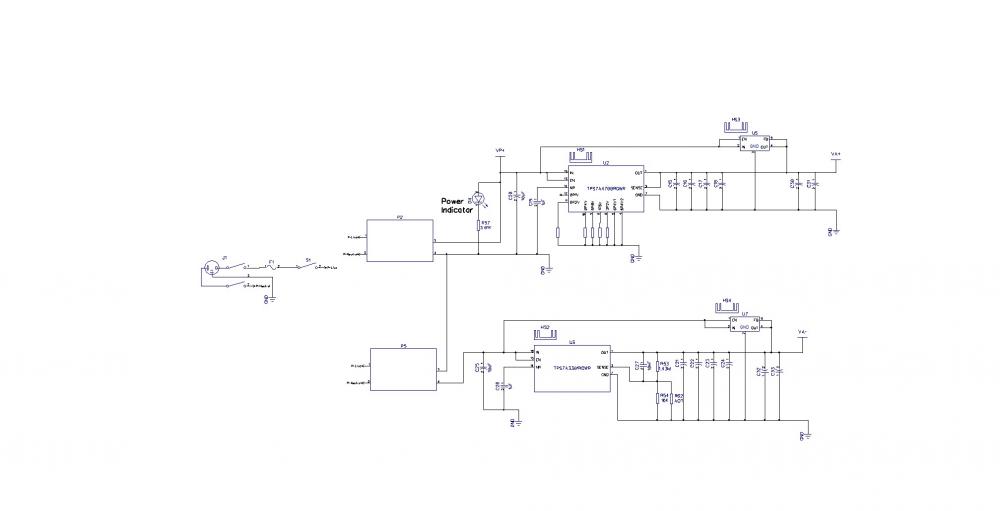
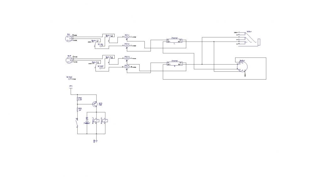
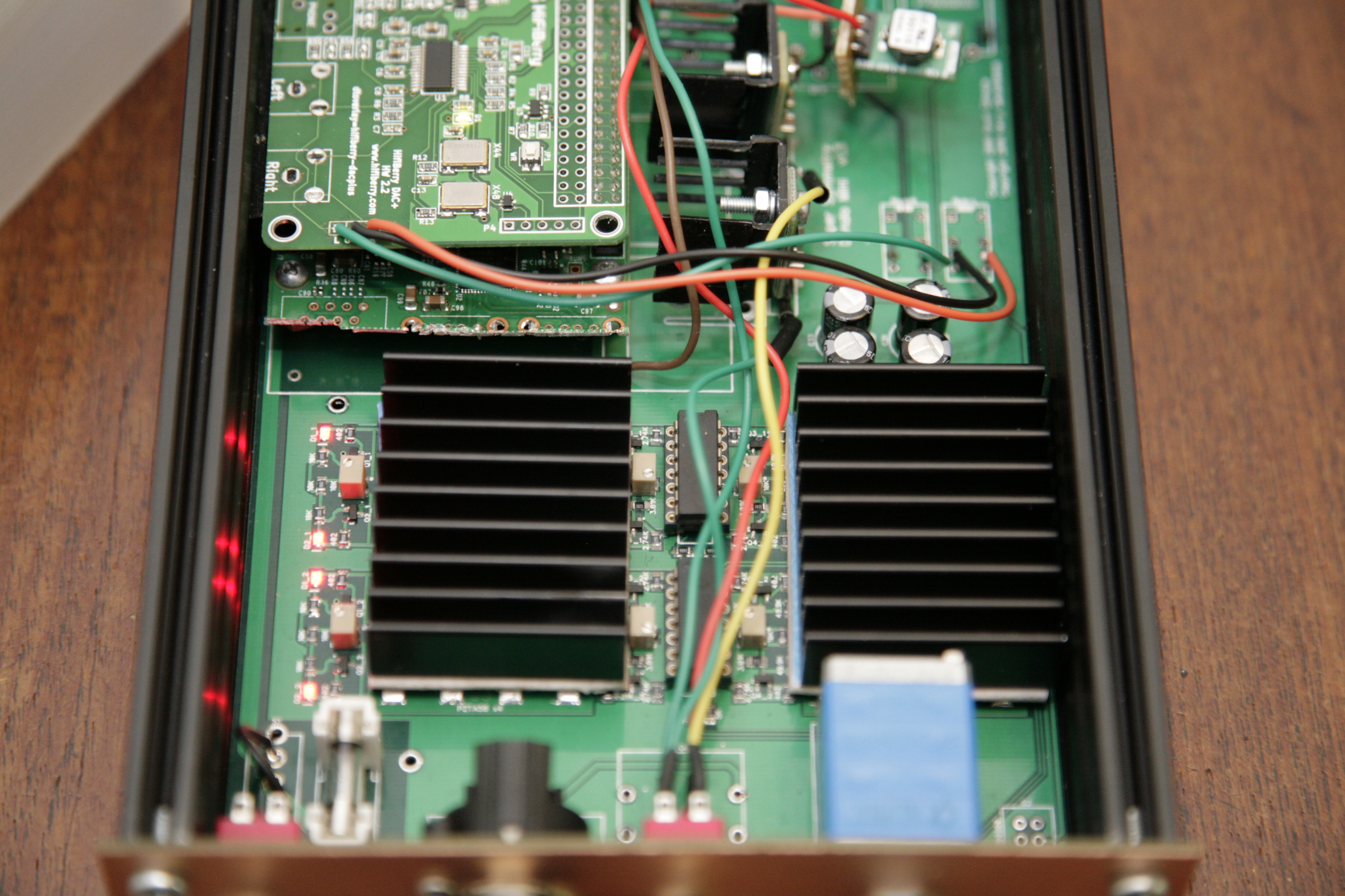
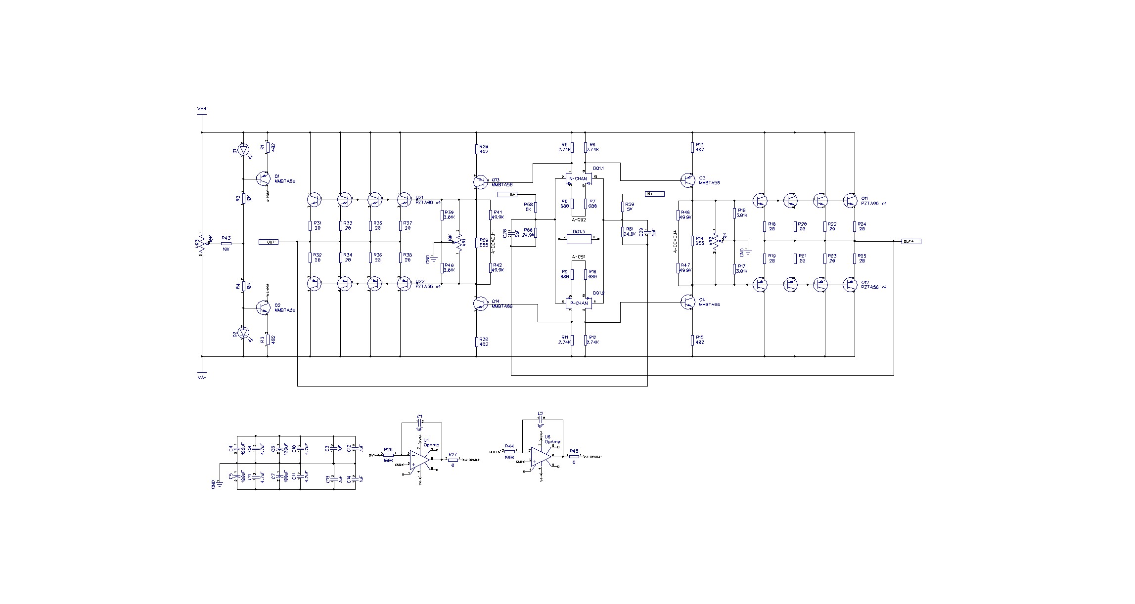
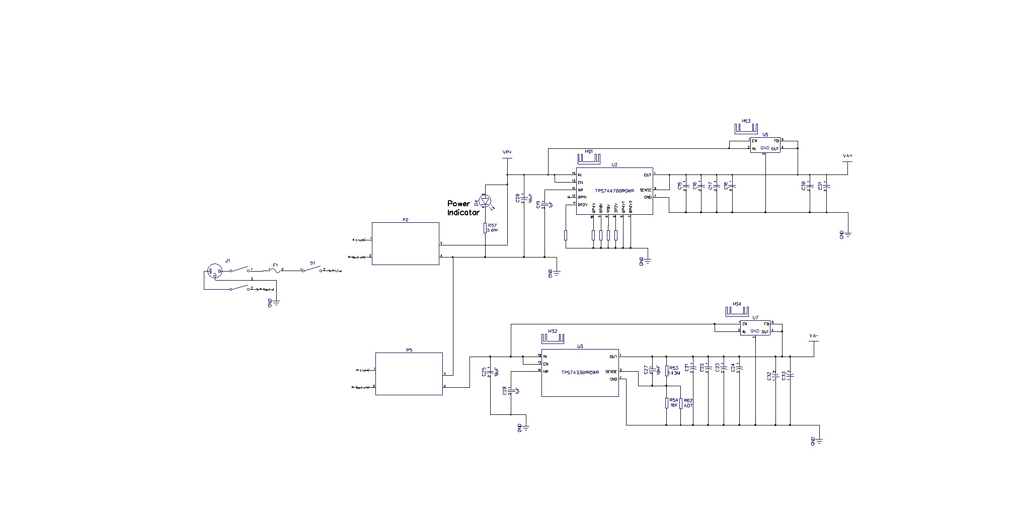
 1 point1 point1 point1 pointYes. Run a bead of silicone caulk around the ear pads and seal it to your head.1 point1 pointInteresting problem, at least to me, and might help someone in the future with these. Fired up the 3rd board yesterday, and all looked well (LEDs, etc.). However, there were problems: Problem 1: Went to check DC offset, and the R channel (both +/-) was showing 4V offset. Not good. After looking the board over, I suspected one of the small transistors (MMBTA06/56), as there were a couple that were a bit crooked and I couldn't tell if all pins were soldered or not. Q3_2 looked suspect, so removed with hot air, which also took the 3.01K resistor right by it. Cleaned and fluxed the pads and got it put back together. I also touched up the solder connections on the others on both channels in this section of the board. Fired it back up, same problem. I then looked at Q1_2 and Q2_2. Straightened these and touched up the solder joints. Success! But I wasn't quite done... Problem 2: Adjusted DC offset (no pot in yet, so will recheck once that is in). I then started going down the 20ohm resistors checking the biasing. All looked good until I got to the L+ channel. These alternated from 290/220mV (they should be balanced between the NPN and PNP sides). The 20 ohm for the closest to the center NPN showed no drop across it. I retouched the solder joints for this transistor, but same problem. Removed and replaced the transistor. Success. Now bias was the same as the other channels and consistent across all resistors. Ohming that transistor out, it appears to be good. I couldn't see any evidence of solder on the bottom of the tab (collector). I know when I checked voltage on it, it showed V+, but I was probably pushing it down with the probe. The collectors aren't connected on the middle small pin on these from what I can tell in the gerbers. I had used hot air to install these originally, but had hit the tabs with an iron with a wider chisel tip. These are considerably more difficult to troubleshoot/rework than the full size dynalos are, so it pays to take your time building them. Before I checked the end transistors in #1, I wasn't relishing having to do more extensive troubleshooting/rework on this. The other two boards came right up with no problems. And I'm still not fond of SMT pots Also, since I don't think this is documented anywhere, with the board facing you (pot, outputs, etc.), looking at the channels as quadrants, they are laid out as follows: L- L+ R- R+1 point1 pointHere are the schematics: I've got to look up the settings again for the positive rail. I'm running out in a bit so may need to do it later. EDIT: Ok so the silk screen should read 14.2V before you start bridging the jumpers. You should bridge 3P2V, 1P6V, 0P8V, 0P2V for a 20V output. Also, updated schematics to make them higher resolution.
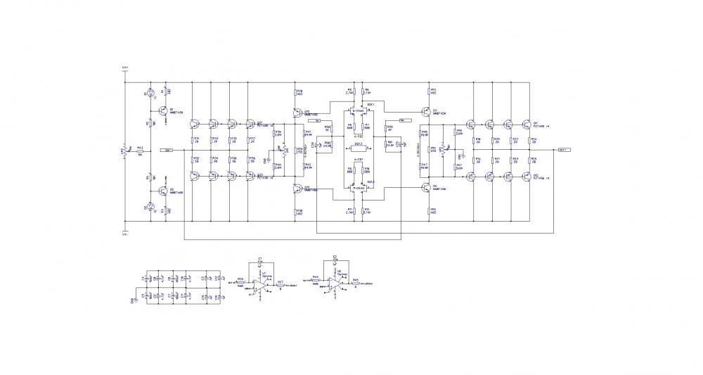
 1 point


Important Information
By using this site, you agree to our Terms of Use.