

Leaderboard
-
Voltron
High Rollers6Points34512Posts -
morphsci
High Rollers5Points13301Posts -
Augsburger
High Rollers5Points13165Posts -
Hopstretch
High Rollers3Points16779Posts


Popular Content
Showing content with the highest reputation on 11/07/23 in all areas
-
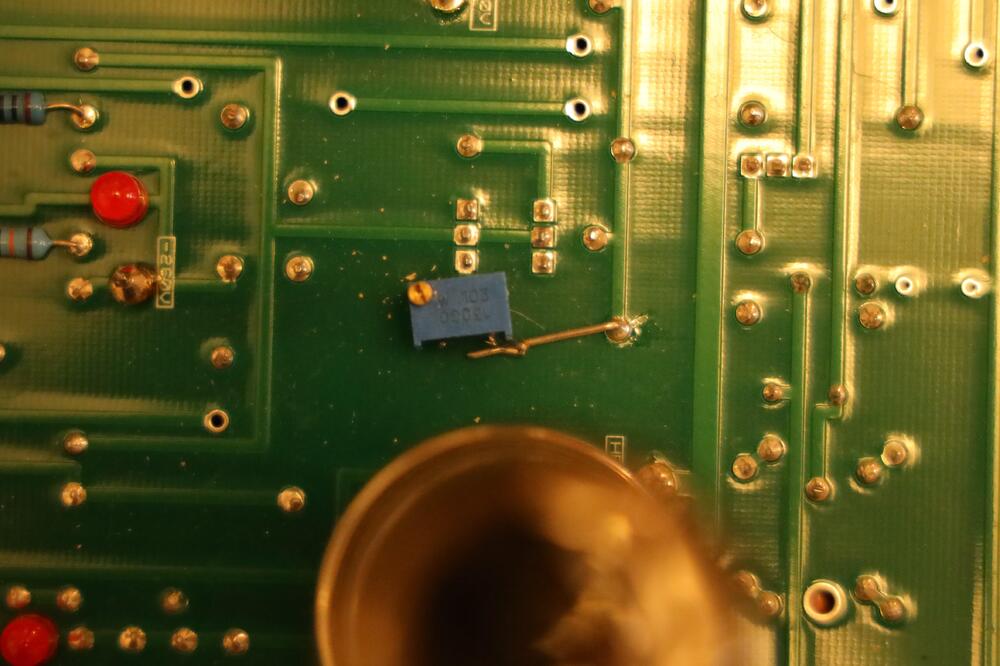
2 points2 points2 points1 point1 pointNew toys by Sony. Kind of impressive that global shutter thing.1 point1 pointA simple way to adjust offset is to replace R73 with a 10K trimmer. Looks like this on my amplifier. Works like a charm.
 1 point1 pointSeems your balance servos are working since C and D have same readings. As for right channel where you have unbalance – investigate the R88 – R91, C8 and C9.1 point1 point@jokerman777 I'm not sure what problem you have with the battery now, especially with the working channel. Can you still reproduce the problem in your post? It's normal to see both top and bottom voltage changes as your battery voltage 'contracts' or 'relaxes', since multiple feedback loops are in action trying to compensate the changes. I'm not too worried about Hfe of Q23. You probably already did the math. At 740V battery voltage, the current through Q23 is about 3.23mA. Since R39 passes about 0.1mA, Hfe of Q23 should be at least ~33 in order not to starve the Q16/19/20 branch even in the extreme situation. The original design seems so marginal, since the 2SC3675 is spec'd for Hfe>30. The good thing is that in reality, the C3675 has a quite slanted output curves unlike the datasheet suggests. Its effective DC gain increases as Vce increases. One of my samples measured at Hfe=38 with Ib=10uA at low voltage on a tester only needs about Ib=40uA to get Ic=3.2mA at Vce=740V. Essentially you get doubled Hfe in the real circuit compared to on a transistor tester. Sorry my CRT curve tracer has a broken flood gun so I can't show you the complete picture. Ib=40uA is still a large chunk of the 100uA from R39, which seems to be different from one would think, that the load current is usually a small fraction of the DC operating current of either arm in a diff amp. I think your way of reducing R39 is in a right direction. If I were to take a wild guess, the R39 could have been 6.2k (Blue-Red-black-Brown) instead of 62k (Blue-Red-black-Red) in the original T2 design. You see that besides the tiny decimal point, the color coding is also very close to each other. It's not uncommon that such mix-up could happen in any stage of manufacturing, and copying. With R39=6.2k it'll make the A1486s operate at a comfortable 500uA each and still within 200mW which is okay without a heat sink. I would expect the adjustment to be less finicky now that the main amp has a lot more juice and the output device has 30% less load. More importantly, some of my genuine C3675 show onset of breakdown at Ic=3.2mA, Vce=740V. Getting the current down would also help on that. By the way the A1486s has excellent low current linearity that's probably why the battery had worked at all under such a low current. Regarding the battery current, the R62/63/74 also drain some current so it needs to be added to what you measured on R58/59. Let's get your math straightened out. From -561V to -541V it is going UP and not down, this is important especially when most of the circuit is referenced to B- (-560V). For the Q32 and Q33 in the channel with large offset, have you measured their Vbe separately, and compare with the good channel? I hate to repeat myself, but you've got to measure all nodes. When something isn't working, every component and every connection is a suspect until proven otherwise.1 pointBeen picking up more photo books, but the one I was most excited about this last month was the title I thought best captured those early pandemic days. Maybe a bit on the nose, but how do you show the lonely alienness of those first 6-9 months? Anyway, Andrew Rovenko's The Rocketgirl Chronicles (Backyard Space Travel)
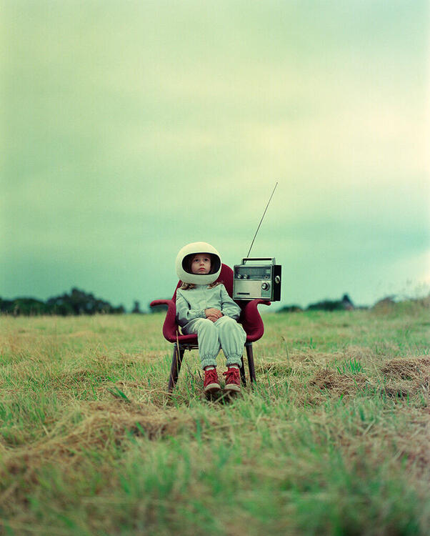


 1 point


Important Information
By using this site, you agree to our Terms of Use.
Account
Navigation
Search
Configure browser push notifications
Chrome (Android)
- Tap the lock icon next to the address bar.
- Tap Permissions → Notifications.
- Adjust your preference.
Chrome (Desktop)
- Click the padlock icon in the address bar.
- Select Site settings.
- Find Notifications and adjust your preference.
Safari (iOS 16.4+)
- Ensure the site is installed via Add to Home Screen.
- Open Settings App → Notifications.
- Find your app name and adjust your preference.
Safari (macOS)
- Go to Safari → Preferences.
- Click the Websites tab.
- Select Notifications in the sidebar.
- Find this website and adjust your preference.
Edge (Android)
- Tap the lock icon next to the address bar.
- Tap Permissions.
- Find Notifications and adjust your preference.
Edge (Desktop)
- Click the padlock icon in the address bar.
- Click Permissions for this site.
- Find Notifications and adjust your preference.
Firefox (Android)
- Go to Settings → Site permissions.
- Tap Notifications.
- Find this site in the list and adjust your preference.
Firefox (Desktop)
- Open Firefox Settings.
- Search for Notifications.
- Find this site in the list and adjust your preference.