Leaderboard


Popular Content
Showing content with the highest reputation on 03/21/24 in Posts
-
5 pointsIs that my Alien chestburster or Quatto holding my tiny beer while my beard powers my headphones? Thanks for the good wishes all. My ear is doing very well and I am feeling grateful about that. Penny and I had a quiet day but I went out of the local tavern for an excellent broasted chicken dinner and a couple of Two Hearted Ales. Cheers friends!5 points
-
Tell Mama by Etta James (1968) https://album.link/i/1371791759 Example: Just a few tracks that were not great for me. But the rest of the album kicks ass (like the example). Was over so fast that I had to pull this. At Last! by Etta James (1961) https://album.link/i/1440838775 Example: Everyone knows the title track... Much more the classical and strings versions, but man does it highlight her singing.2 points
-
I wonder if they would double as musical instruments. (fart) (tweet)1 point
-
1 point
-
1 point
-
1 point
-
1 pointA very happy birthday to you, Al. Sorry to hear about the ear (punny, I know) but glad to know that you're on the mend and enjoying your day.1 point
-
1 pointHappy Birthday Al, wishing you a safe ( Non Boeing?) aurally uneventful flight home. oh, and I'll just leave this here. "Al is a man. Al has a beard. Al likes beer. Al likes Pliny the younger. Al likes cocktails. Al is working his way through the 100 cocktails of the New Anvil List. Al is a headphone enthusiast. Al is an audophile. Al likes woodworking. Al is a retired lawyer. Al has been making maple syrup. Al is also known as Voltron, Defender of the universe. Generate a Photorealistic Picture of Al enjoying his birthday, *for entertainment purposes only."
 1 point
 -
1 point
-
I've mentioned that much of MV live takes place on Facebook groups (much to my chagrin.) There's 3 major ones: Islanders Talk (invite only, must be an MV resident, no politics allowed), Islanders Unfiltered (same, allows politics, reads like the staging area of the next January 6), and MV Stuff 4 Sale (what it sounds like.) In that last group I see all sorts of deals, and have listed a few things myself. I saw this yesterday:1 point
-
1 pointI am now in my fourth month of using the amp. The hissing went away 2 weeks ago. All by itself. Completely. Either the warming up was completed, or a miracle happened. Don't know. But I'm glad1 point
-
I also watched it and the documentary the bloody 100th right after it. My dad was a egineer on a B17 during WW2 so I had some interest in the show. I also got to fly in a B17 at a air show with my son at a air show at the air power museum on Long Island1 point
-
1 pointThis might be too crazy for me but why not go further. I happen to have a couple of 30kWh, 400V battery packs so a DC-DC converter and make it "portable"?1 point
-
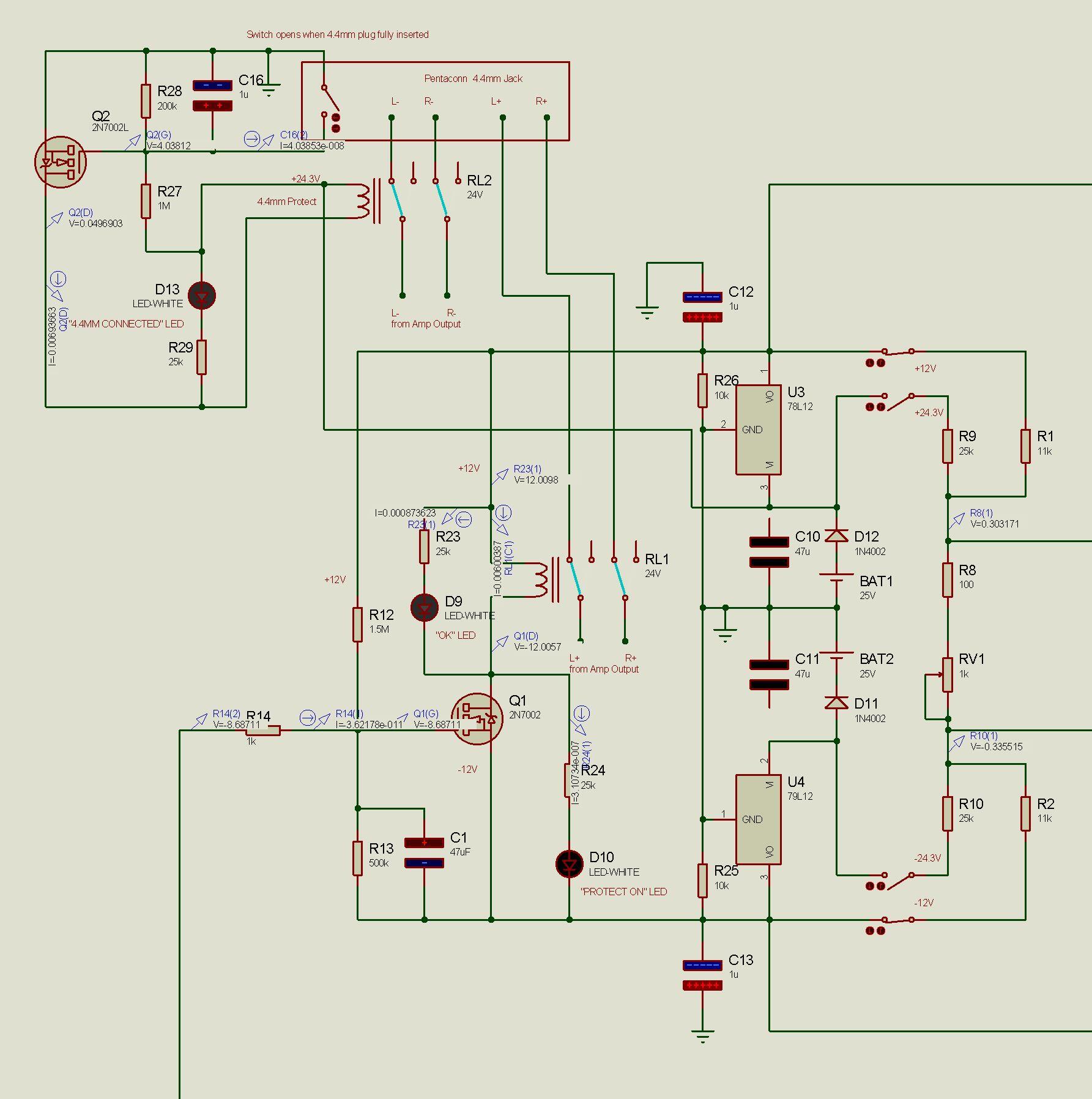
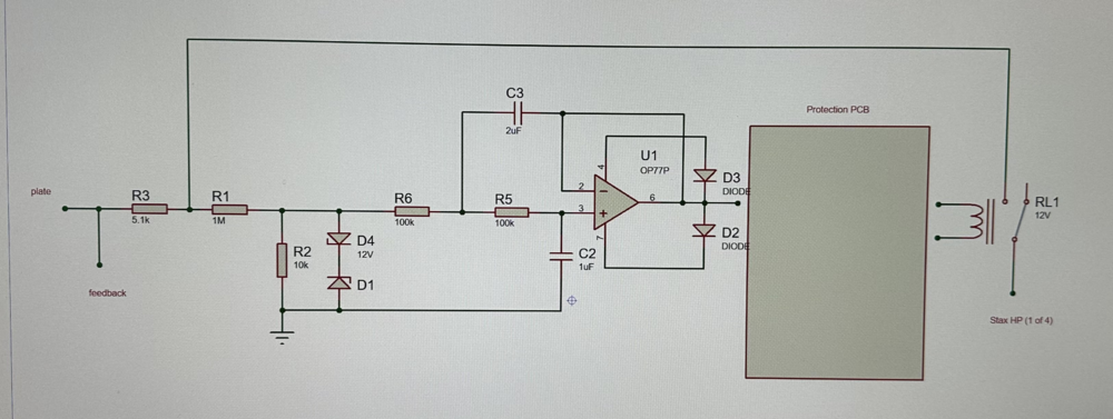
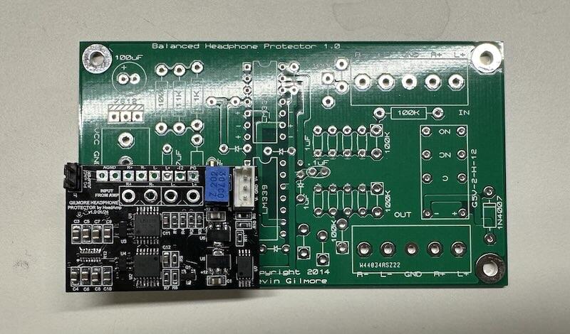
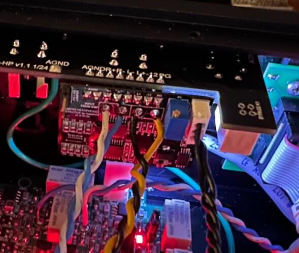
1 pointI'm going to try an electrostatic HP version of Kevin's balanced HP protector. I may keep all 4 outputs separate, using 1kV rated relays, which are usually single pole anyway. Plus this way each output could have its own status LED, which would show which of the 4 outputs (L+, L-, R+, R-) was triggered. Here is a preliminary idea:
 1 point
 -
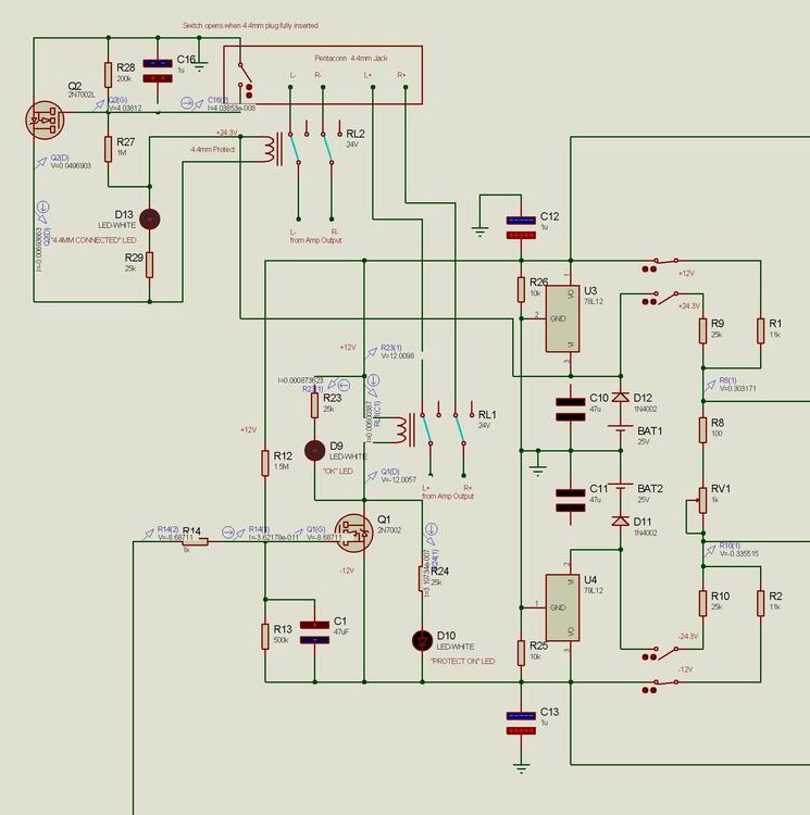
1 pointI made a SMD version of the Protector PCB for the CFA3, and after testing it this weekend I came up with some ideas for changes #1 - add blocking diodes in series with the power supply inputs. first thing I did was fry the V+ regulator by hooking up power backwards. other protection diodes for the regulators could be added, but I think they're less important #2 - add minimum load resistors for the regulators (R25, R26). I've previously noticed some 3-pin regulators can have an unstable output voltage if their load is too low. the resistors are so each regulator has at least a 5mA load #3 - option of getting DC voltage reference from the +/-12 regulators or the external supply. In this case, the +/-12 regulators could have as much as a 0.5V imbalance which requires hand selecting resistors to set the voltage reference (the voltage across R8 + RV1). if powering the protector with LT1021 referenced GRLVs, the voltage is going to be within millivolts for both + and - references. You would install either R1 or R9, and R2 or R10. the PCB could also be designed to allow switching between the two for two different range options. one feature of using the GRLV / higher voltage supplies for the reference is if those supplies were to become damaged and start outputting a different voltage, the reference will probably be thrown off more than enough to permanently disable the output jacks until the problem is found/fixed. #4 - added RV1 pot, the purpose is to adjust the range of the protection if it is too sensitive or not enough #5 - added dual indicator LEDs, for "Good" (D9/white) and "Protection On" (D10/orange). Not a bi-color LED, but 2 separate LEDs next to each other. The white "good" LED will be lit but very dim when the Protect LED is on, and the orange will overpower it. #6 - changed relay from 12 to 24V for 1/2 the current and to use more equal current from the +/-12V regulators #7 - added 4.4mm Pentaconn jack short protection. The 4.4mm jack has a switch in the back that only opens when the plug has been fully inserted. The relay keeps the L- and R- pins disconnected, which is every other pin on the jack, until the plug has been fully inserted + a .5 second delay, and then instant release of relay when the plug starts to be removed SMD version & in CFA3
 1 point