JoaMat
-
Posts
1,558 -
Joined
-
Last visited
-
Days Won
16
Content Type
Profiles
Forums
Events
Everything posted by JoaMat
-
Who is the producer?
-
R11 determines the current through LT1021-10 which needs 1.1 mA at 25 degree C. Choose R11 value accordingly. For +/-500V sections; R11 = 400K gives 1.4mA and 0.8W.
-
Jolly good work! Thank you for the excellent PDF document. Lots of interesting stuff there.
-
Happy Birthday!
-
I think you can say the last stage of mini T2 is Q8/V3 and Q9/V4. The signals come via R11 and R12 to base Q8 and base Q9.
-
Happy Birthday!
-
I don’t think mini T2 works the way you think, micon21. Here is an excellent description how to build the original Blue Hawaii. There is also a nice explanation how it works. Mini T2 works mainly as the Blue Hawaii does. Read the article (I read it several times – have slow brain) and I think you will get a better understanding how the dots are connected. Good luck and keep on with your good work.
-
R43,44 are the feedback resistors and R7,8 are the lower tube cathode resistors. LTspice simulation indicates that they all determine the gain of the amplifier. 100K and 100R, as in the original schematics, gives a gain of roughly 1000. With 270K and 2K resistors LTspice indicates a gain of 140. The resistor changes you have done will not change DC voltages at the small tube pins. Maybe your trouble is somewhere else than at the feedback and cathode resistors. But don’t give. It seems you are more than competent to build a mini T2 and, even more important, to fix it if it’s broken. I guess you will have a fully working mini T2 sooner than you now think.
-
If +220V out from PSU you should have +200V on pin1 and 6 and +69V on pin 2 and 7 upper small tube. Lower small tube should have +71V on pin 1 and 6. Your -334V on EL34 Pin 8 seems to be too high, I would expect something like -400V or lower. This, of course, is in a perfect world. What supply voltages do you read on the amplifier board?
-
Thanks a lot, guys! I’ve had a terrific and quiet Birthday time with my wife and eldest grandchild - after a "hectic" Christmas celebration with our two children and their families with a half dozen grandchildren.
-
Merry Christmas!
-

and now for something completely different part 3
JoaMat replied to kevin gilmore's topic in Do It Yourself
The answer is No. It doesn’t work. The bottom line is I’ve big trouble get it working. So, I'll put my version of a Tube Hybrid on hold. Probably for a looong time.
-
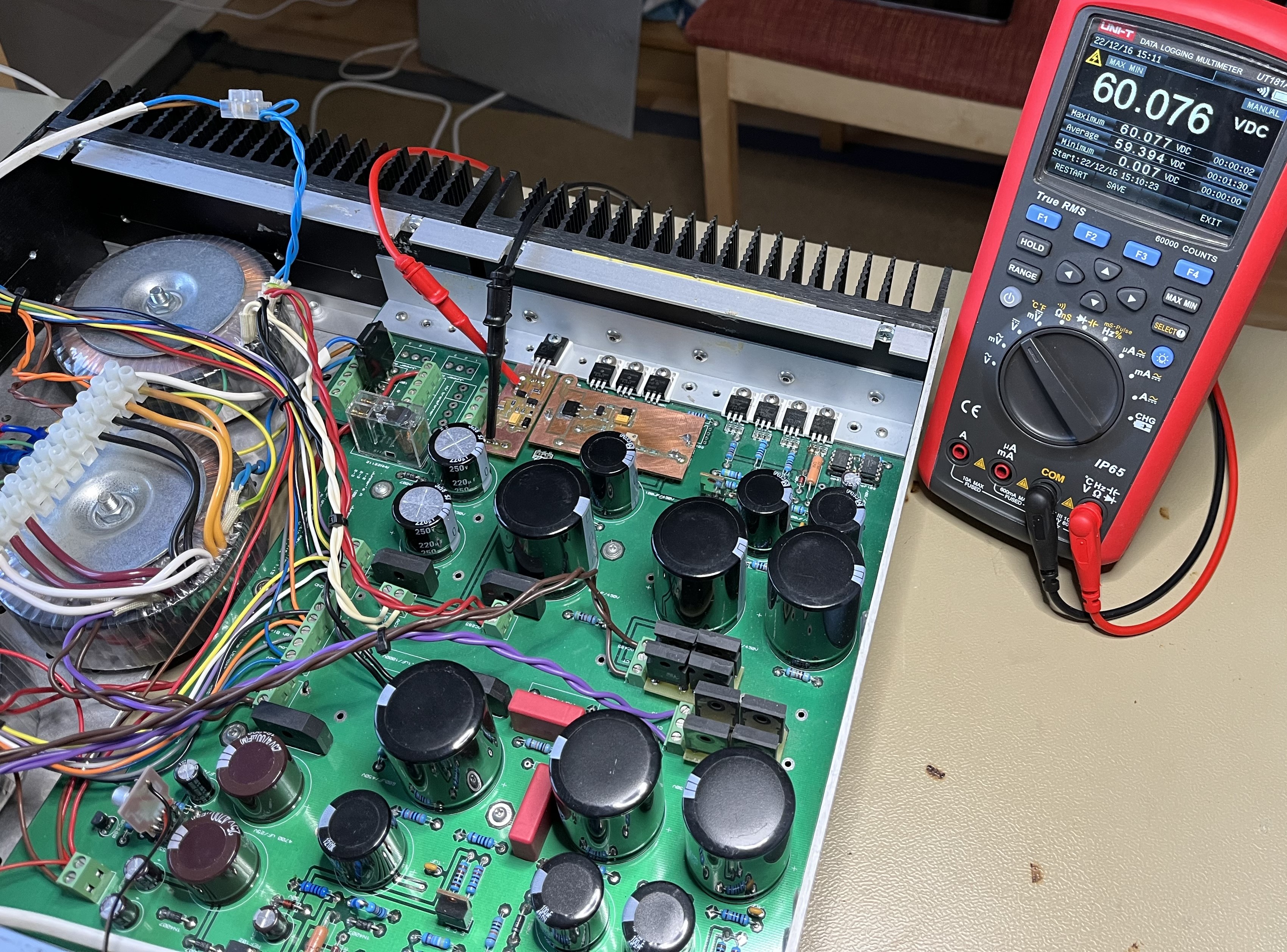
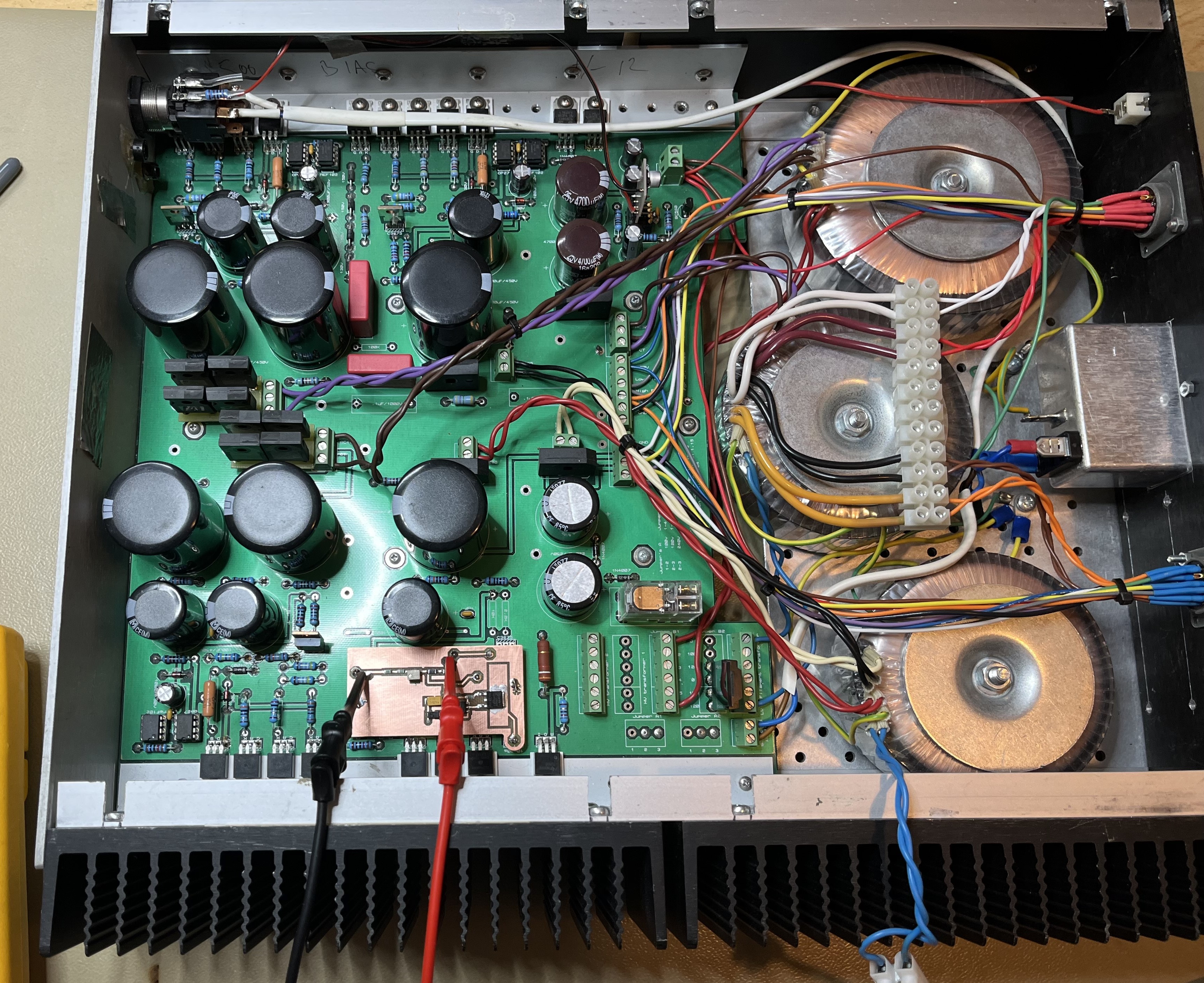
Thanks for posted picture Kerry. Your astonishing builds are very inspiring. In the original T2 PSU the 60-volt section is regulated by LT783 which I think is good enough. But inspired by Kerry I did this little fellow (the small copper clad with test leads) to replace the LT783 regulator. Connected to main board via three connections. Works like a charm – knock on wood.
-
Thanks a lot for all your inputs, Kerry and simmconn. Now it seems I’m back on track (knock on wood). Since “reflowing” the board and a new HN4A51J the PSU has been working for almost 24 hours with several on/offs. Voltage is stable, decreases some tenths of a volt from cold and than bang on the intended 150V. After some struggling, I managed to measure the three faulty HN4A51J. All Q5:B are unknown components on the tester while Q5:A are PNP with hfe of 4 or 5?. Now the angels are singing on my modified T2 with EML tubes.
-
Thanks Kerry. I just had to wait four hours for it break down this, the third, time. Same procedure as last time – replaced HN4A51J. Also reflowed all solder points – hot air – hope this will help...
-
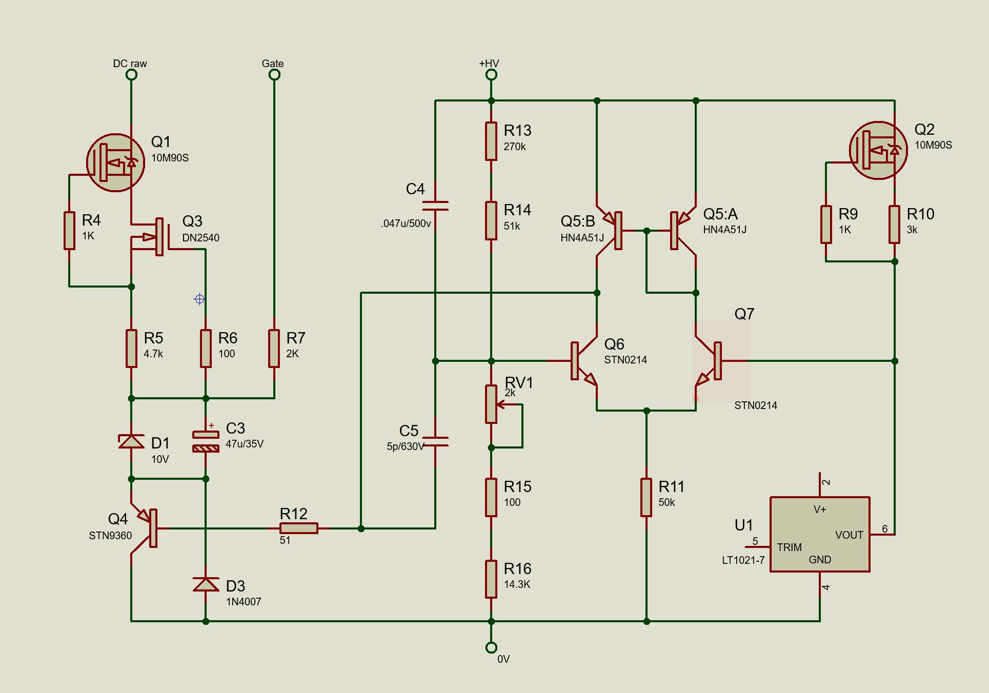
Here a schematics. Four connections to main board. The raw DC is taken before the two 10m90s current limiters. Better would be after the limiters but no free hole for it. Works like a charm I wrote. Yes, charming it is when it works. When it suddenly stops working and give 13V instead of 150V – that is more annoying than charming. It has happened two times so far since my last post. Not sure what’s wrong but I change Q5 (dual small PNP) with a new piece and then it works for couple of hours. Now I’m just waiting for the next breakdown. Suggestions what might cause the problem are welcome!
-
Almost a year has elapsed since I reduced the 300V section to 150V. The amplifier has worked well, and I haven’t noticed any sonically differences. So, some time ago I decided to make the same change on my modified T2 and its original T2 PSU we have at our summer cottage. But unfortunately, it was not possible to bring the voltage down to 150V. 190 – 200V was the lowest I got. I’ve had a Golden Reference power supply for the T2 in mind for a long time. Now I had to do something the get the desired 150V section with the original T2 PSU… Made a daughter board with GRHV regulator for the original T2 PSU. Works like a charm.
-
and now for something completely different part 3
JoaMat replied to kevin gilmore's topic in Do It Yourself
My impression is that this is intended to be a Muscle CFA3. You probably want 3U – at least. No V12 engine in a Volkswagen Beetle. -
and now for something completely different part 3
JoaMat replied to kevin gilmore's topic in Do It Yourself
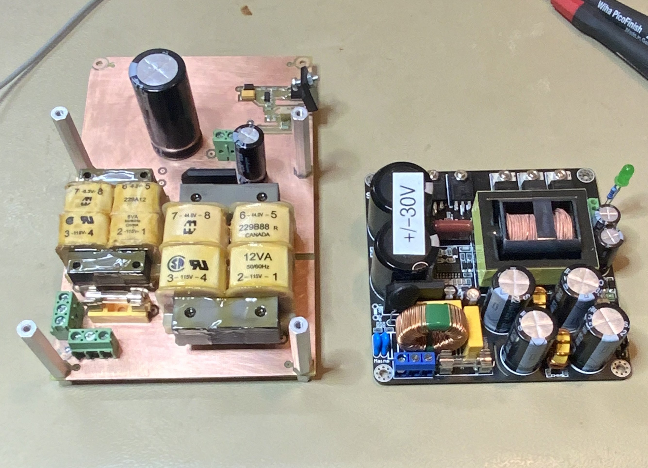
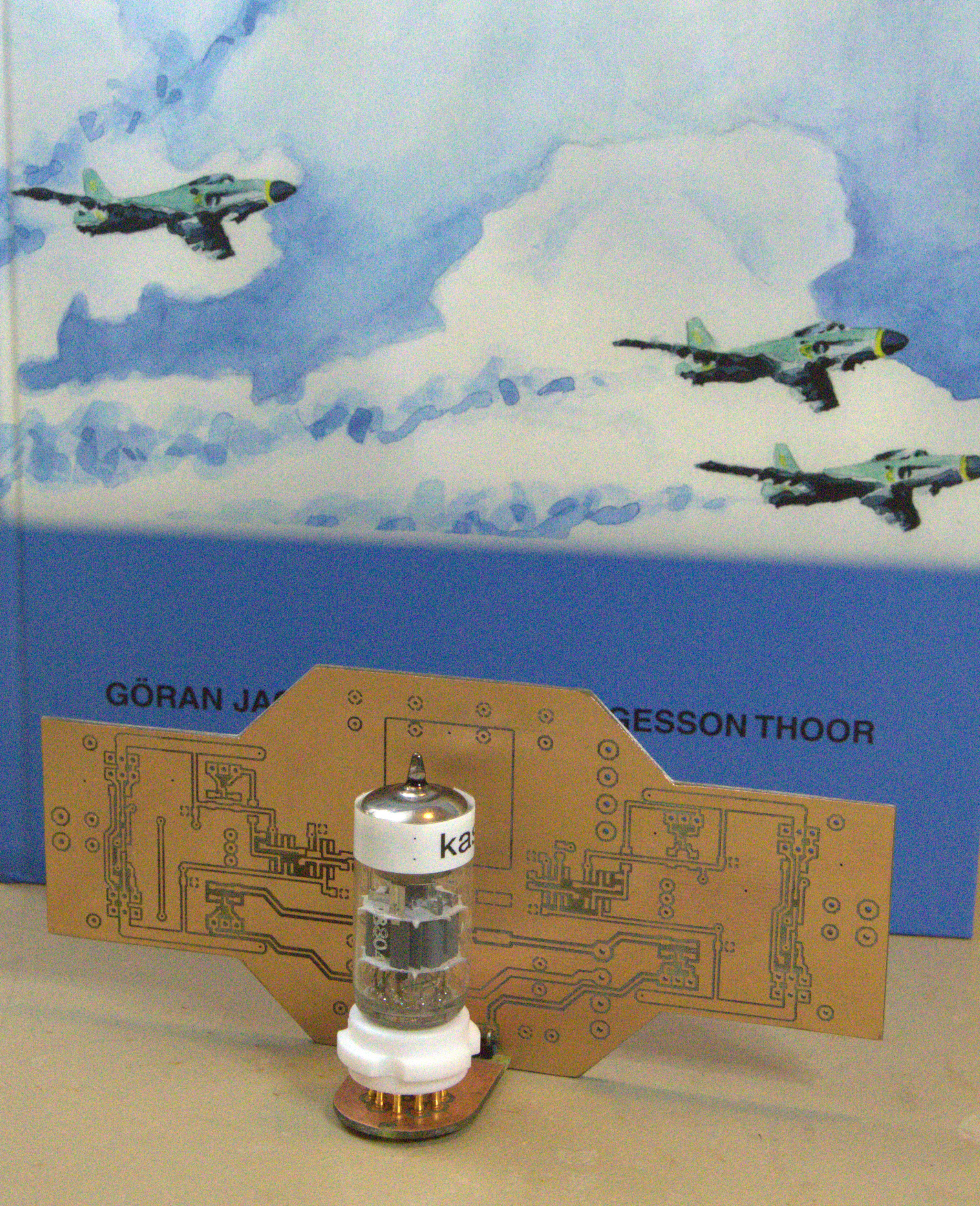
Some progress with Tube Hybrid(something). PSU; left – Board with filament transformer and transformer for GRHV style regulator (+100V). To the right is Connex SMPS, put it in top of the first board and you have PSU with 6.3VAC, +100VDC and +/-30VDC. Amplifier board with a tube daughter board. The required -5V is done on the amplifier board with a smd 7905 and a few capacitors. Will it work? Who knows?
-
and now for something completely different part 3
JoaMat replied to kevin gilmore's topic in Do It Yourself
I guess those big things stand some heat. Why not just remove the throttle plate (vbe multiplier)... and feel the speed. -
and now for something completely different part 3
JoaMat replied to kevin gilmore's topic in Do It Yourself
Thanks. According datasheet they are to3p devices - a bit bigger than mjf1503x.