JoaMat
High Rollers
-
Joined
-
Last visited
Everything posted by JoaMat
-
-
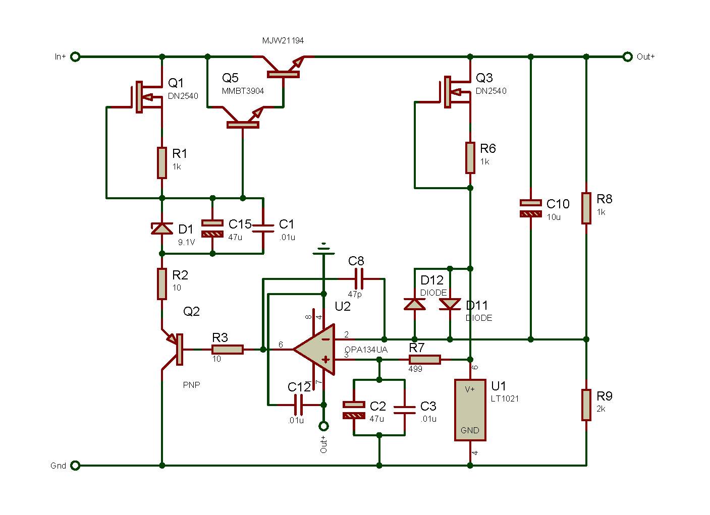
LTspice indicates a need of another 3 V unregulated. Plus more diode switching noise. Still a golden reference device or is it a silver line thing?
-
Thinking loud. What if a simple CCS north of the 9 volt Zener as below? Will certainly make a tiny smd version layout looking cleaner.
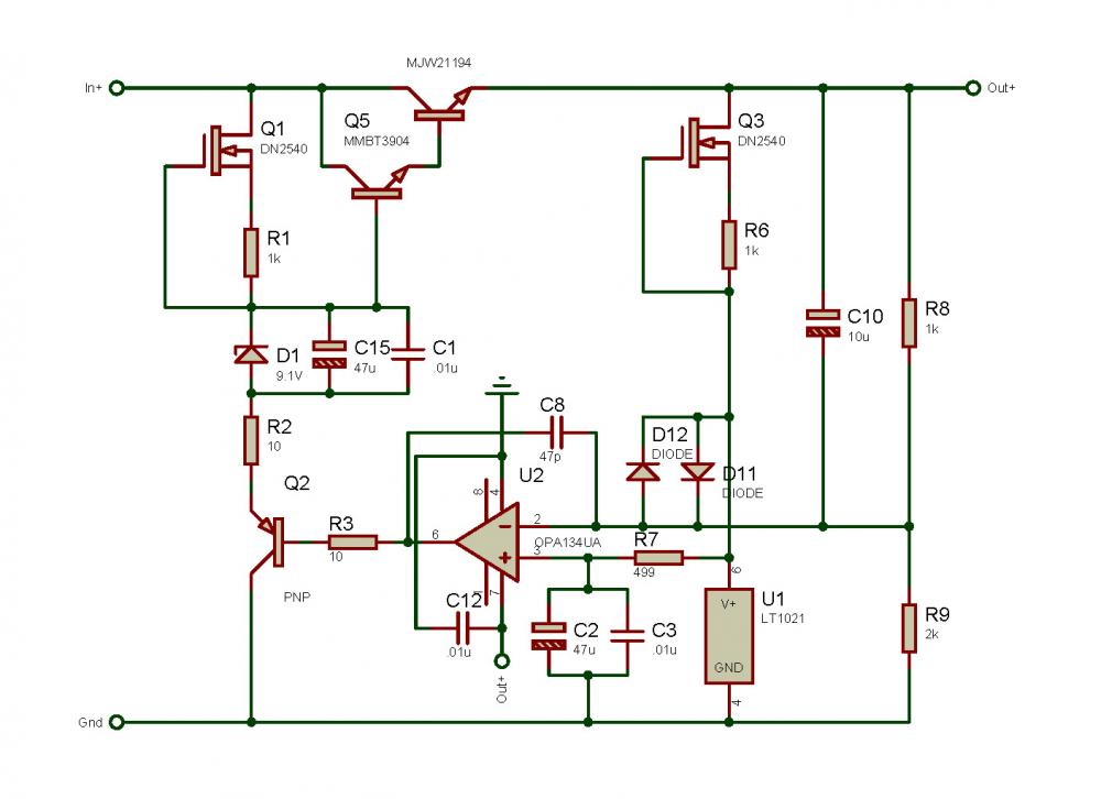
-
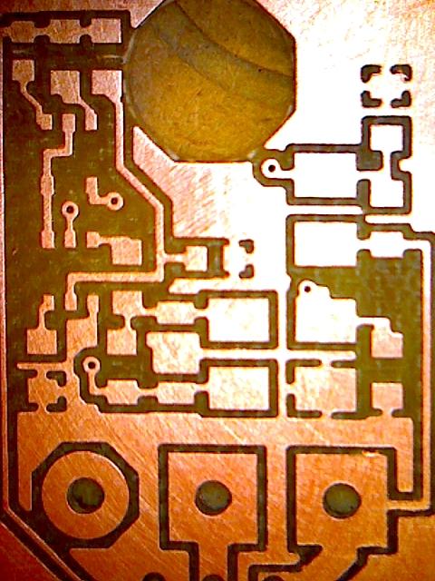
Milled this today – negative regulator. Shot by USB camera approximately magnitude 20. Using a 15th end mill, minimum clearance between pads, traces etc. is 16th. There are 5 vias 12th and they actually hit the bottom pads quite accurate. CNC machine is a fantastic gadget
-
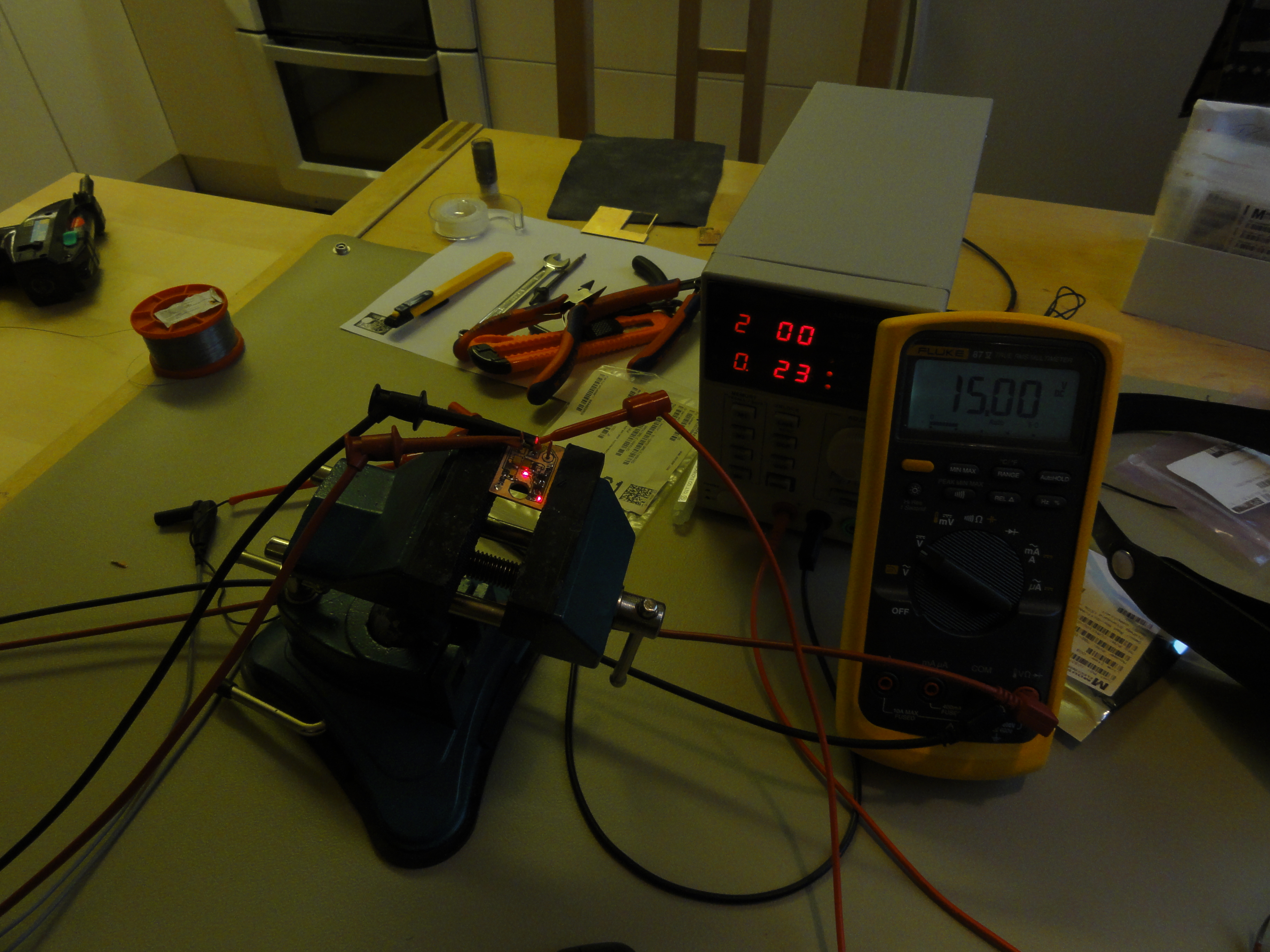
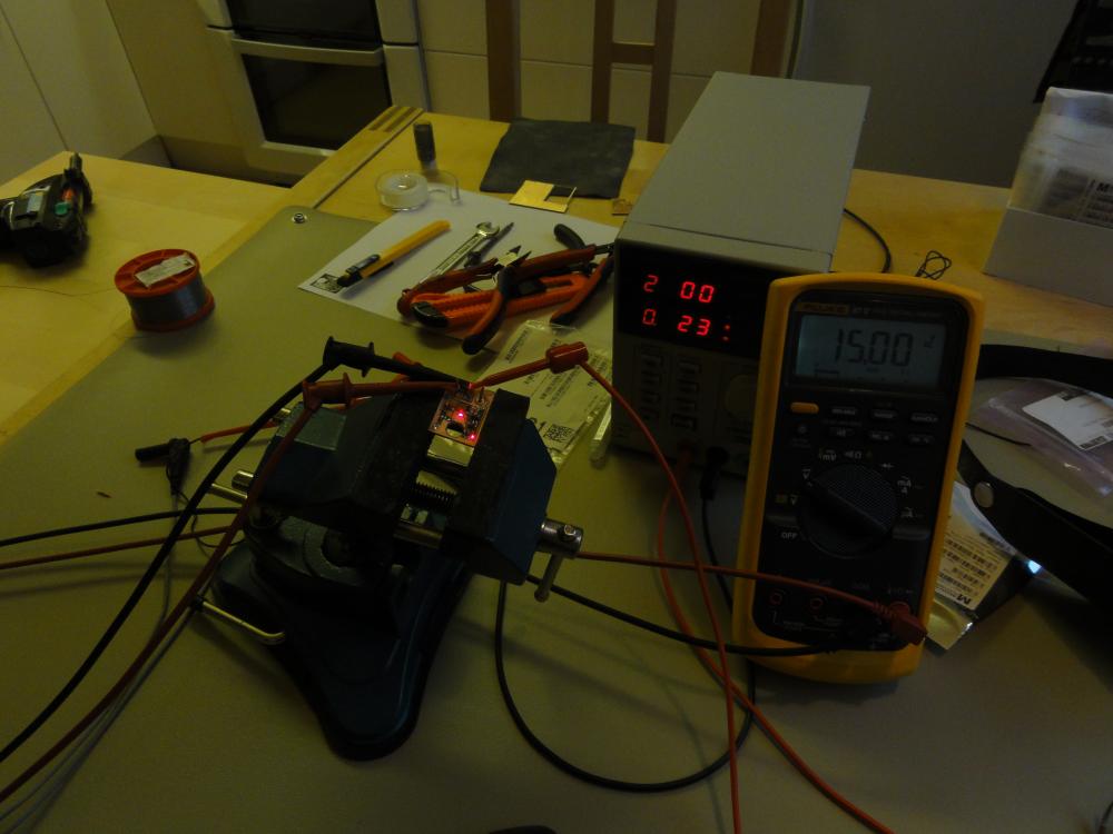
Did this today. Positive golden reference regulator. I managed to make a Kerry device in my kitchen but I think he is pushing the envelope now. I’ll try to make negative regulator as well and if this succeeds I’ll put them in a T2 PSU. Dark picture so you can see the small red LEDs on the board. Hope the small GRLV hit the market soon.
-
Great work! Reason for KST42/92 replacing PBSS4140DPN? - need for higher collector-emitter voltage?
-
470R resistor, isn’t that the grid resistor? If so, is 2 W really necessary? From simulation I get some 2 – 4 mA through the resistor. In my Grounded Grid with mostly surface mounted devices I use 0805 chip as 470R - 1/8W and they seem to work.
-
Law of nature. You always need a sufficient transformer.
-
Oh, sorry. Too much Amarone. Happy New Year to you all!!!!
-
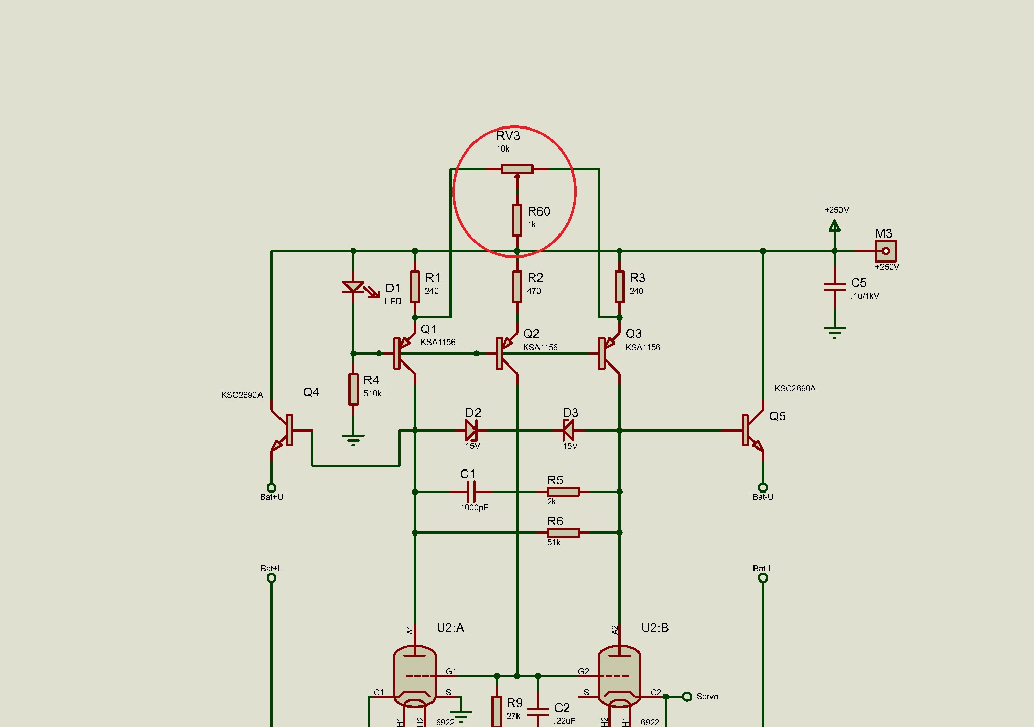
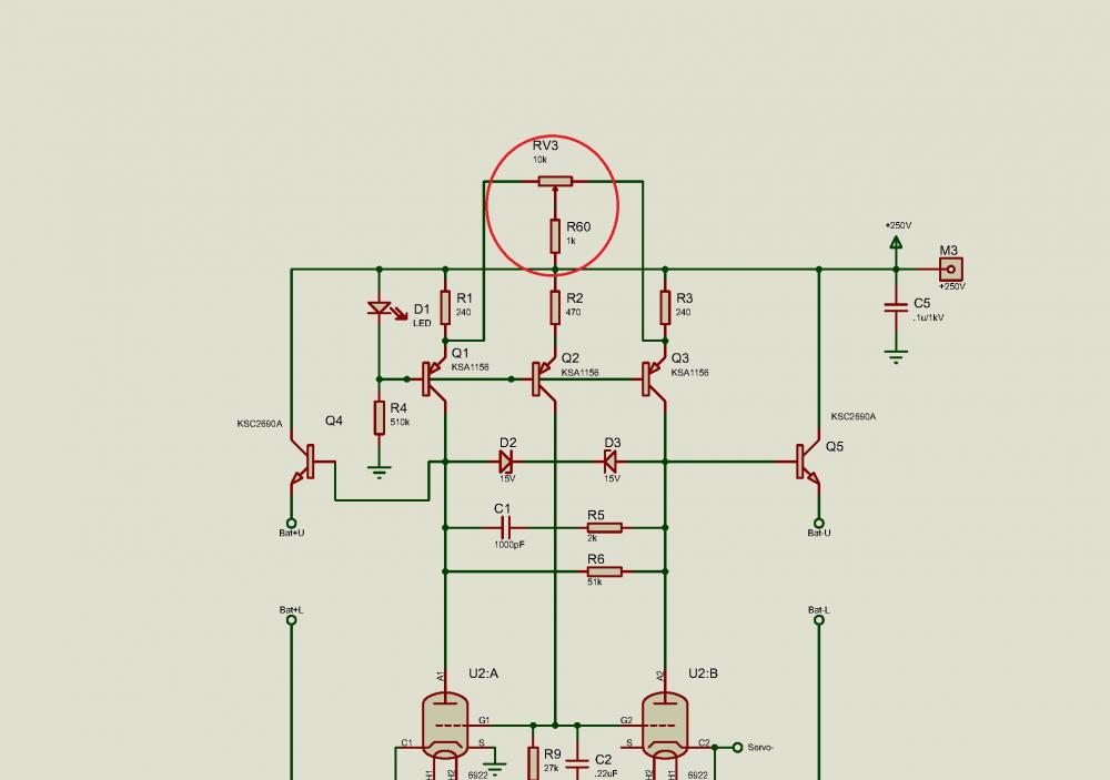
If the pot you are asking about is same as RV3 in schematic a few post earlier then; With 240R as in the original DIY T2 the current theoretically is 5.1 mA. Adding 10K pot and 1K resistor with pot at mid position give 5.2 mA each CCS. Pot at end point gives you 5.1 respectively 6.2 mA. Just increasing the pot value won’t change the “current range”.
-
I’m very much interested.
-
Happy Birthday!
-
-
-
-
All right, I rather prefer to open you gerbers in Proteus and save them as pdspnl files – works great. Thanks a lot for all work you have done!
-
I use Proteus v8.5, isn't that the software you are using? I guess you are able to open gerbers you made yourself. Can it be some software setup I've missed?
-
When I try to open gerbers, probably of newer version, in Proteus I get warning about “Bottom SMT Paste Mask” and file won’t open. After deleting corresponding line in the readme file it opens nicely in Proteus. What might the reason be that it won’t open without delating that particular line in readme file.
-
-
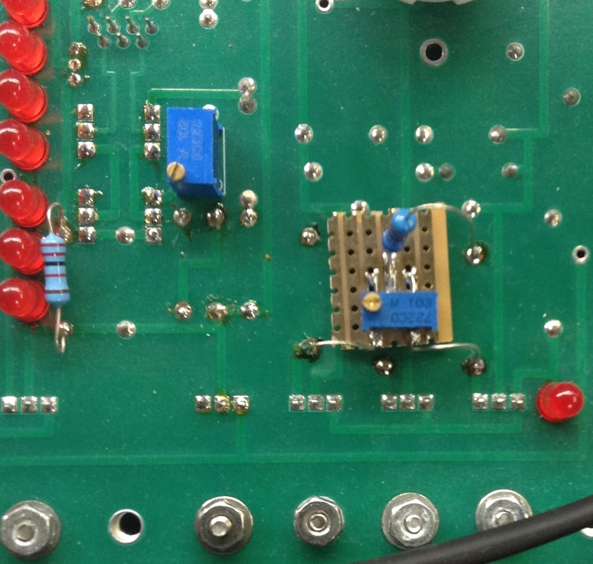
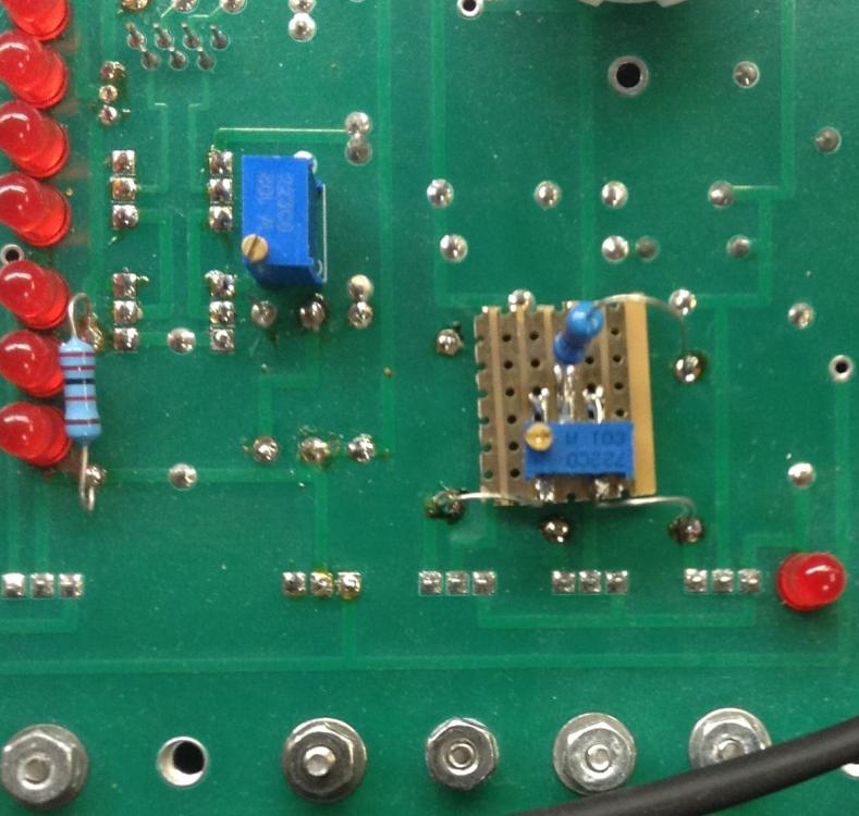
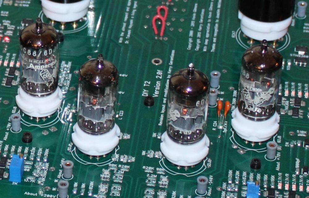
This is how the small board with trimmer and resistor looks like. I do think the T2 amp board by Kevin is a very good one. Easy to build, just put the right component in right position, solder properly and then you are done. If something goes wrong it’s possible to work on the board. And it's also a terrific board for experiments, tests, modifications…...
-
Nice, manual control seems to work well.
-
No, schematically like this: added RV3 and R60. I got it balanced when current was 5.1 respective 5.8 mA. When upper and lower tubes changed place I had to reset back to original setting – the unbalanced like of disappeared.
-
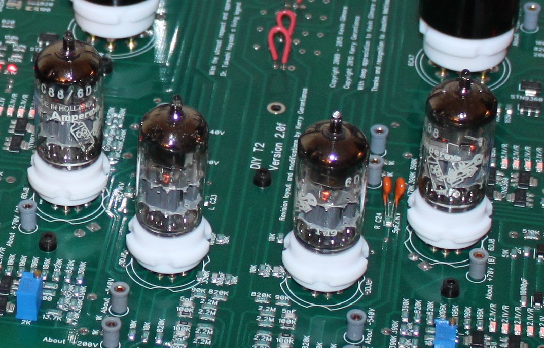
Finally I did notice…… Four Bugle Boys. Ref. link Nice!
-
No, trimmer is replaced by a resistor long time ago. The 10m90s current source is connected to ground and set to 1mA. Today I modified the input tubes current sources with a trimmer like T8000. Also changed the servo, using single OP tied direct from output via resistor to one of the lower tube cathode. One channel had more than 200 volts unbalance with no servo and both batteries set to 740 V. With the trimmer I managed to get outputs balanced – have been within +/- a couple of volts for half an hour now (servo disabled)….. to be continued….
-
Moving the servo to the cathode would that be a good idea?