-
Posts
8,568 -
Joined
-
Last visited
-
Days Won
7
Content Type
Profiles
Forums
Events
Everything posted by Pars
-
RIP Cecil; and RIP Michael... tragic Sent from my iPhone using Tapatalk
-
Yes, those would work nicely as well. Just be careful in that even though these share the same 7-pin package as the 2SJ109/2Sk389 Toshiba JFETs, they are not pin compatible. Therefore, a THAT340 adapter made for one will not work for the other. 2SA1349/2SC3381: BCE-ECB 2SJ109/2SK389: DGS-SGD Sent from my iPhone using Tapatalk
-
Very nice Steve (and Milo)! So you like Arm-R-Seal? I've always used Varithane. Is something like Arm-R-Seal what you would recommend for a natural cherry finish? Thinking about building a Salamander Synergy clone, but need to draw up plans for it.
-
If you buy the duals in the linear devices, you can just go with what you get. The 2 devices in package are matched pretty well, and Kevin said that CCS will take care of the N-P differences you have. The ones I bought from trendsetter (LSK489/LSJ689) weren't too bad.
-
Sort of along the lines of the last portion of your post Birgir, I was pretty horrified reading this thread... http://www.diyaudio.com/forums/tubes-valves/320948-repairing-hi-preamplifier.html
-
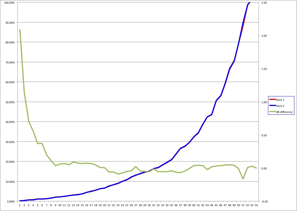
Partsconnexion replaced the pot with one they apparently hand selected. I supplied my data and graph above to them, and did let them know I had soldered it in. I returned it. The replacement arrived today so ran numbers on it in the same manner as before. It looks much better:
-
Thanks Jim, just what I was looking for! I already have one GRLV plus built, so I'll start with that (and maybe build a 2nd for dual mono). As mentioned, the Salas shunt regs are on the boards, so if I decided to switch to those, all I have to do is populate them (and build a raw dc supply to feed them).
-
Sure, if its no trouble. The more reading, the better
-
Thanks Steef. Yes, those are helpful in getting a basic understanding of the differences.
-
My previous query(ies) may have gotten buried. Given the somewhat religious fervor this topic seems to generate on other forums (without much technical justification for the most part; just assumption), I would like to know people's thoughts on this. My take from other reading seems to be if not shunt then you are a) a dumb ass, or b ) you just don't appreciate the best. I did read a critique/analysis on topic that discussed shunts presenting a more uniform impedance to the load, but then went into a discussion of a push-pull relationship via a shunt, versus a push only relationship with a linear reg. My specific interest is in a Salas shunt vs. GRLV plus for a phono stage, but a general discussion is more than welcome, if for nothing more than my education
-

and now for something completely different part 3
Pars replied to kevin gilmore's topic in Do It Yourself
Maybe the schematic is missing a connection point, but it appeared that Q9/Q11 are biased solely by the input? At any rate Jose, it appears you are running a balanced CFP2? If so, if it were me, I would front-end this with a ubal->bal board, and use JFETs as the input stage for that. It will be a) transparent, and b ) give you flexibility on using SE sources as well as balanced. Well, transparent unless you are one who can hear a) plating on connectors, b ) teflon vs. cotton vs. air vs. any other form of dielectric known to man, or c ) some form of crystals within 1 mile of your listening environment, or d) grass growing. Hate how the forum software turns a "b)" into a smiley -

"Monolith Liquid Platinum Headphone Amplifier by Alex Cavalli"
Pars replied to Kattefjaes's topic in Headphone Amplification
I submitted a question regarding this item on Monoprice... Why? Cavalli doesn't really know what he is doing. I would avoid this amp like the plague. -
That's really a disguised silver dollar there, isn't it Kerry Very cool! Now, tell me what these will do?
-
Paid, thanks Steve!
-

and now for something completely different part 3
Pars replied to kevin gilmore's topic in Do It Yourself
My take: I’ve only listened to either of these with orthos (modded fostex t50rp). I always found the Senn hd6xx to be too syrupy for my taste. I’ve never listened to the HD800s (I know Kevin really likes the ss Dynalo with these). This is comparing an SE CFP to a balanced SS Dynalo. First off, I don’t find the Dynalo to be more musical than the CFP. The CFP handles the orthos better, particularly in the bass. The CFP is neutral, though slightly darker than the Dynalo, which might just be a reflection on it being able to drive the orthos better with higher current capability. The CFP is using a single GRLV @+/-30V; the Dynalo also uses a single GRLV @+/-20V. Edit: I didn’t mention that the Fostexes are wired balanced, so the SS Dynalo is SE in->bal out Sent from my iPhone using Tapatalk -
This probably got buried in my post: No one has an opinion on shunt vs. linear reg for a phono stage? Specifically, Salas shunt vs. GRLV plus? Thanks for any thoughts! Sent from my iPhone using Tapatalk
-
Happy Birthday Tyler! Sent from my iPhone using Tapatalk
-
Thanks Ryan! Maybe I'll take you up on that once I have it built (kinda). This is set for somewhat specific loading for an AT ML440, so I would want to match it somewhat to your cart. I'll pm you when I have it more or less done and we can go from there. I haven't had a turntable setup in years. My table isn't exactly up to HC standards either (Thorens TD320).
-
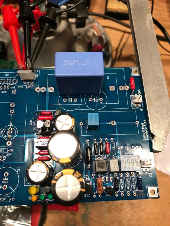
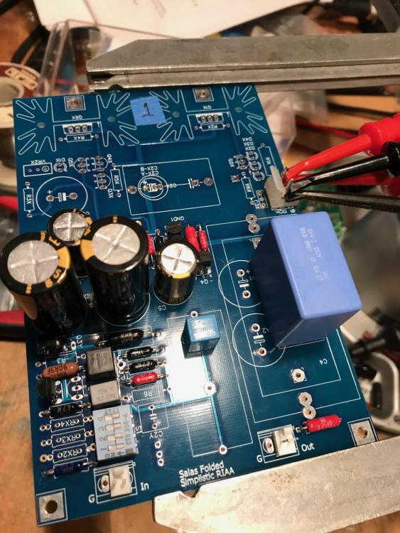
Thanks Marc. Yes, I'll take one. Me: Salas Folded Simplistic Phono stage. I did my own board layout (in Diptrace), based on the diyaudio board, but made a few changes. I built these with parts I had laying around (other than the 2SK369BL quad from Tea Baf on diya and 2SK117GR JFETs which MA Santos was very kind to send to me, as the ones I had weren't high enough in IDSS). Resistors are a combination of Holco 0.1%, PRP, and for values I didn't have, Welwyn RC55 0.1%. I'll probably replace some of the PRPs with Welwyns as well. The caps I had around (MKP1837 and BC MMKP 383), but will probably replace these with some Mundorf Supremes. Target case is a Modushop Slim Line 1U (team single chassis). Both boards worked fine on initial power up. I am currently leaning towards powering these with either 1 or 2 GRLV plus boards set at 35V (have one built and tested). If anyone has a good reason to instead use the Salas shunt regs (which I have on the boards, just not populated), let me know what you think. I know a lot of people ooh and ahh over shunt regs, but I'm not quite so sure they are automatically better than a good linear regulator such as the GRLV. Salas' do have a good reputation however.
-
I guess I'd be interested in one of the boards. PM me with details. I looked at the Muffsy website and found the hifisonix project, but didn't see a BOM. Do these come with the components?
-
I might be interested in one of these if you have any left Marc. Or borrowing yours... Where did you get the cute little case for this? Sent from my iPhone using Tapatalk
-
The jpg are the only schematics that Kerry provided for the mini. I may draw a set up if I have time, as the legibility of these leaves something to be desired. The ss Dynalo (and Dynahi) will handle any combination of input/output. 1) balanced in/balanced out 2) single ended in/balanced out 3) single ended in/single ended out 4) balanced in/single ended out If you opt for only a balanced output jack(s) you won’t be able to provide single ended out without some pre-planning. The mini as Kerry has defined it provides both a 4-pin balanced XLR and a standard 1/4” stereo single ended output. Single ended input loses ~6dB compared to balanced in. Sent from my iPhone using Tapatalk
-
The supersymmetry input section does unbalanced to balanced conversion. You can use either single-ended or balanced sources with this. For single-ended source, the - inputs should be grounded. You might try actually reading the thread... Sent from my iPhone using Tapatalk
-
Hi Gael, How long until you get the prototype? As for lead times, I guess I never asked when I was talking to CAM Expert, but I was under the impression that it would have been 2 weeks or less with them? John has ordered from them before, but shipping to Australia I'm sure takes some time I'm certainly no typeface expert. The fonts that John used in FPE Frontdesign were Asian 1 stroke (for the supersymmetry) and Euro 5-stroke for the Dynalo. He did do some manual kerning by doing the "D" and "y" of Dynalo individually and arranging the spacing. He used 10% incline to mimic italics. From your samples, I like the Hiragano Maru Gothic, but don't care for the Silom. I like the Gil Sans Bold but the all caps on the DYNALO is too much, particularly with that font. You might also look at Calibri or Futura if you have those (typical Microsoft Office stuff).


