Pars
High Rollers
-
Joined
-
Last visited
Everything posted by Pars
-
-
Pretty fucking desolate, at least so far...
-
Happy Birthday Mike! I hope you have a great one!
-
I don't know where you would put it, but the easiest separate PSU for the protector board only might be to use a pair of Meanwell 15V bricks as Kerry did for the mini Dynalo? The only problem with these is they don't always come up at the same time on power on, but that shouldn't be a huge problem for this application and could be solved with a short delay on the output. These you could wire straight to the AC L/N after the switch. The amps I've done I've never bothered with tieing the analog grounds to the chassis; just the IEC earth to chassis. You might put a ground loop breaker in between your star ground and the chassis connection.
-
-
Happy belated Birthday Grahame!
-
I was a bit floored that 6 ~42-45 minute episodes constitutes a season these days? I've watched half of "Season 3". Love the show but seems like a rather light season...
-
Started watching what I assume is a British produced mini-series on Netflix called Fool Me Once. Pretty good, has its problems but kept my attention as I streamed 4 episodes on Saturday night. About an ex Brit military helicopter pilot whose husband (also ex-military) is murdered. She then sees him appear on a nanny cam and strangeness ensues.
-
I know it wasn't a pentaconn jack, but a normal TRS jack, but this has been an issue for some time, with it causing a number of B22s to fail at meets when people would plug/unplug phones from amps which were on, and blow the output FETs in those. That sounds like a good solution Justin, as disconnecting the L-/R- would ensure open circuit on the outputs. I'm not a fan of the TRxS type plugs/jacks because of this issue, but I don't do or use portable equipment anymore, so doesn't really affect me. They make these things down to 2.5mm in a TRRS, which seems like a really bad idea.
-
-
Happy Birthday!
-
Happy Birthday Knucks!!
-
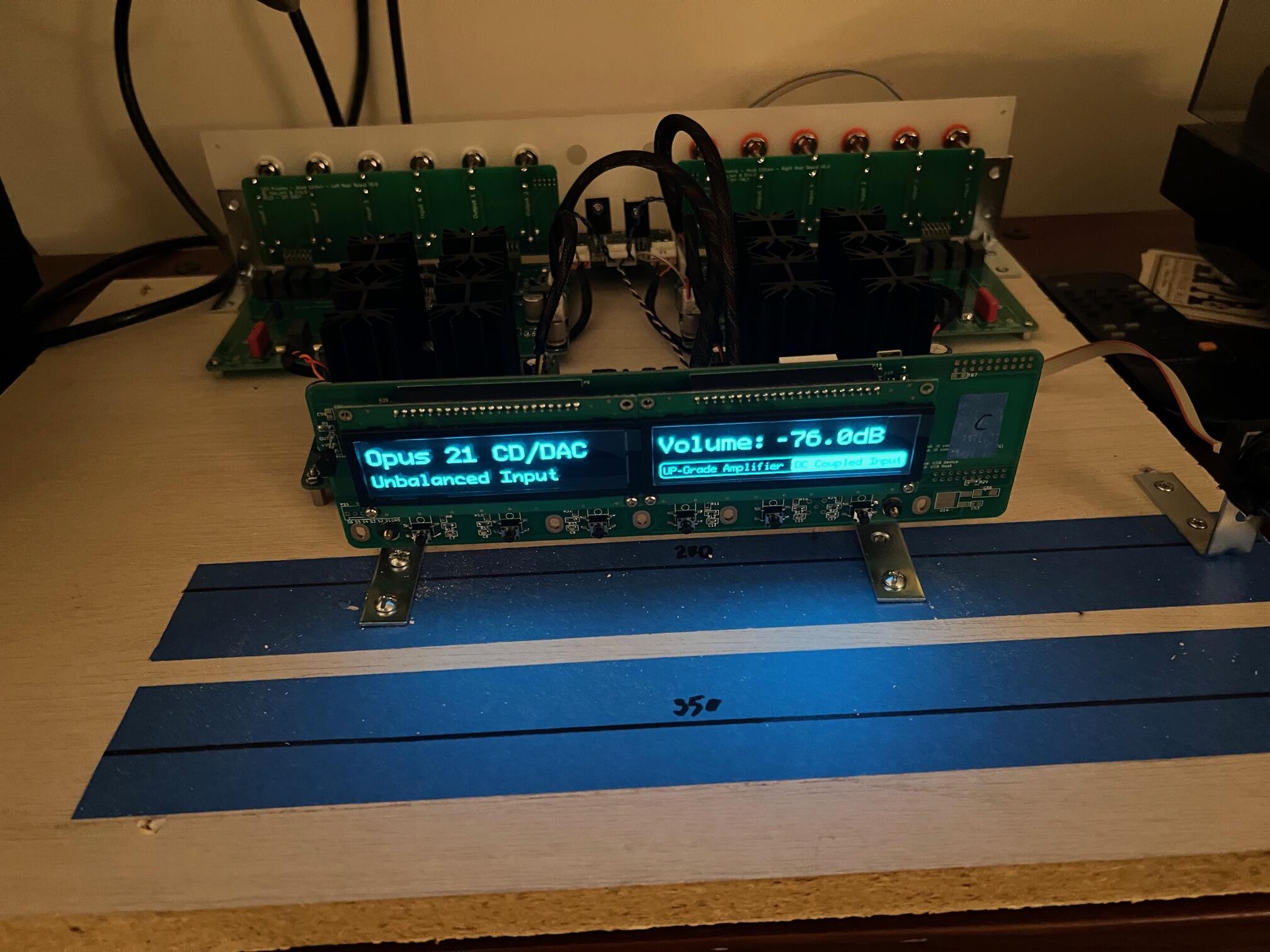
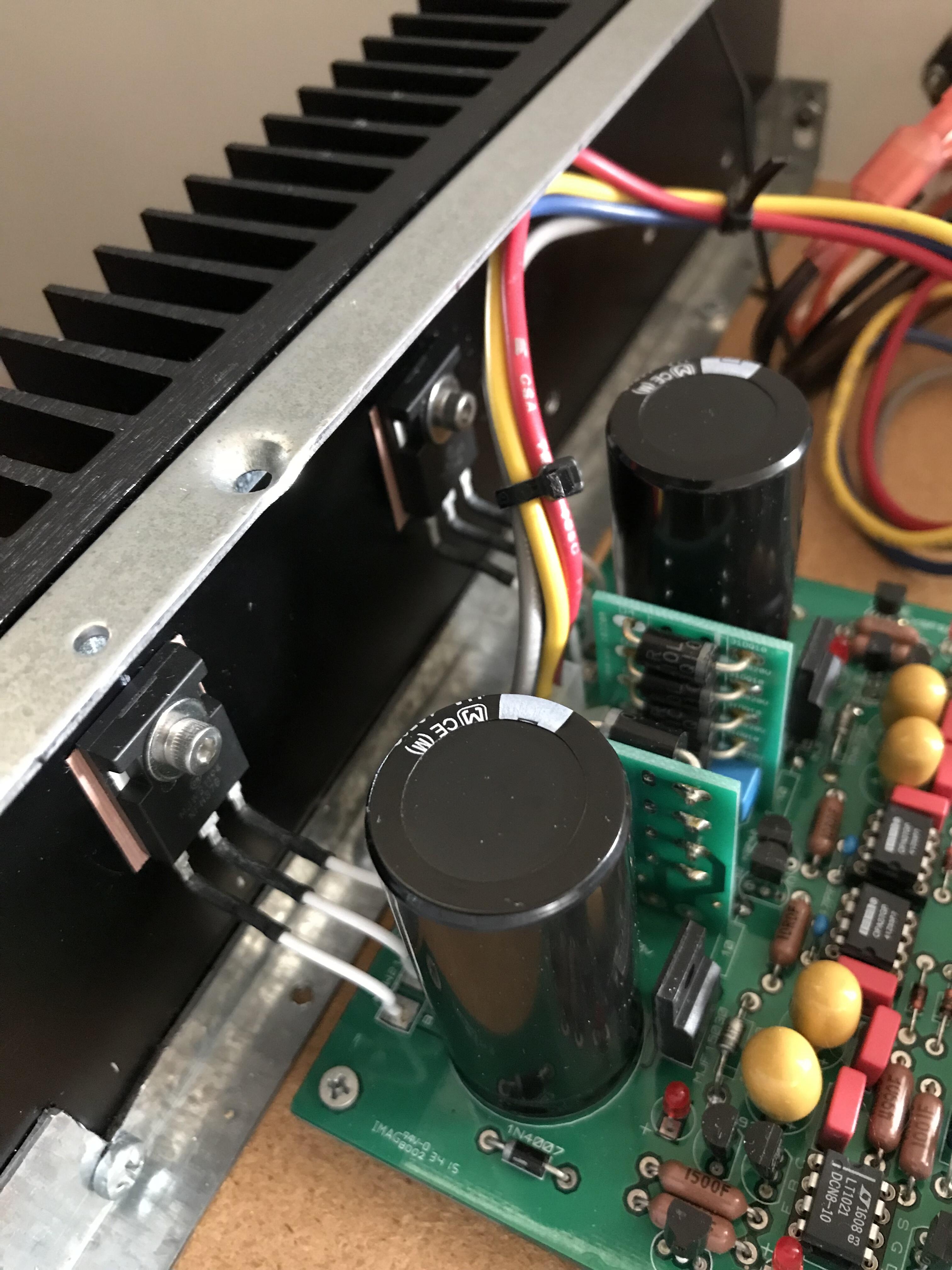
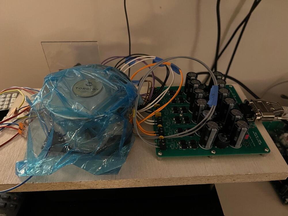
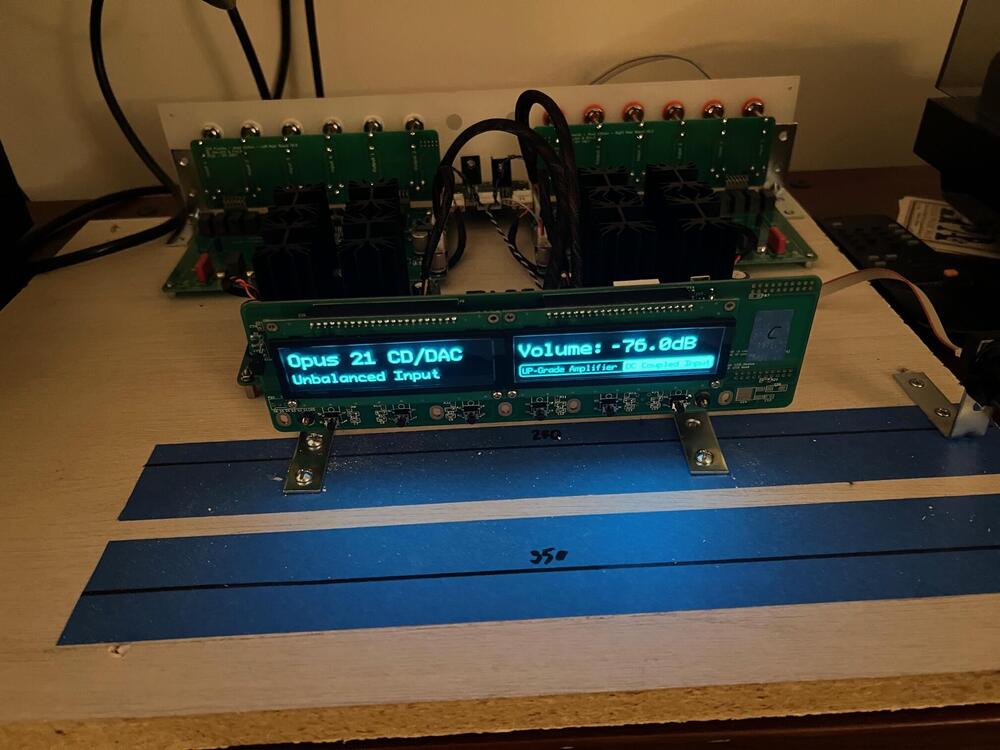
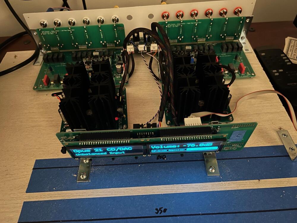
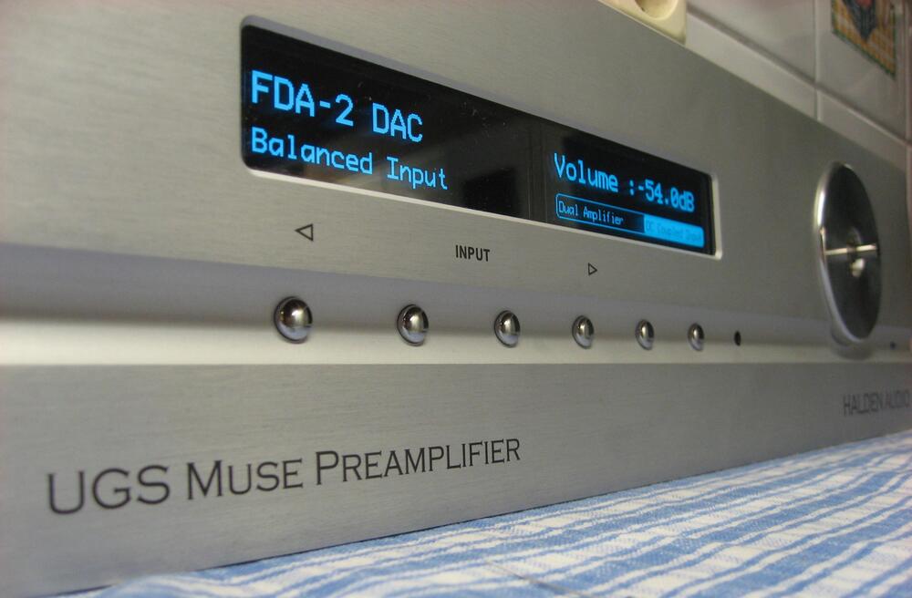
Not to disrupt the construction portion, but just got this up and running over the break, and put it in the system for a listen today. In my typical tradition, currently uncased. This is a UGS Muse preamplifier. This uses the UGS 3 Universal Gain Stage (Pass Labs XP 12 and I believe XP 30 use these), with the Muses 72320 volume control chips. This was developed on a French forum (homecinema-fr.com), originally with a relay-based volume control, and then updated with some redesign for the Muses chips. There are threads on diyaudio for a board group buy there as well. The preamp is fully balanced differential, with 4 inputs and 2 outputs. Even though it provides a HT bypass function, I may hardwire one of the outputs for monitor functionality for headphone amp use. This uses Salas shunts providing the +/-24V for the UGS modules, and regulated down to +/-16V for the Muse chips. Custom Toroidy transformer (4x24V and 2x8V secondaries, dual 115V primaries in their Audio Supreme version). This was mostly surface mount, and was a challenge to build. The 100 pin CPU (STM32 ARM) was a good time to solder, with a size of about a dime. I've only listened to this for about 20 minutes or so today; it sounds very good, but getting the Pass Aleph P out might not be so easy The last picture isn't mine, but shows another builder's case layout. Mine will be somewhat similar I think.
-
Not a construction dude, but the waviness in that wall would drive me nuts. I wasn't sure on your post if you think you can straighten it?
-
Happy belated Birthday Ric! It sounds like you had a great one... well, other than that movie.
-
I'm just driving ortho's (T50RP modified, and now a pair of DCA Ether C Flows). I wouldn't even consider trying to drive speakers with it. Caps in the GRLVs are Panasonic TSHA 4700uf 63V. And Merry Christmas to you!
-
I wouldn't think that large transformers would equal less heat; maybe more since the unloaded voltage will be higher. You can remote mount the pass devices for the GRLVs; I'm doing that on my DynaFET. You are doing dual mono, so you have 2 CFP2 boards per GRLV. The DynaFET is similar, with a pair of DynaFET boards powered by one GRLV. I have that in a 300mm deep Pesante case, with the pair of DynaFETs on one heatsink, and the GRLV on the other. The GRLV heatsink gets almost as warm as the DynaFET side does. In your case, I might consider rotating the GRLVs 90 degrees to point the pass devices at the sides of the case and mount the pass devices there, either directly to the side or on your L bracket? Also, are you sure you have the rectifier boards in right on the GRLVs? I guess one side wouldn't work if it was backwards, and you are using the 3 bridge boards, which I'm not.

-
Happy Birthday Ken! I hope you have a great one!
-
RIP Andre Braugher - actor from Brooklyn Nine Nine https://www.cnn.com/2023/12/12/entertainment/andre-braugher-obit/index.html I think I first noticed him in a miniseries, Thief in the 2000s. Way too young at 61.
-
Curious as to what the cabinet is if you can remember. I could use something like that.
-
-
I was just poking fun. The reason I don't like them is there is too much chance of misconnecting something in the future. Crimped connectors (Molex KK, Spox, etc.) do it once and done. I haven't used the phoenix connectors enough to know whether they loosen up over time or not. I suppose they can/could. I do use them when initially building/troubleshooting if applicable, but replace with something else once done.
-
For the amp portion, I like the layout on the right better, with the tube input boards right along the center. You really are going dual mono, aren't you? For the PSU, that does look tight. I think you might need more heatsinking for the GRLVs, particularly if you are going to be running some speakers judging from the binding posts I see. The GRHV100 is too close to the IEC as it is. How big in VA are the low voltage transformers for the GRLVs? And being team crimped connectors, I'll ignore those phoenix blocks
-
I think it is just a convenience factor, as all headphones aren't wired for balanced (as well as power amps, etc.). Home audio components still live in a mostly SE world.
-
I would think for that application it would be the same as how you would wire an SE headphone jack. L+, R+ and PSU gnd for the - for each channel (L and R). For example, look at how Kerry did it for the SS mini dynalo.