Pars
High Rollers
-
Joined
-
Last visited
Everything posted by Pars
-
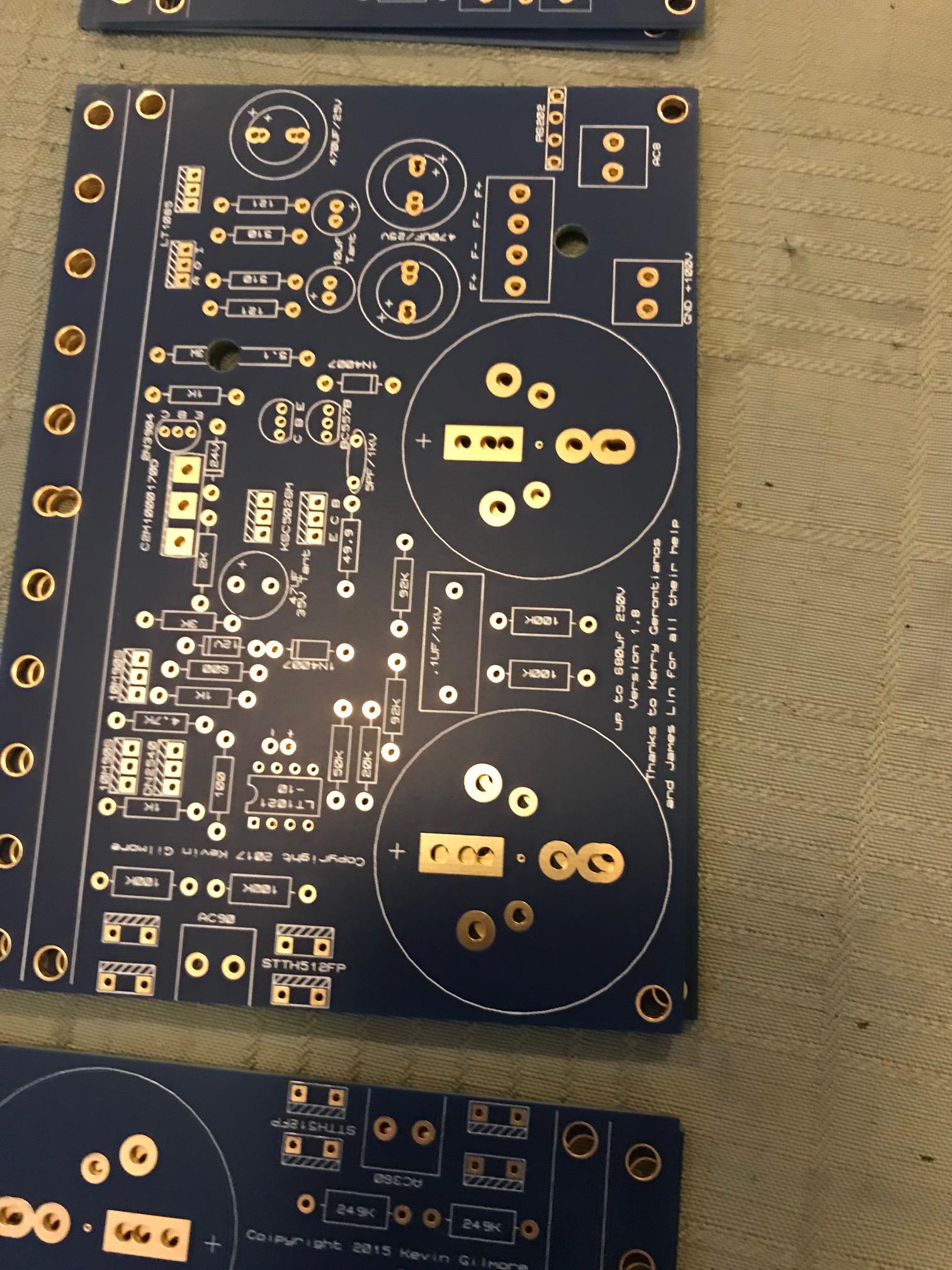
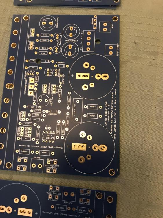
I would think it would be OK to run all of these thru a single umbilical. Most people use Amphenol circular connector, MIL spec. Another connector I would consider would be JAE. The Counterpoint SA5.1 preamp I used to have used these, and they seemed pretty nice. Mouser carries them (not sure where you are located). They have 7 pin and 10 pin. https://www.mouser.com/c/connectors/circular-connectors/standard-circular-connectors/standard-circular-connector/?q=SRCN I would use female on the PSU, male on the amp. You don't want exposed Male pins on a power supply for safety. Also, I might have a couple of GRHV 100 PCBs here, though they aren't mine. I would have to ask the owner if he wanted to sell one of them. This is one of the GRHV (100?) boards that I have:
-
There are posts in this thread that discuss some problems between ZF/SS as well. Like this one: I hate to recommend this, but there might be some posts in the HF thread as well, if you can wade thru the bullshit.
-
Generally, for KGs designs, the PCB values are the ones to follow.
-
The vast majority of boards do not have the board mounting holes connected electrically to anything (though you should always verify this). I usually use aluminum standoffs, either 4-40 3/8" or M3 10mm.
-
Not a good look replying to a 17 year old post for your 2nd post here...
-
-
Most of them don't seem to want to deal with small quantities, and if they do, the price is insane (~$500 for 1 piece, Toroid Inc.). I checked Bridgeport Magnetics, I think they aren't interested in 1-2 pieces. Others won't sell to individuals, only businesses. I'm guessing Plitron is in that boat as well, or would be insanely priced. Antek doesn't do custom, so it looks like I may wind up with 3 Antek transformers for this project. I think that is who Kevin is using as well, but I'll let him pipe up if he wants to.
-
Kevin pm'd me with a don't use warning so posting here, in case others are considering using SumR. I'd forgotten about the megatron rebuild escapade.
-
Transformers (US): Is SumR still a good transformer? Trying to get a quote from him, but Richard seems to get confused easily. I was asking about encapsulation and provided a picture of the 2x30 transformer he did back during the dynaFet GB (2010) just to ask if that is what an encapsulated transformer looks like, and he provided me a spec sheet (for a quote) on that transformer, in addition to the one I was asking for. He still hasn't come back with pricing yet. I realize 1-2 transformers is small potatoes, but still...
-
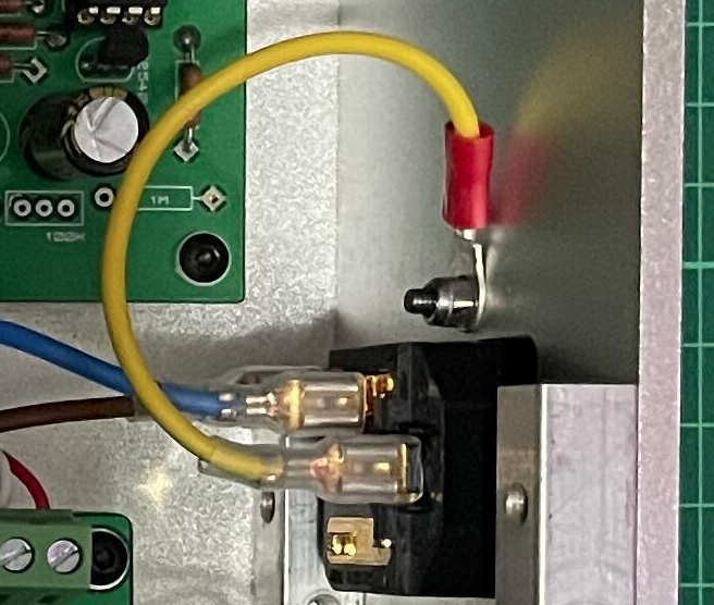
PE = Protective Earth (i.e., the ground on the IEC connector to building ground). That connection appears to be there on the PSU:
-
Great source for Molex connectors, at really good pricing: Sager Electronics (https://www.sager.com) Shipping isn't very economical ($15 on a $35 order), but the pricing if you need much of anything makes up for it. Example: 08-52-0123 Molex KK pins, $0.143 on Mouser at 100 qty, $0.0857 on Sager at 100 qty. Two line items at 24 pieces each were $13.90 on Sager vs. $24 on Mouser. I'll have to check their other lines.
-
Oh god, ASR. I can't stand that site. Known Topping shill as well.
-
I built and have a GRLV that I use for my DynaFET configured for +/-30V and have used it ever since I got the DynaFET running, so probably 4 years or so (would have to look at the thread). I'm pretty sure the tantalums are 35V and never had any problem with them. I'll look later today to confirm. I never tested the MJFs or MJEs (would have to look also to see), but bought them from Mouser as I do almost all of my parts. In process of casing it so it is torn apart right now.
-
Happy Birthday Ryan! I hope you have a great one!
-
Happy Birthday! I know you don't post that here (saw it on FB, and it's my sister's birthday today as well). I hope you have a great one!
-
Yeah, that could work, though I'm not sure why everyone breaks taps? Are you tapping by hand or using a drill? By hand, do a couple of turns, back out 1/2 turn or so, continue, rinse and repeat. I've never broken a tap, even on blind holes with a bottoming tap.
-
Damn, a class act. RIP Mr. Belafonte.
-
From recall, it seemed that the Dynahi was more clinical than the CFA3. Not that the CFA3 lacks detail at all, I guess your description of rude might be a good way of putting it. They are both great amps, I just prefer the CFA.
-
I personally prefer the CFP3 to a Dynahi, but I have only compared SE directly. The CFP3 is probably my favorite dynamic amp, but my SE Dynafet is awfully close (and better than an SE Dynahi in my opinion). I've never built a Beta22, but have heard them at meets (10 or more years ago). I don't recall being particularly impressed then, even though I have a lot of respect for Ti.
-
Hence the !digitalRead call. Clever.
-
-
-
Happy belated Birthday!
-
Happy belated Birthday!
-
Tested the two C2M devices I pulled out of the Carbon board last night on one of those cheap chinese device testers. One of them tested as an NPN, the other as a MOS FET. Another new one tested as a MOS FET as well, so guessing the one that thought it was an NPN was the bad one. Tossed it.