jamesmking
High Rollers
-
Joined
-
Last visited
Everything posted by jamesmking
-
some (usually expensive) scopes have the option of setting their input impedance to 50ohms or 1Mohm. stax headphones are high impedance and draw very little current from the amplifier and so the scope should be set to high impedance. Setting the scope to 50ohm input impedance would draw far too much current and risk damaging the scope. If your scope does not have switchable input impedance then it probably has high impedance inputs by default. Stax amplifiers are can output 100V or more of audio. Most scopes with 1:1 probes will overload and can get damaged with that level of input. X10 probes reduce the voltage by 10 times providing more protection for the scope as well as raising the input impedance from 1Mohm to 10Mohm (usually).
-
-
have you designed the amp side as single ended i.e. rca input or balanced i.e. xlr input? if you are running single ended then the - input side needs connecting to ground. assuming that is ok next check the input (i.e. grids) on the 6922s that connect to the inptut and check you actually have a signal on both. next check the input i.e. grid of the other 6922s to check you have an input to them next check the grids of the el34s to check they have an input this should give you an indication of where your signal is disappearing. I assume you scope is set for 10M input and NOT 50ohm... also I assume you scope probes are set to x10 so you don't overload the front end of your scope I also assume you have checked all the dc voltage inputs to the amp board and they are correct. have you got a volume pot on the input or are you feeding 1Vrms directly into the amp? if i remember correctly the min t2 is about x1000 gain
-
-
normally I would be happy to help, but I am at my parents and don't have access to a mini T2 to measure until I return to my home. im not sure of your level of experience, so my apologies if some of this is obvious 0. be aware working on a powered amp exposes you to the risk of electric shock and you should only be doing this if you know how to be safe and have a good quality multimeter. 1. I would build and check the psu is working without it connected to the amp. I assume you have build golden reference high voltage supplies. Advice on these can be found on the thread for the gr hv. 2. before i would think about powering the amp board I would carefully inspect the solder joints looking for bad joints and solder bridges with a handheld magnifier or better a microscope. 3. I would verify as far as possible the component placement, orientation vales are correct. If you have a set of very fine spring loaded probes like those sold by probe master you can check for continuity/shorts between components referencing the schematic. 4. i would strongly suggest that testing is initially done on using variac and slowly bringing up voltages to their normally working levels, measuring psu rails and looking out for smoke, bad noises etc. 5. i would strongly suggest using cheap valves for initial power ons until you are confident the amp is stable and working correctly. 6. I would monitor the dc offset (dc voltage between + audio output and ground) and dc balance (dc voltage between - audio output and + audio output) 7. I would not think about connecting expensive headphones until I have put in some audio test signals and looked at the output on a oscilloscope and had the amp running for at least a few hours. 8. if you have a temperature probe, its also worth measuring the transistor case temperatures and the temps of any high wattage resistors.. if you still need specific voltages I should be able to help after jan 9th good luck
-
pray to the deity of semiconductor manufacturing (in a reverential voice tinged with grief).... 🙏 oh Nosemi please hear our plea for our DIY hobby.... in the name of silicon please bless us with some manufacturing and fill up our inventories In the name of NPN and PNP blessed are the mosfets, depletion or enhancement for the DIYers shall inherit 10M90S and it was good Let not the ebay scammers rebrand and re-etch for they will be accountable to silicon and burn in the foundries of ixys for all eternity Let it be known Toshiba and NEC will escape Renesas Sanyo and Fairchild will rise again and return to us all for now and for evermore Ahmen. (The DIY hymn book chapter 11 covid 19 to recession 2008 verses 1-4)
-
about the only hope is from a forum member or take chances with fakes on ebay 😞
-
wow AI is even more useful than I thought..
-
on windows chrome saves with correct extension....
-
Im using windows and chrome. I right click on the download, select open in new window and then hit enter in the url of that new window to download....
-
the speaker mixes through headphones sounds absolutely terrible, artificial and very very strange sounding bass, absolutely horrible, imaging is all over the place sounds like someone has strapped the worlds worst setup sub woofer behind you. Headphones mix sounds ok. But there is nothing pure acoustic and simple, like solo piano or voice to listen to... just sounds too showy. The Strauss trebble end is slightly bright and hard, bottom end of the bass is rather boomy and feels compressed in the middle, completely lacks micro dynamics... sounds like its mastered to be played really loud, apart from the lack of tape hiss I don't find it in any way batter to sympathetically transferred 1960s analogue recordings. Aayushi Karnik - Solid Ground (headphone mix) the voice is just lost in the mix sounds like the singer is behind a curtain far far behind the main instruments. Mark Sherman & Joe Magnarelli - Suddenly (headphone mix) piano sounds strange, again bass boom and sounds electronically processed.. Paloma - Ode to Joy (headphone mix) her voice sounds like she's shouting down your ear the peaks in her voice are mildly painful. EX38 - Ring No. 5 (headphone mix) WTF I cant tell how much is the electronically generated instruments and how much of it is the effect of the recording. Feels like im trapped inside sampled midi instrument hell. none of the tracks have a sense of natural acoustic, are dry or artificially dried but then warmed up with excessive bass and reverb to simulate an acoustic. I think this is just another example of electronic fuckery like the short lived DG 3D sound processing on a few classical cds... its not about natural sound its about lots of sounds....
-
mouser currently has ksa1156. radio spares has STN9360, FJPF2145TU and FQPF8N80C
-
Stax headphones are designed to take hundreds of volts of audio signal , a small offset of a few volts are absolutely not an issue. The offset will change with temperature. ALL amplification devices are somewhat temperature sensitive - including valves and transistors. you can demonstrate this easily, just blow gently onto the valves and what the offset change... This is why you are getting different results with the cover on and off. So don't worry you are not going to hear any difference or cause any damage to the headphones or shorten their life...
-
yes, for short term testing, e.g. for checking output voltages, voltage regulation etc. (P.S. its also possible to test the grlv with no heatsink with no load.)
-
I hate nosemi...
-
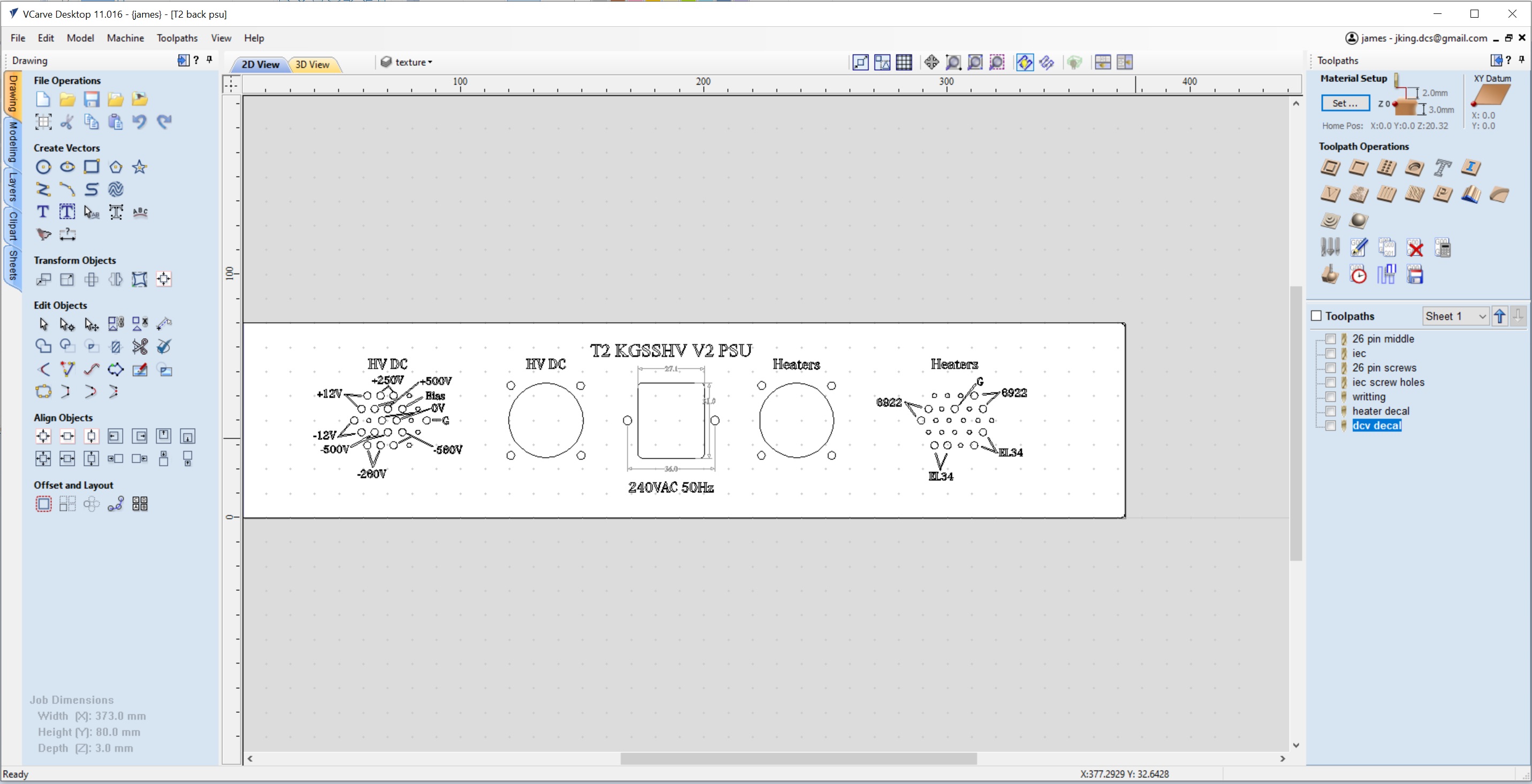
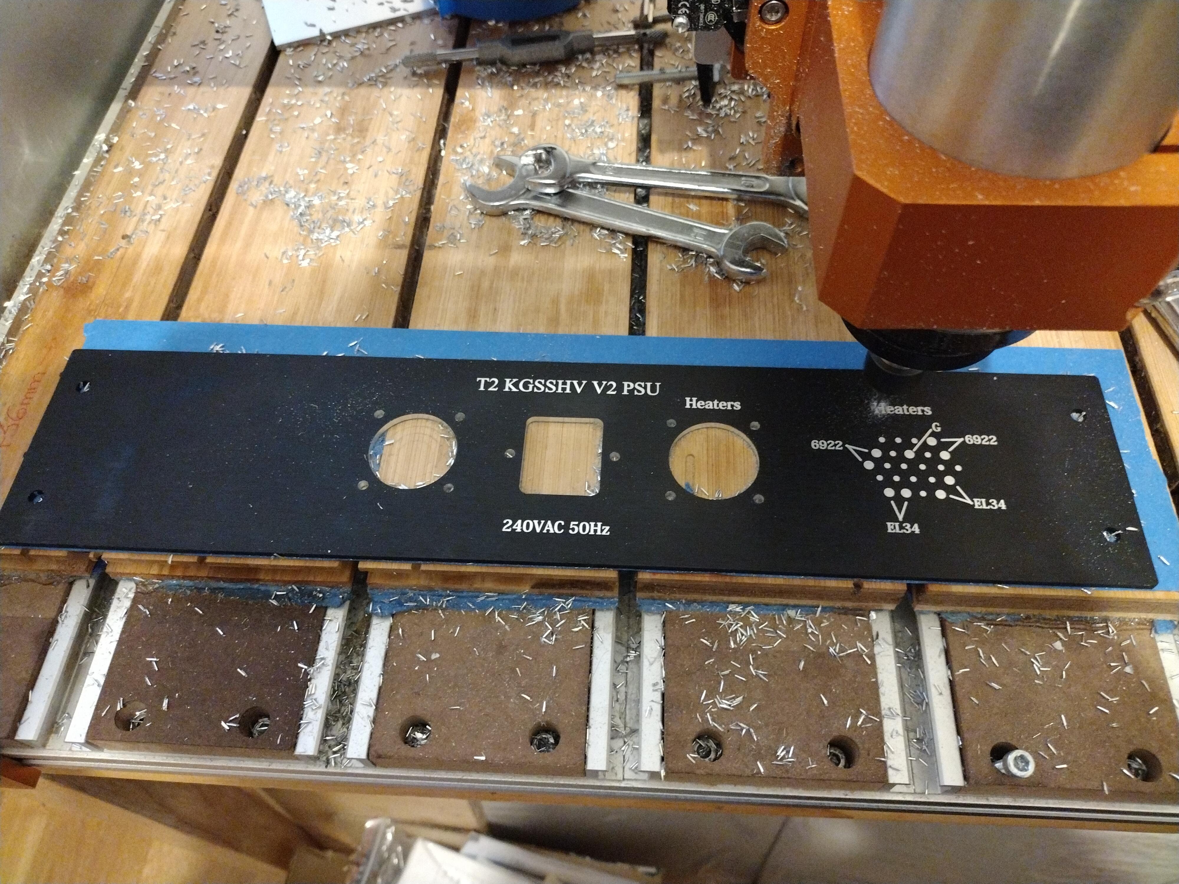
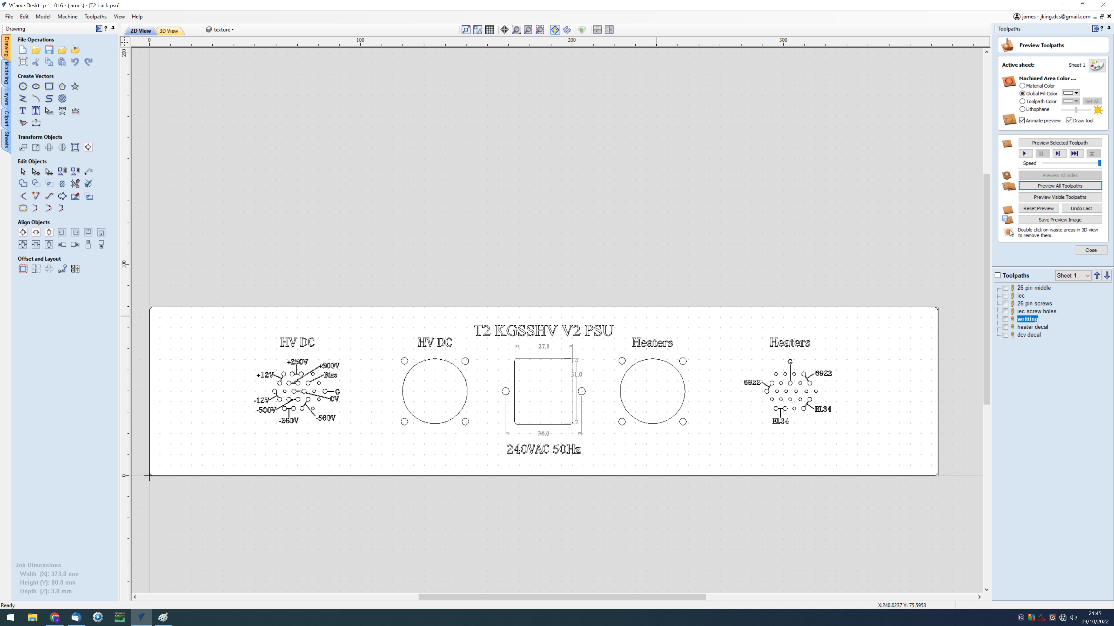
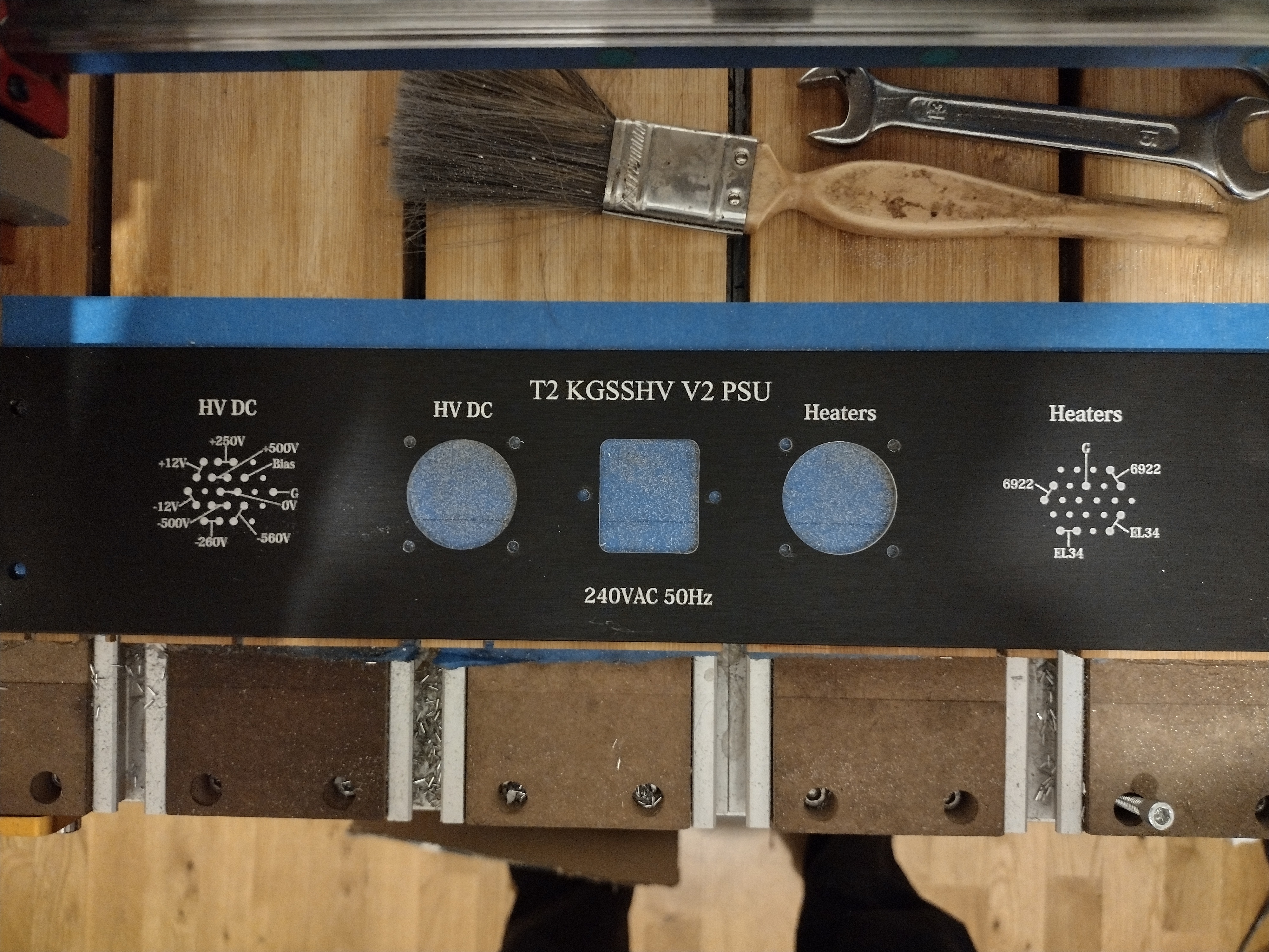
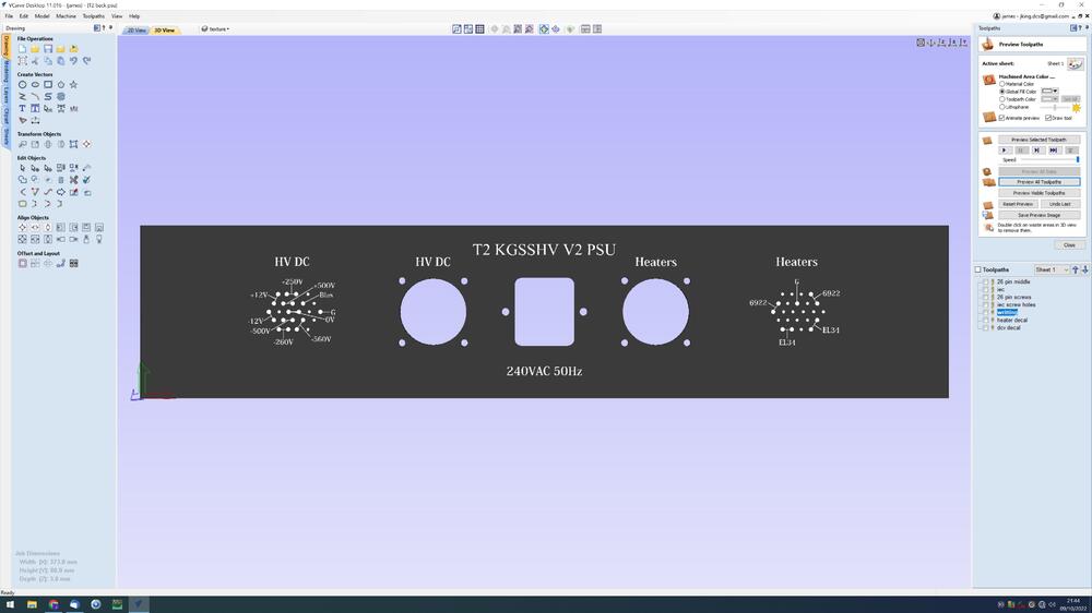
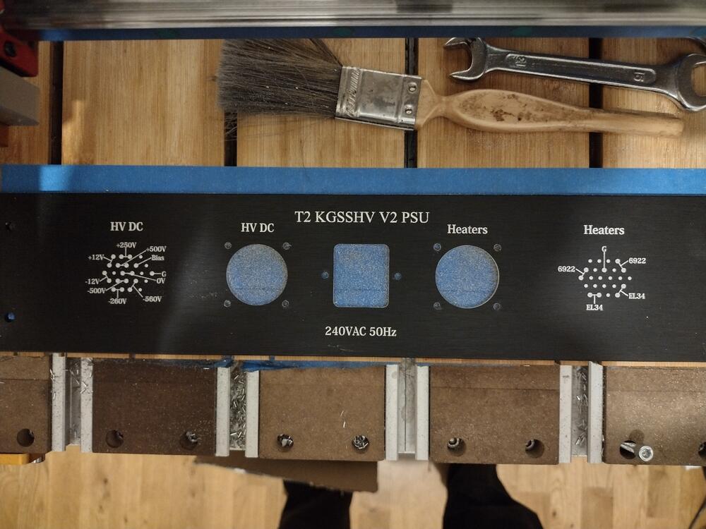
T2 psu back panel, design and cut. I wanted to have the pin outs of the sockets for the umbilical chords from the psu to amp to be on the psu back for future reference.. I decided to go for 10degree 0.1mm tip engraving bit for the lettering, 0.025mm depth of cut rather than laser. Screw holes done with 3.175 end mill and main cut outs 6mm end mill. Now I have a good collection of quality bits and little experience now. CNC machining is starting to become FUN 🙂. Its so much nicer and more satisfying watching a CNC cut than using a hand drill and Dremel... Tool changing is a bit of a hassle and then I have to use a Z block and Z probe command get the new Z height reference for the tool sickout. So I try to minimise the number of different tools used. Tape hold-down and CA glue works perfectly. I'm very happy with the surface finish, perhaps the text for the pinouts and lines could be a little narrower, but its certainly not a disaster. Cut still currently in progress: The nice thing about symmetrical panels is that you can always adjust your settings and have another go with the other side... I decided to decrease the line width by half, nock 20% off the size of the socket decals, decrease the socket decal font size, change the style of the lines and reduce the engraving depth from 0.025 to 0.02mm... I think the new version should look a little less blocky and a bit more refined... The 0.02mm engraving depth is slightly too little, other than that I think its an improvement.


-
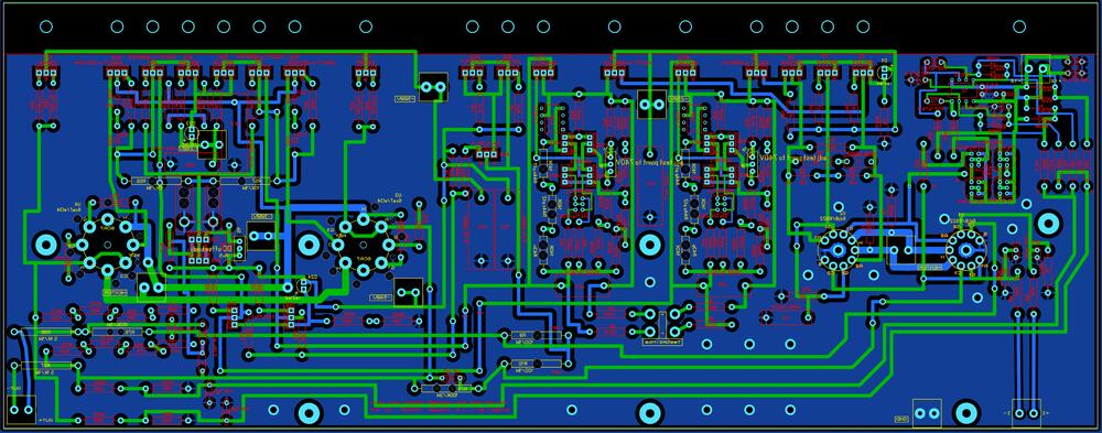
I completely agree that if you have T2 pcbs already its not worth getting new ones. I'm thinking gerbers with minimal changes for new builders who want a build and forget solution only using available transistors. Serial/habitual/continual modifiers can always edit the gerbers of my or others T2 pcbs.
-
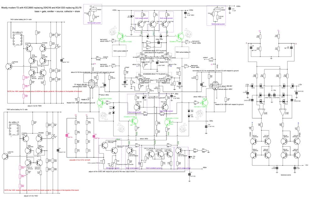
*Sigh* why can't we have nice transistors?... I have updated the schematic to show both KSA/KSC and TTA/TTC series transistors. I'm working on changing the gerbers so that leg twists will not be needed 🙂 One channel done, I think, needs checking...
-
So if my brain is not totally scrambled (which is possible its my first week back lecturing). KSC2690 or TTC004 NPN replaces 2SK216 N channel. Base-> Gate, Emitter -> Source, Collector -> Drain and Ksa1220 or TTA004 PNP replaces 2SJ79 P channel, Base-> Gate, Emitter -> Source, Collector -> Drain which gives modern T2 circuit (green replacements original moved to the side)
-
This depends on what DC output voltage you are building for which depends on the input AC voltage to the GRHV which depends on the AC rms output of the transformer you are using... for example if you are building for 400V DC output to power for example a blue hawaii then you need about 360VAC rms input to the golden reference. (360VAC rms is about 509 peak when full wave rectified by the diode bridge before the input cap (DC voltage * square root of 2) which is enough for the internal voltage drops inside the GRHV and gives you some margin so the GRHV can actually regulate). Mains voltage typically varies by about +-10% so that is factored in to. But if you mains voltage is high then the input filter cap will see additional voltage so 550 rated cap should be fine for 400VDC output... If you are going for 450VDC output (about the maximum a GRHV can do) then your cap is going to be marginal and a 600V rated cap would be better.... The output cap should only see the output DC voltage, so if your GRHV is outputting 400V DC a 450VDC or 500VDC rated output cap should be fine. Dont forget many high voltage caps especially the 680uF are 80mm tall and so too tall to fit into a 2U case.... Kemet make some nice high voltage caps with life time ratings of around 15000 hours. https://www.mouser.co.uk/c/passive-components/capacitors/aluminum-electrolytic-capacitors/?q=kemet 550V&life=10000 Hour~~20000 Hour&voltage rating dc=550 VDC&rp=passive-components%2Fcapacitors%2Faluminum-electrolytic-capacitors|~Life
-
CRCW2512475KFKEG which is same series as the original and so is 500V 1W and 475K should be fine in this application and is in stock at mouser.... lets say the resistor has the full 500V across it - which is worst possible case, V/R = I so the current through the bleed resistor would be 500/475000 = 0.00105A power dissipation in the bleed resistor would be W = I * V = 0.00105 * 500 = 0.53W and so well within the 1W capacity of the resistor... if the resistor has less than the full 500V across it the power dissipation will be less...
-
Thanks for the photos R30 and R31 are in series and look to be the bleed resistors for the high voltage input smoothing cap so the voltage is shared between R30 and R31 but the input cap has the highest voltage across it. 200V working voltage is probably not enough here since the input is probably rectified to more than 400VDC R28 is the single bleed resistor for the output cap and so has the entire output dc voltage across it. So unless your psu is only outputting 200V or less, then a 200V working voltage resistor will definitely not be enough by a large margin. Since its a bleed resistor the exact value is not critical, a higher value would simply mean the high voltage would bleed to 0V at a bit slower speed and a bit lower value would very slightly increase power consumption when the power supply is on...
-
I don't have a layout or schematic for the golden reference HV SMD but if it is similar to the through hole. The only places resistors with 250K+ resistance are used is in 1. bleed resistors for the high voltage smoothing caps - and so subject to high dc voltage. My best guess would be they are using a single resistor for the bleed unlike the through hole which uses two 250K 1/2W. So a single 1W 500V 510K would be about right here 2. output sense resistors - and so subject to high dc voltage 3. in the 580V bias circuit and so again subject to high dc voltage But this is only a guess based on looking at the through hole schematic... I have never built a golden reference hv SMD version.
-
mostly modern T2 or possibly fully modern if the tta/ttc substitution for the 79 and 216 proves to be reliable. I don't think I will ever build an original.
-
REQUIRED blue led is the blue ring around the power button on the power supply....