jamesmking
High Rollers
-
Joined
-
Last visited
Everything posted by jamesmking
-
Well spotted! I didn't notice they are not using the 10Hz standard. I wonder why are they using 100Hz?
-
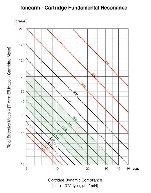
well specifically, The Denon cart user manual talks about the included headshell will provide the appropriate overhang - well thats BS because there is no standard. They may be referring to SME arms with bayonet fitting. The vinyl engine has specs for the technics arm geometry and its NOT the same as the sme bayonet geometry on say a SME 3009. The effective length, offset angle and overhang are all different, and in fact the sl1700 mk2 has a different offset angle from the mk 1 and therefore different zero tracking error points on the record. The cartridge could be used with the existing technics headshell. The user manual only specifies the weight of the cart and headshell which is not helpful in working out the resonance frequency if the technics headshell is used. The frequency response spec in the user manual does not include + or - dBs and so is meaningless and there are no specs on tracking ability either. There is some information about the diamond BUT nothing on the effective moving mass. the spec sheet contains even fewer specs than the user manual (omitting any information about the diamond)... Finally buried in the Denon blurb in spec sheet is says the headshell is 6g so the cart is 12.5g the suspension is 5*10*-3m/N which is very stiff, but then the cart is quite heavy. The technics service manual says the arm is effective mass 22g so with the technics shell you are looking at a resonance of about 10Hz ish which is ok. According to the technics manual, the arm can ballance carts up to 11g with the technics headshell and the denon is 12.5 so you will need to use a lighter headshell or add extra weight to the back of the arm.
-
oops In my day job I usually lecture to 18+ audience and if no one gives me a limitation on detail I tend to go for high levels of detail because in reality its almost never as simple as X is better than Y, it's almost always the case X and Y offer different compromises and its (in my opinion) important to understand what is going on and understand the compromises.
-
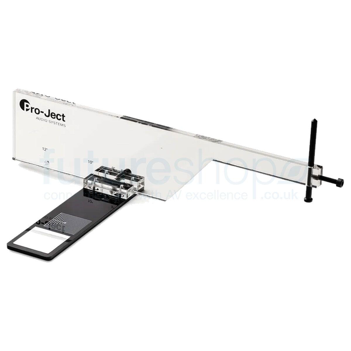
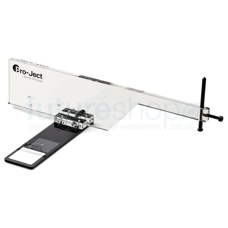
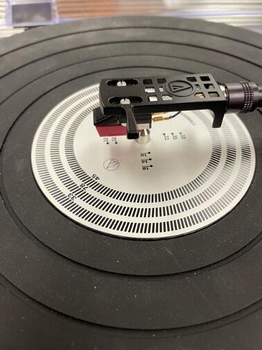
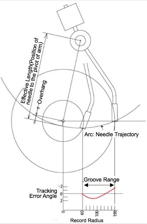
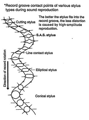
Ok i will open the can of worms. Please note I have had to make a LOT of generalisations here: records are cut with a linear tracking arm and ideally should be played back the same way so the play back diamond is aligned with the cutting diamond. In reality quality linear tracking arms are not easy to engineer and tend to be expensive and so arms that track in an semi-circular arc often used because they can be easier and cheaper to make. But this introduces errors between the alignment of the cutting diamond and the semi circular arc of the playback. you would expect the semi corcular playback arc to only align with the cutting arm at one point. But by some clever geometry it is possible to align two points and reduce the tracking error. If the two zero error points are too close together you get more distortion at the beginning and end of a record then optimal and less distortion in the middle of the record. If the two zero points are too far apart you get lower distortion and the beginning and end but more distortion in the middle. Given different records have different amounts of the record with music on there has always been arguments about the exact placement of the two zero tracking points. Unfortunately to do this trick it requires the cartridge to be skewed compared to the pivot in the arm AND requires the cartridge to overhang the centre point of the record by an amount. This is made more complicated because not all arms have the same pivot to cartridge mounting hole distance and not all cartridges have the same distance from diamond to the mounting holes either. The result is that the diamond to arm pivot distance is not standardised at all. As a result the cartridge has to be moved forward or back in the headshell and/or the base of the arm moved to get the correct overhand from the diamond to the centre of the record. There are various ways of attempting to make this alignment, Some rely on the cartridge being exactly parallel to the headshell and assume the headshell is correctly angled and then slide the arm base or cartridge back and forth until the diamond overgangs the centre spindle by the correct ammount Others methods assume the overhang is correct and have parallel lines at the two zero tracking error points and ask you to adjust the angle of the cartridge in the headshell to be parallel to the lines. A few advanced (and generally expensive) alignment tools actually allow both overhang and angle to be set. However, all this assumes that the diamond is at 90 degrees to the cantilever and the cantilever is parallel to the cartridge etc. In theory proper alignment would be done looking at the diamond rather than the cartridge body. another issue is that the suspension on the cartridge acts like a spring and will resonate at a certain frequency, the higher the mass of the arm + cartridge the lower the resonance frequency. The more stiff the suspension the higher the resonance frequency. If the resonance frequency is too low i.e. the mass of the arm and cart too high and the suspension of the cart too soft then the resonance can be excited by record warps and the suspension can resonate like crazy and even bounce the stylus out of the grove! If the suspension of the cart is too stiff and the mass of the arm and cart to low the resonance frequency can be so high low frequencies in the groves can excite the resonance and cause the suspension to go crazy. This is another reason low mass carts usually have soft suspension and high mass carts usually have stiff suspension. This means some arm and cartridge weight combinations simply will not work well. There are online calculators where you can enter the moving mass of the arm, the mass of the cart and its suspension stiffness and get out the resonance frequency. Similarly some cartridge mounting hole to diamond lengths are outside the adjustment range of some arms or headshells and so it's impossible to get them reasonably aligned - when you decide what reasonably aligned is. Similarly some carts are too light or too heavy for the arm to balance correctly and you either have to add weights to the headshell in the case of too light weight which has the side effect of changing the moving mass and therefore the resonance frequency or add mass to the back of the arm if the cart is too heavy (which will also change the resonance frequency) In other words there are a whole set of interrelated compromises and assumptions about cart mass and suspension stiffness and diamond to mounting hole distance. MC vs MM moving coils generally have a much lower output voltage than moving magnet but a much lower output impedance. A quality step up transformer designed for the job into a mm preamp input is certainly an option. In my experience step up transformers are sensitive to external magnetic fields so try to keep it away from power supply transformers, mains wiring etc. Your Denon MC has 0.25mV and MM carts somewhere around 2mV. So about a x10 step-up or 20dB gain. Generally dedicated Mc preamps will boost to line level ~1.5V or around x1000 or 80dB gain and do the RIAA equalisation and feed into a line level input on the preamp. Low noise MC preamps are a bit of a challenge given the gain they have to do. In general dedicated MC preamps have multiple resistance loading options, many have multiple gain options and some even have capacitance options to. i.e. more scope for tweaking the sound. Is it worth going MC? much more difficult question to answer In general MC are better sounding than MM for a variety of reasons. MM are usually the lower cost option and more design and precision goes into the MC carts which are perceived as the premium cost option. In general MC have lower moving mass because the diamond is attached to a cantilever which is attached to some lightweight coils and the magnets can be relatively large and fixed to the cart body. MM can have lots of coils fixed to the cart body but the magnet is attached to the cantilever and is generally quite high mass. Its that mass the diamond is trying to move when it reads the record grove. MCs generally have better profiled diamonds too which can read more of the fine wiggles in the grove than a cheap profile like a spherical diamond. better diamond profiles will also reduce record wear because the tracking weight is distributed over a taller slice of the grove. MM carts are usually lower mass and so can have a more compliant and soft suspension which in general helps with low frequency tracking performance, but generally have less refined diamond profiles resulting in poorer high frequency tracking but as a result are cheaper to manufacture. MCs usually have better diamond profiles and this helps with high frequency tracking performance but are heavier and so have less compliant suspension and poorer low frequency tracking and since making diamond profiles is precision engineering this makes MC carts more expensive. Because of the higher stiffness/lower compliance of the suspension of the MC cartridge they generally require higher tracking weights to keep them in the grove, conversely MM carts usually require less weight. MM around 1.5Grams MC around 2.5grams. Too little tracking weight and the diamond stops following the grove properly and as well as creating more distortion this can damage the record. So there is a tradeoff too high tracking force and you add to diamond wear and record wear, too little tracking force and your diamond starts to cut its own path through the record groove. Against all of this you have to bear in mind if you wear out the diamond or damage the cantilever, many MM carts have user replicable diamond and cantilever and the diamond profiles are usually cheaper so the running costs are lower and you can keep a spare stylus around for a quick swap out if needed. Some MMs even have a range of available diamond profiles so you can upgrade the performance by replacing the diamond/ cantilever with a higher end one e.g. ortofon om series MM carts. Very few MC carts have user replaceable diamond/cantilevers and so almost all require a rebuild if damaged or the diamond is worn - so the running costs of MC carts are generally higher, in many cases a single rebuild of a MC can be a significant percentage of the cost of simply buying the cartridge again. ( I hope this is not too rambly for you) 😁 please note I have had to make a LOT of generalisations here. There are some high end expensive MM carts with nice diamond profiles and some low end MCs with plastic bodies, low weight and with crappy diamonds (e.g. ortofon mc10 super). Some MC carts can have a high output voltage and some MMs can have a low output voltage (e.g. some grado MMs). etc etc.

-
bit of both. working distance is ok for either a hot air handle or a soldering iron. It takes some getting used to since you have a fixed defined viewing circle, you can't move your head and have to organise everything around that. I personally found that exact head positioning was very critical to get a good 3d perspective view and this meant I wanted to minimise the number of times I looked up away from the microscope.
-
I purchased a cheap rebranded scope from amazon one a few years back for smd and pcb inspection It looks identical to this one: https://amscope.com/collections/student-microscopes-low-power-stereo/products/se420xyz-2l it works. My only complaints are 1. it does not have a zoom 2. its not trinocular so you can't add a camera look through it at the same time 3. there is no real X and Y adjustment. instead it pivots around which makes moving around a pcb a bit of a pain. 4. because the objective lenses are housed in a rectangular box you cant fit a ring light easily. 5. the objective lenses are not a "standard" mount and that limits you options for different lenses
-
The calculation are based on some assumptions and tradeoffs. Ideally you need to know some things about the high voltage power supply the secondaries will be powering. 1. you need to know the minimum voltage input to the power supply to get the required regulated output at the required current. (the minimum input will usually increase with higher current draw). typically this will be a fairly small additional voltage above the output voltage for low voltage power supplies e.g. a few extra volts for the golden reference low voltage and typically in the few 10s of volts extra for the golden reference high voltage power supply. Since this is the absolute minimum you probably want a little more input voltage than that to be safe. 2. the voltage out of the wall also varies. In many countries during peak demand the power companies can reduce the voltage - typically by up to about 5 to 10% so you need about 10% more voltage on the output side than you might think to compensate the electrical grid giving you less than you expect. So we multiply the total secondary output voltage by 1.1 i.e. add 10% 3. Competent transformer design is also assumed. The more current you draw from a transformer the more inefficient it becomes. Which is why you specify the output voltage of the secondaries at the current draw you expect. If the manufacturers are crap and only design the transformer secondary output based on no load being applied you can have issues where the psu loads the secondaries and the output of the secondaries drops so much you don't get enough voltage for the psu to maintain regulation. Conversely if the manufacturers design the transformer properly, specifying a transformer with a much higher secondary current draw than it will actually experience will result in the secondary voltage being higher than expected. Any voltage going into the psu above the minimum amount required to regulate will be converted into additional heat. Any voltage below the minimum to regulate will result in loss of regulation and the output voltage dropping with greatly increased levels of ripple and noise. you also need to make sure the input capacitors in the power supply can handle the peak voltage going into them or their life expectancy will be reduced and in more extreme overload conditions they can fail completely. (the output caps are mostly isolated from the varying input voltage and should only see the DC voltage output the power supply is setup to output assuming there is no failure in the psu which causes the regulation to be bypassed/short out and pass all the available voltage to the output e.g. the pass transistor to be fully switched on or become shorted) [Since minimum dc voltage input for regulation - DC output voltage] is the additional voltage needed to regulate at the required current draw. secondary VAC = (minimum dc voltage input for regulation *1.1 )*0.707 Or secondary VAC = ((DC output voltage + minimum additional voltage for regulation)*1.1 )*0.707 so if we assume 10V more input is needed to regulate than output for 400V output we get: secondary VAC = ((400+10)*1.1)*0.707 = 319VAC
-
Here are a few suggestions. My apologies if you have tried any of these already. If the hum is changing after a few minutes then this implies to me that thermal expansion could be the cause. Are you sure all the pins of any socketed components are gripped well by their sockets? I believe there have been cases where over time some of the teflon tube sockets pins have started to lose their grip.. I would also very careful with the amp off and all capacitors in the psu drained and using a high resolution multimeter check the resistance between the psu connectors and the amp boards to make sure there is not a poor wiring connection due to oxidized wires etc this test will also check for any potential problems with an umbilical if you have the psu in a seperate box from the amp with seperate wires for the left and right channel. I think at this stage you need to start being very systematic and seeing what is going on.. so do you have access to an oscilloscope? I don't have a KGST but I assume it has separate and identical + and - amplification stages for each channel with a phase splitter at the input stage to allow single ended or balanced input... With a scope you can CAREFULLY (10x probe and dont connect the probe ground lead to anything that is live) probe the output pins at the stax socket one by one AVOIDING the bias pin and see if you have hum on both the + and the - outputs of a channel or if it is only the - or + half. This could potentially eliminate half the components of a channel from being faulty. If both - and + of a channel has hum then suspect something common to both which is usually the psu or input phase splitter. If you have seperate psus for each channel then you need to look at the psu rails to see if there is excessive ripple on one of the psus. If each channel shares the psu and only one channel has an issue then its very unlikely to be the psu but it could be the wiring from the psu to the effected channel. If all else fails a scope is an essential debugging tool and you are going to have to compare the good and bad channels and see what is different. good luck regards James
-
Thats whats needed but, stax logic is simple: why make a better product when you can sell something worse for much more and the hifi magazine reviewers are guaranteed to say its the best thing since non-sliced, small batch, organic artisan, seeded, whole meal, bread... *sigh* between on semi and Stax we just can't have nice things.
-
true, which is why I have been upgrading the axis bearings etc. I agree prevention is better than detection, which is why I am going for steppers with double torque than the originals, plus the software that comes with the closed loop system provides graphs, including positional error which will allow me to fine tune the pid parameters and see what is actually going on and give me more options to fine tune and correct. I am also learning a lot - which is fun too. I loved metalwork and woodwork at school but when the route of computer science, but have always enjoyed making things - even if it's just putting together flat pack furniture for friends or soldering pcbs.
-
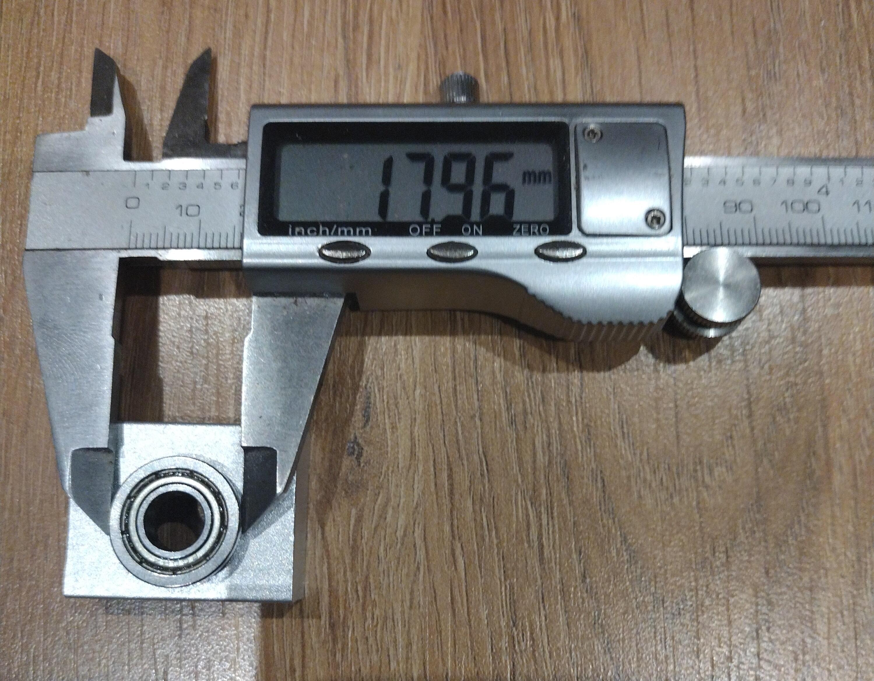
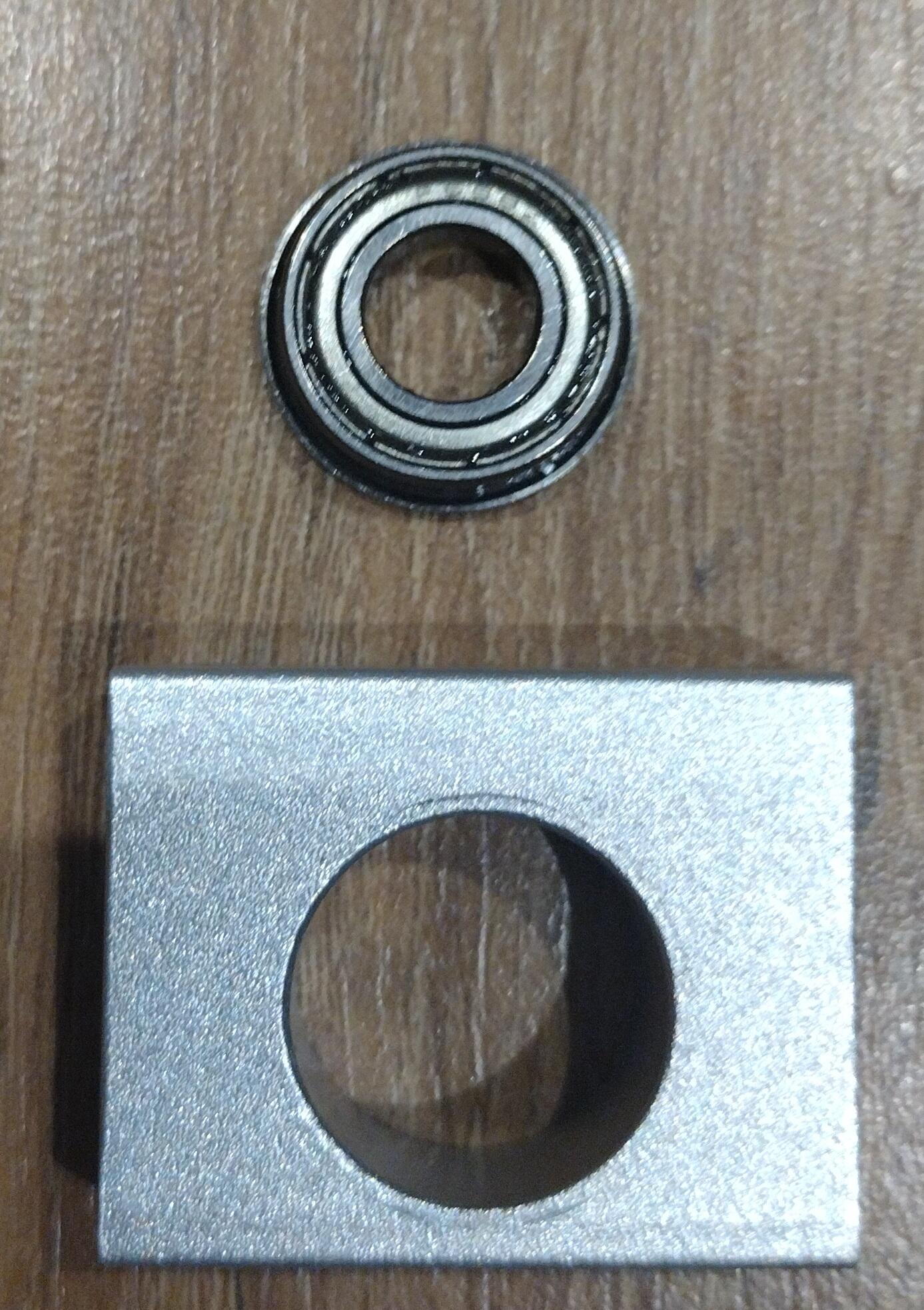
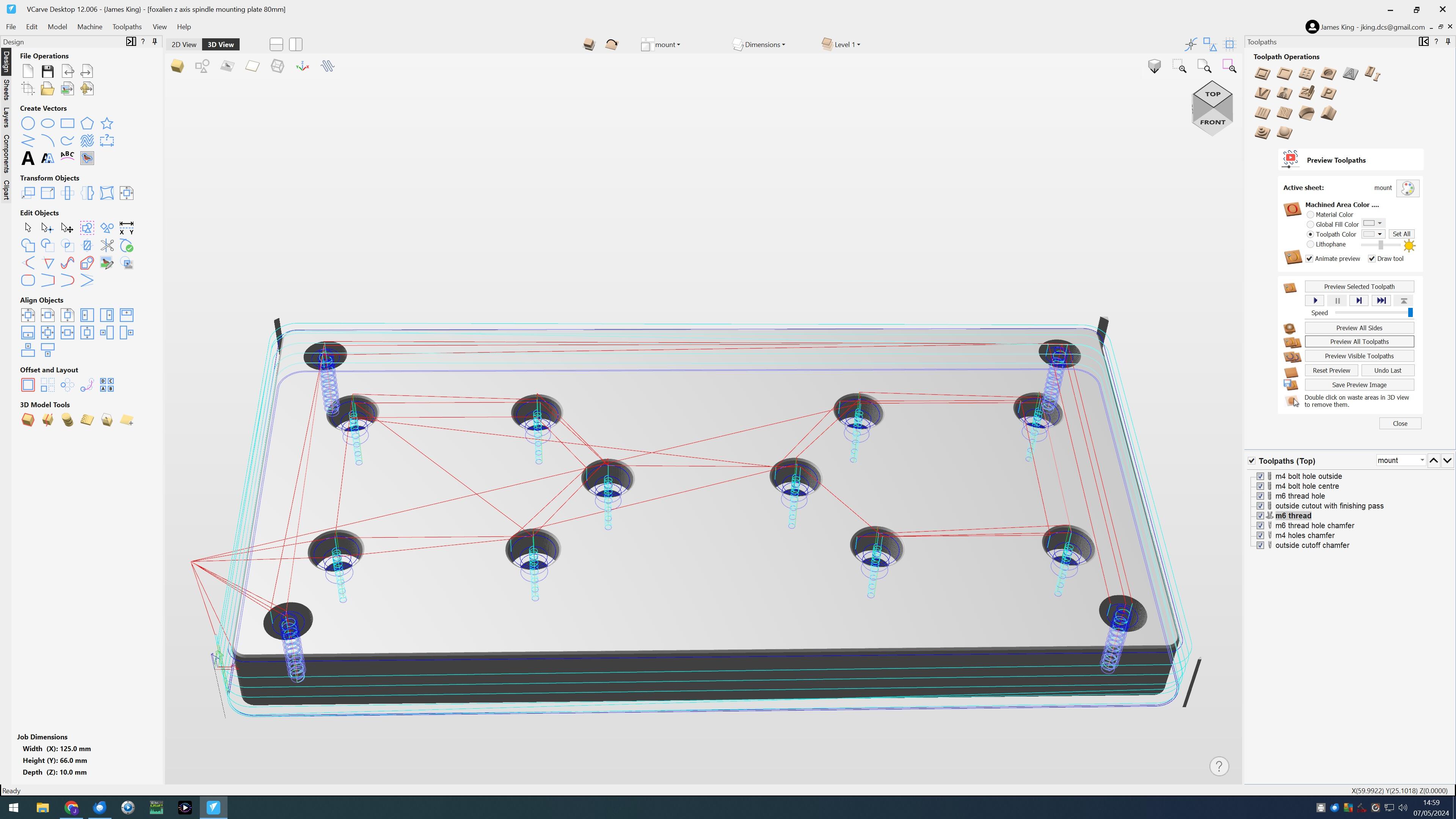
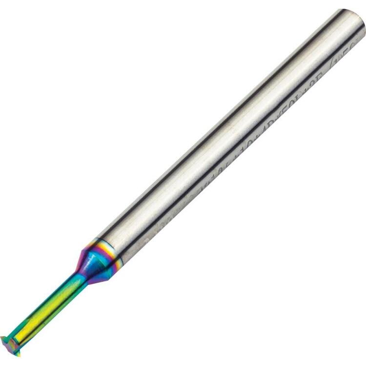
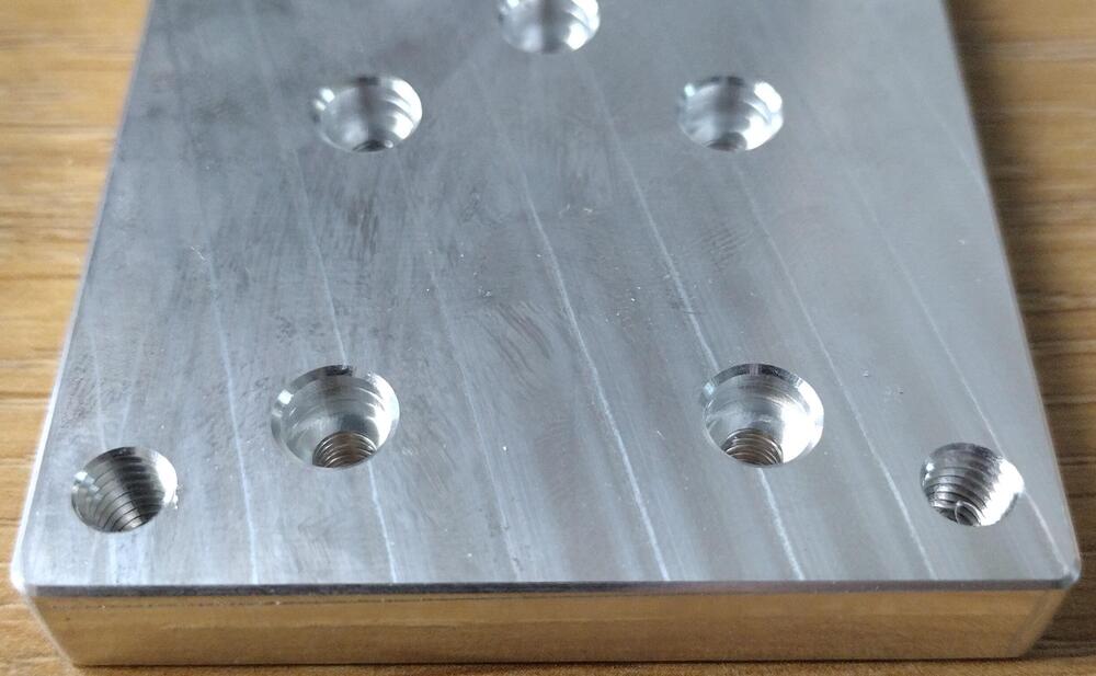
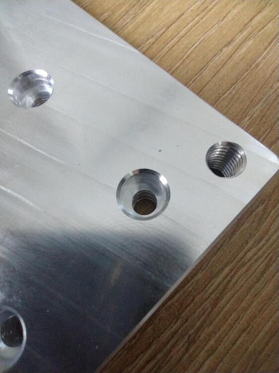
junk z axis. holy crap, I just disassembled the Z axis. The entire spindle weight is held by a 12mm ball screw. On each end of the ball screw is just one f688z bearing - (8mm ID, 17mm OD with a flange 18mm diameter). These tiny bearings have no preload and not designed for axial loads and have axial play. Looks like fox alien are relying on the weight of the spindle alone to push down on the lower bearing and that's the only thing stopping the spindle from dropping. Piece of absolute SHIT! The bearing housing has no recesses, no preload mechanism, no adjustment mechanism, nothing it's just unbelievable. Looks like I'm going to need an entire new Z axis too... Does anyone know if there is a angular contact version of the f688z?? sigh single tooth carbide partial profile (so it will do multiple thread pitches and the tool pressure is a lot less than other threading tools.). It's more versatile and cost effective than buying complete profile thread end mills. With 5 thread mills I have every metric pitch (both fine and course) covered from m3 all the way to m10. https://www.shop-apt.co.uk/single-tooth-thread-mills-dlc-for-aluminium-internal-60/internal-single-tooth-carbide-thread-mill-partial-profile-05-10mm-pitch-dlc-coated-for-aluminium-39mm-head-diameter.html The thread mills don't come with all the necessary parameters (e.g. tooth height, distance from the centre of the tooth to the bottom of the end mill etc.) for the software I use so I had to take multiple measurements with a 0.001mm micrometer and average the results and guestimate other parameters. The threads are m6 I ran 7000rpm, 150mm/min feed, 70mm/min plunge 0.0054mm per tooth chip load, bottom to top cutting a right handed thread. This resulted in the threads being cut in two passes and the chips falling into the bottom of the hole (which I made 1.5mm deeper than needed to hold the chips). To make the thread go all the way through the 10mm mounting plate I found I had to start about 1mm below the bottom of the material, so I painters tapped and superglued a 3mm sacrificial aluminium plate underneath.


-
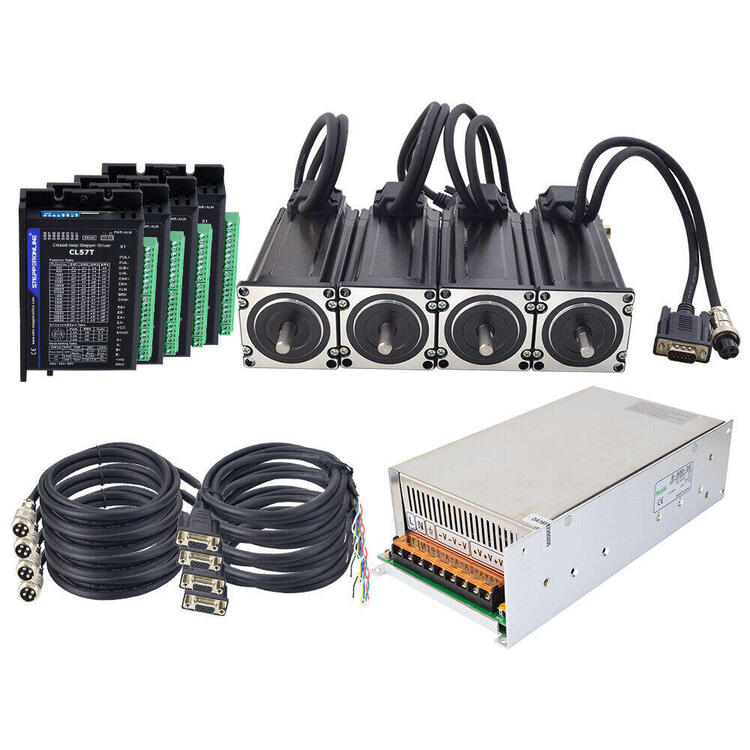
Well, I decided I needed to upgrade my CNC machine (replace almost everything from the original machine I purchased). having already upgraded the controller, spoil board, spoil board mounting and spindle it's time to look at the axes .... First I got myself an 80mm diameter er20 ceramic bearing 2.2KW water cooled spindle with labyrinth seals to replace the cheap 65mm 1.5Kw er 11. To fit the 80mm spindle I had to make a new mounting plate. This included experimenting chamfering and threading. I settled on 0.3mm chamfers at 45 degrees and experimented with thread milling. The result I think is ok: (full discloser I purchased tooling plate so the top and bottom surfaces were already machined flat, but all the other surfaces got machined. I have ordered 4 nema 23 closed loop steppers (3NM - about twice the holding torque of the original open loop steppers the machine came with), which will entail replacing most of the wiring loom, removing the existing open loop motor drivers, removing the motors, some software config of the new closed loop drivers and some changes to the controller wiring. The original divers have no error output pin so the controller has no idea if a stepper has an issue. The new drivers include error output pins so they will need to be connected to the controller. (stock jpeg from the ebay listing, I'm still waiting for delivery) I have also replaced the standard 'deep' groove (6001 series) bearings inside the bk12 bearing housings with angular contact bearings (7001 series) as per this you tube video: I also noticed that all the bearing blocks were attached to the machine with m5 bolts despite the blocks being designed for m6, So I plan to replace those bolts and find a way to make new threads in the machine housings. The nema 23 motors are also designed for m5 bolts but the machine uses m4 (on avery axis except Z), again I don't know why fox alien decided to use one size smaller bolts on everything that drives the axes so I will have to machine new back end plates/motor mounts too. After these upgrades and fixes the only original parts of the machine left will be the frame, axe and the metal case the electronics came in. It's so nice to have a cnc machine so I can make parts to upgrade my cnc machine...

-
portable if you are godzilla or king kong....
-
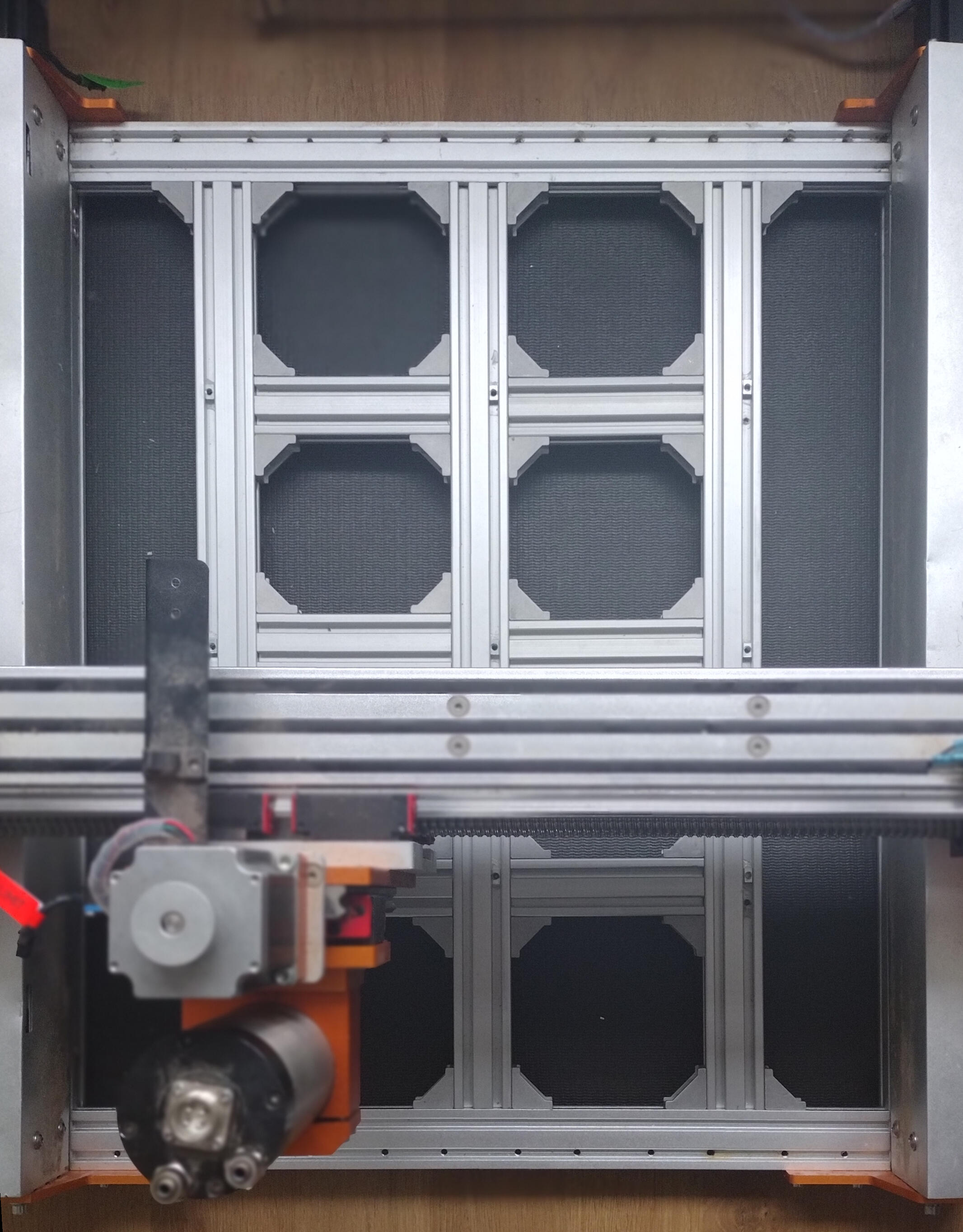
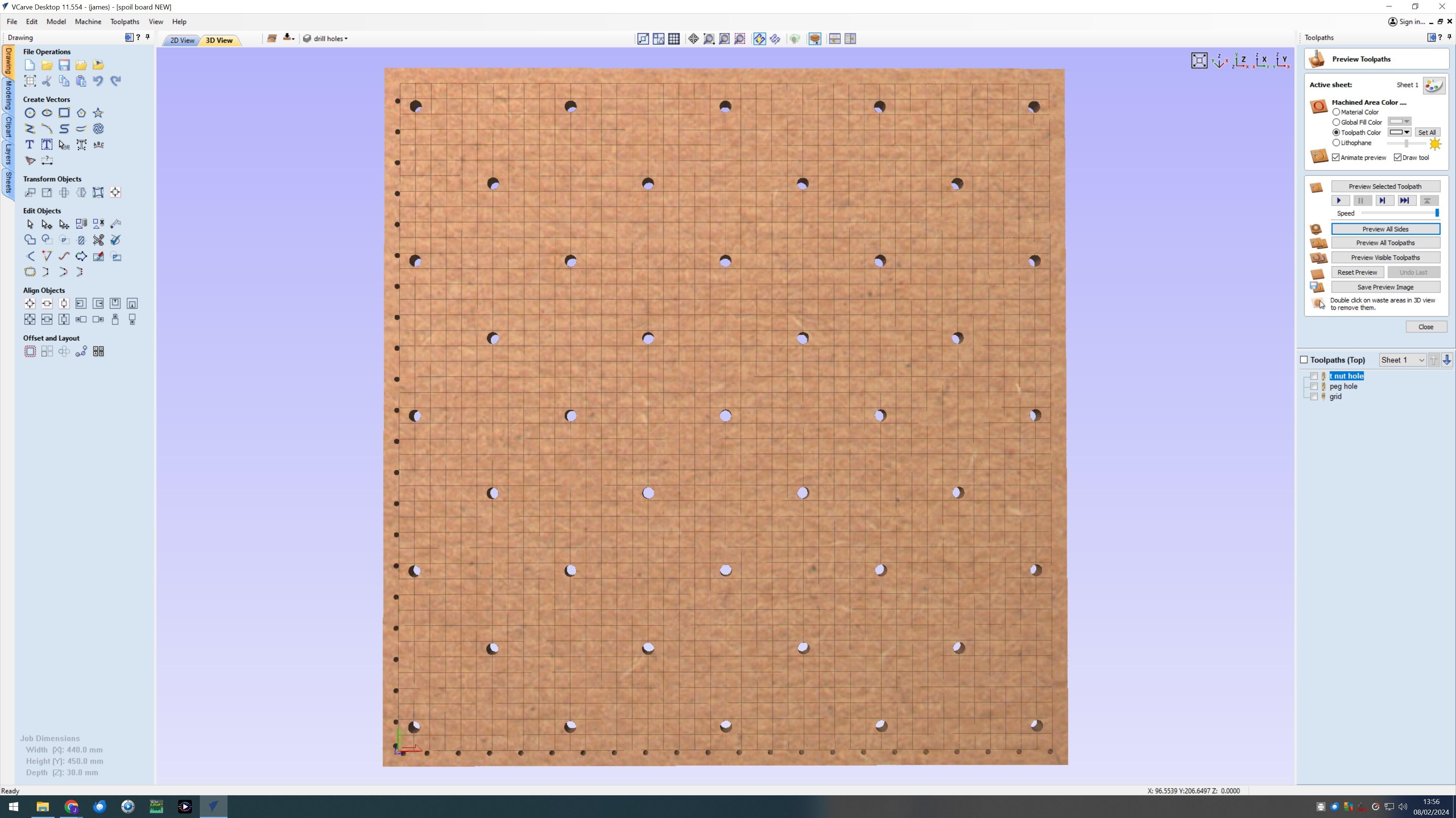
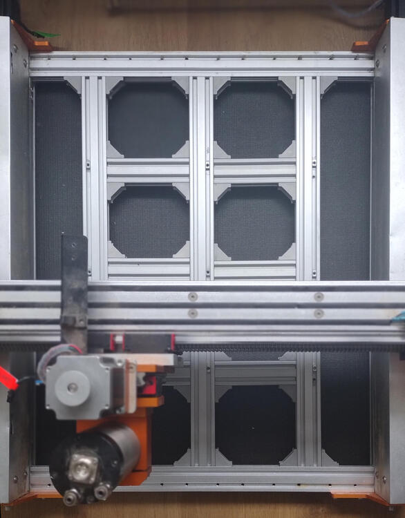
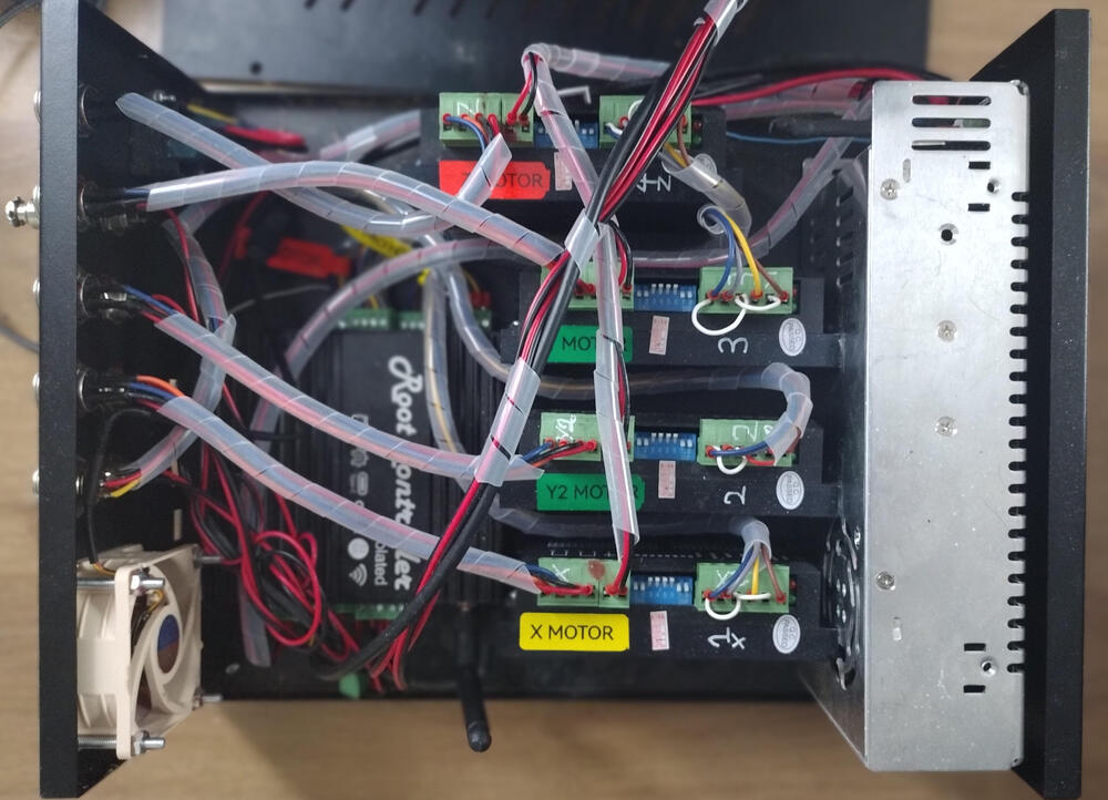
I thought I might post some of the modifications I have been doing to my Flox Alien vasto. I got fed up with the not so rigid spoil board and so filled in the bottom with 20mmx40mm aluminium extrusion... and replaced the thin t slot and mdf spoilboard with a 30mm thick mdf slab. The result is far more rigit and will take my own weight (60kg) with ease and no detectible flexing. The plan for the spil board is to have m6 threaded inserts on the underside of the board to allow me to screw in work holding clamps/brackets. A 20mm by 20mm grid engraved and a set of 3.175mm holes around the edge so I can insert small pegs to make lining up work with X and Y axis easier. I also got fed up with the cheapo controller. It has no rs485 support so it could not control my spindle vfd. I could not change spindle speed or direction in software. In fact the original unmodified machine could only switch on and off the cheap dc motor it was supplied with and had a potentiometer for manual speed control with no indication or rpms. It has no wifi support and no user interface, is also only 3 axis and completely undocumented. I opted to rip out the controller and put in a rootcnc controller (https://www.rootcnc.com/root-controller-iso-about/) running fluidnc (http://wiki.fluidnc.com/) control software. It took a while to configure fluidnc and re do all the control box wiring. I replaced the 2 pin spindle power socket on the back with a 4 pin to carry rs485 from the controller to the spindle vfd. I also removed the pause and resume buttons and replaced them with sockets for a tool height probe and a 3d probe. While I was at it I replaced the now redundant potentiometer that used to control the voltage on the original 48V spindle output with a fixed voltage divider of 12V so I could run a good quality noctura cooling fan and power diode lasers directly. I also got a cheap minbot labeller and went on a labelling spree. The result is I can store multiple profiles (one for the laser and one for the vfd spindle) in the controller flash, In fact rootcnc and fluidnc is versatile enough and has enough I/O I could run a vfd and laser at the same time if I could find a sensible way to mount both. I can control the spindle speed and direction in software and by using standard S and G3,4 and 5 gcodes, control the machine via the built in web server, usb or wifi and have much less fan noise, power 80W diode lasers directly from the control box and have 2 more axis. The spindle control and a spare axis makes an automatic tool changer such as the rapid change atc https://rapidchangeatc.com/ a viable option. I now have enough expandability that I could add control for a rotary axis, run a pendant or even consider automated tool changes... I have been experimenting with automated tool height measurement and have written some gsender macros to set the tool length offset using the tool height setter I recently purchased. I still have to manually remove and insert and screw down the tools but the aim is that I will then just press a button and the machine will measure the new tool height and Z axis work coordinate so the tip of the tool is at the same physical Z height as the previous tool. I chose the tool height sensor because it is also compatible with the rapid change atc.. Gsender has poor documentation for its macros so I got the source code and reverse engineered the macro language parser. I love open source software, if you can't find the information online you can always find it in the source code. The Z axis mount is too narrow to accept a mounting bracket for an 80mm diameter spindle. So at the moment I am stuck with 65mm spindles which limits me to only er11 collets and a maximum end mill diameter of 6mm. So when I have finished rebuilding the machine I will make a new zaxis mounting plate for 80mm spindle brackets and am looking at buying a 2.2KW er20 spindle with ceramic bearings and better dust sealing. Further in the future I would like to get the rapid change atc which will probably necessitate extending the y or x axis extend the x axis from 420mm useable to around 550mm or so. I'm also thinking about changing to closed loop steppers. happy cnc'ing James
-
That would be very nice, but, I suspect given the general behaviour of the human race, that there is a giant no fly zone around the sol solar system. I also think "humanity" probably has developed immunity to kindness/forgiveness. The story goes that the Argentinians could not get the Exocet working so as part of the support package they had several french advisors fly to argentina during the war to help them use them against the uk ships.... (https://theweek.com/world-news/falkland-islands/45704/bbc-finds-evidence-french-helped-argentines-sink-our-ships) remember it pays to pay for the support package
-
latest stax announcement: Due to decreasing sales of the sr009 we are discontinuing the sr007 since we don't know how to increment the price to make as much profit on it as the sr009 series. (We also forgot how to make spares and repair it cost effectively). We are proud to announce the release of the sr007a mk3. This release solves all the warmth issues of the previous sr007 models and benefits from the added clarity, detail and speed which made the sr009 series such good sellers. Please ignore the sr007 mk3's cosmetic similarities to sr009, we assure you the mk3 is a completely reimagined and redesigned sr007 brought into modern profit levels using modern technology for only $9000. Available now from all two remaining authorised dealers in Japan. Stax would also like to announce a new energizer to partner with the all new sr007 mk3; the srm007C rap using state of the art TPA3255 driving a 1:10 step-up transformer. The srm007C rap is manufactured under license by our new partners the IAG group in their mega factory in Shenzhen. It offers class leading efficiency for those who can't afford the utility bills associated with a valve design. Finally and terminally Stax would like to announce a collaboration with Blackstone private equity where Stax will rent back its manufacturing space from Blackstone in return for access to Blackstone expertise in increasing profitability and reducing manufacturing costs..
-
So Stax kill about the only good headphones they sell. Welcome to second-hand sr007 prices skyrocketing...
-
Well its not DC coupled (i.e. NO capacitors in the signal path) and it has a very low voltage swing - 200Vrms... due to the fact it has pre-amp tubes in its output rather than power tubes like the EL34. The bandwidth is not great and there is no distortion specifications at all (nothing vs output voltage and nothing vs frequency) which is a bit suspicious. I suspect the amp will have trouble driving Stax sr007. There is little information about the power supply but it does not appear to be fully regulated. As such it certainly does not look to be even close to a blue hawaii, mini T2 or T2 in specs and capability. Even the all valve Megatron has more voltage drive and almost certainly a better power supply. It is not known if the amp uses anode load resistors (bad) or constant current sources (good) for the output valves, but I suspect it's resistors. On the plus side it does not appear to have an output transformer... unlike some crappy comercial designs and does not require any DIY skills. However, if you don't mind building your own amp you can almost certainly make something substantially better (fully regulated power supply, fully DC coupled, constant current sources for the power valves etc) for around the same price.
-
perhaps your last post is exactly why no one else replied. I would like to see a long term solution to the entire Palestine problem. For your information I have never protested on the topic in question for either faction and have no desire to, its complicated mess and saying one side is exclusively right is impossible and unhelpful to a long term solution. I could call you a bigot for implying the UN and therefore, probably by extension, the entire world plus all universities is anti-Semitic but that would achieve nothing, but your words, do show your silo mentality which I am afraid to say is all I have experienced every time this topic has been discussed, my father has experienced similar as well and I am slowly coming to the conclusion this kind of experience might be widespread. I could be insulted by your words saying you expect me to protest in support of the palestinians or to remove my head from my arse, (If I could bend around that flexibly the climbing problem I got stuck on today would be a breeze). But I refuse to be insulted. I would say insults are the arguments employed by those who are in the wrong, but I dont think all you say is wrong. I am afraid to say that, in my opinion it is people exactly like you who make it so hard to feel any connection or sympathy for the Jews, but I try to keep an open mind, since, just because the proponents of an argument speak objectionably, it does not mean their argument is without merit. However, I have no desire to further engage with you on this topic or any other.
-
I'm sorry, but I am not sure what you are trying to imply. Just because no one comments does not mean that no one has an opinion (informed or otherwise) or that silence means that you are right or that everyone agrees with you or that there are not counter arguments to what you have written. The lack of comments could simply be that no one wants an argument with you (especially with your privileged role as a moderator), or start a flame war. If the protagonists on both sides in Palestine where equally reserved perhaps there would be fragile peace or even better a pathway to some solutions to the problems. Each side can point to the past, to past atrocities from the other side, atrocities that fuel more retribution and atrocities and naturally lead to attack is the best form of defense arguments. Until there is forgiveness and a willingness to not look at the past the deaths on both sides will probably continue at infinitum. International law says Israel illegally occupied the west bank (United Nations resolutions, including 446, 452, 465, 471 and 476 and United Nations Security Council Resolution 2334 of 2016 reaffirmed this yet again) and then illegally (advisory opinion by the primary judicial organ of the UN in 2004) built settlers homes on what amounted to the front line. If this had occurred elsewhere in a different context the international community would be sending an army to throw the occupiers out... Given this it is hardly surprising Hamas and the Palestinians also use the argument that the Israel is responsible for the deaths and that attack is the best form of defense. And so the atrocities and deaths continue on both sides, each blaming the other and each attacking the other and calling it defense and the human suffering continues.
-
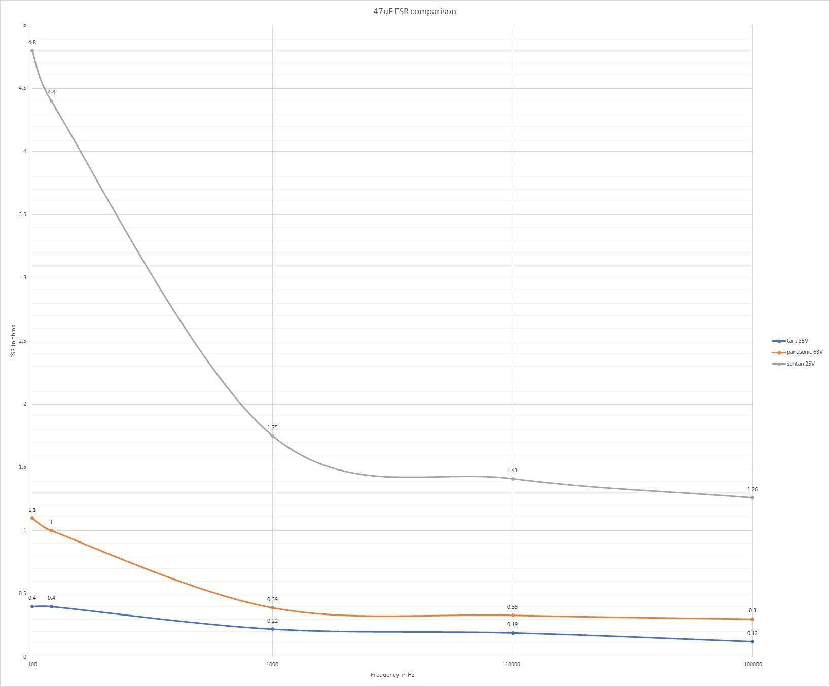
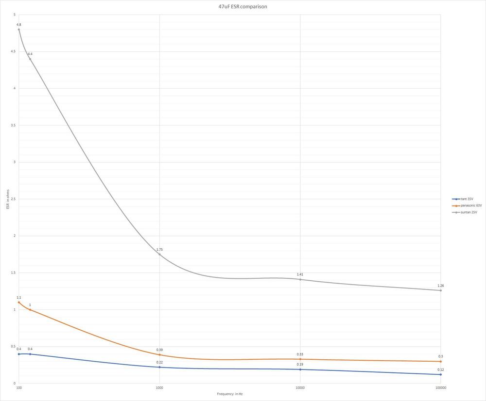
I just have a Mastech MS5308 Lcr-Meter. kemet 35v 47uf tantalum esr 100hz 0.4ohm 120hz 0.4ohm 1khz 0.22ohm 10khz 0.19ohm 100khz 0.12ohm panasonic 47uf 63V electrolytic esr 100hz 1.1ohm 120hz 1.0ohm 1khz 0.39ohm 10khz 0.33ohm 100khz 0.30ohm chinesium "suntan" brand electrolytic 47uf 105C 25V esr 100hz 4.8ohm 120hz 4.4ohm 1khz 1.75ohm 10khz 1.41ohm 100khz 1.26ohm so for this tiny sample size (and not the same voltage rating) tants have lower esr throughout the range I can measure. so not enough data points, resolution, sample size or frequency range etc. to make any real conclusions but maybe enough to start a electro vs tant thread...
-
I think tants typically will have lower effective series resistance at high frequencies than electros, and in general tants esr decreases with increasing frequency unlike electrolytics. https://www.doeeet.com/content/eee-components/passives/why-low-esr-matters-in-capacitor-design/
-
its possible that Q1 is only just providing enough current for the replay contacts to just about close resulting in poor switch contact - that might lead to noise. Also does the relay have a built in diode for transient protection when the relay switches state? If not the transients could be damaging Q1 and or the opamps.
-
I hope he is not using this multimeter. It has a built in transistor test feature so you know its quality.... resistance measurement only up to 2Mohm, and ac bandwidth of an insanely narrow 45hz to 450hz. 500V max input and is not even true rms... all for £2.95 before tax. https://cpc.farnell.com/duratool/d03046/multimeter-digital/dp/IN07220?mckv=s_dc|pcrid|426684131405|kword||match||plid||slid||product|IN07220|pgrid|100371162238|ptaid|pla-1751967123517|&CMP=KNC-GUK-CPC-SHOPPING-9262013734-100371162238-IN07220&s_kwcid=AL!5616!3!426684131405!!!network}!1751967123517!&gclid=CjwKCAjwu4WoBhBkEiwAojNdXqPLfzyh0bPlKygDGgTcWuNmZFHencRS08mstzeQNiGSrgSmFODsSBoCkpYQAvD_BwE 😬 💥 😱 🚑
-
a bit like a berk or a pillock but more nasty and very much like a Berkeley Hunt