jamesmking
High Rollers
-
Joined
-
Last visited
Everything posted by jamesmking
-
this stuff looks interesting Cermark Spray for making labels on steel, unfortunately does not work on aluminium- Starts at 25:32. marking aluminium with a lesser
-
A few useful basic CNC beginners videos I have found. calibrating axis setting up a spoil board. problem solving issues guide to bits some speeds and feeds for aluminium and steel - starting at 20min 20secs
-
Thank you Kerry. My plan, to begin with, is to modify existing hifi2000 cases and just cut holes for connectors and valve bases, do some engraving and more ventilation slots etc.. . I can't see myself scratch building a case any time soon, but I agree if I go down that route I will need more power and bigger tools. One thing that I am a little concerned about is the lack of software spindle speed control and I don't think there is a tachometer to tell you what the spindle speed actually is. But I guess I could get a hand held tach. I notice that most high power motors are water cooled. I wonder if I could use my pcs 480mm r(4x 120mm fans and 80mm thick) radiator 🙂
-
I could not help but notice that the dead tree carcass machinists have a thread on wood machining. But dead trees do not make the best cases for stax amplifiers. So i'm a little surprised that there is no thread dedicated to CNC machining metal. The motivation for this thread was that I turned 50 years old a few weeks ago and for my birthday I decided to buy myself a CNC machine so that I could make my own cases for my stax builds. I decided to buy the foxalien Vasto, https://www.foxalien.com/products/cnc-router-machine-vasto?sca_ref=725103.t6qfXeHAnx based on not much more than I needed to machine 400mm by 400mm and the reviews on youtube are very positive. I'm waiting for delivery so I can't comment on if it is any good and I am a complete CNC newbie so I'm hoping this thread might become popular and eventually contain some advice for people who want to build cases for their amps. regards and best wishes james
-
I have not ripped the telarc lps but I do have telarcs lps, cds and sacds issues of several classical recordings including the famous 1812 and the holst suites, Stravinsky firebird and pictures at an exhibition. I don't have a setup capable of playing back sacds without converting to pcm. I can bit for bit rip sacds. (hint early PlayStation 3 with early firmware could run alternative operating systems and could play sacds)... later firmware releases stopped this possibility and there is no way to downgrade after a firmware update. The telarc cd issues do suffer slightly from the down conversion... for example some of the cd issues do not use all 16 bits per sample. (My rme aes32e sound card has some analysis software and it shows the bottom 1 or 2 bits on some of the cd issues are not used and strangely the number of unused bits can vary between the channels!!). The sacd issues unfortunately do not give any details of how the conversion was preformed. Sound wise I find the lps more musical and a bit less muddled than the cds ripped to flac and played through my dcs elgar plus. However, there is not a lot in it and its possible that this is a limitation of the elgar plus - it was top end in its day but that was a loooong time ago. The sacd rips converted to 192K 24bit pcm do sound different to the cd, slightly less dynamic but more "cohesive" but this could be the effect of the dsd -> pcm conversion. Its also possible since the original recordings were 3 channel that they slightly tweaked the balance between the centre channel and the left and right to reinforce the centre a bit... Again the sacds don't give any details of any adjustments made to the mix... I have done transfers of my sheffield lab direct to disk lps - sheffield labs did release on them cd and I believe my recordings have better bass and more warmth and are more musical. The official issues do have a little more snap to plucked strings and possibly a bit better imaging. I run a highly modified garrard 401 with regenerative psu, upgraded bearings etc. But the official issue does have lower rumble than I can get from my garrard but the bass of the official issue is rather dry. If I run my recordings through izotope rx9 I can get rid of almost all the rumble and still sound better than the offical lp to cd transfers in the bass end. I suspect my cartridge is the limiting factor for the treble end. Running through the rme soundcards spectrum analyser I can see a fair mount of music above 20Khz in the lps which is cut off by the cd brick wall filter it looks like they did not low pass filter at 20k when doing the direct to disk. Extension past 20k varies from disk to disk - confederation does not have a lot, however the three Harry James lps have quite a bit due to the harmonics in the trumpets and brass instruments in general, cymbals etc. I am really sensitive to bass quality and I almost never play the official cds - I play my lp transfers. I also have also recorded some of my opus 3 lps and compared to dsd downloads available from dsdfile and in a few cases the offical opus 3 cd issue. (dsd file got the original master tapes and went direct to dsd) here my lp rip setup to the dcs 905 adc can't complete with dsdfiles' top end tape deck playing the original masters - the dsd macro dynamics are better, stereo imaging is better, treble extension is better and snappier, bass is deeper and more solid. Again there is some output above 20khz on the lps and dsd but it falls off above 20khz fairly rapidly which I guess is just the response of the analog tape deck used in the original recordings or possibly some mild low pass filtering. The potential problem with telarc sound stream onto dsd is, yes sacd has a higher sampling rate than cd but dsd has lots of high frequency noise which either need to be filtered on playback or "ignored" - if your playback system has little bandwidth above 20khz. Secondly you still have do do maths to convert from soundstream to dsd- the bit format for sacd and so will not give you a bit for bit copy of the original. I can't make a fair comparison of the cd vs lp vs dsd sound since my setup in London does not have native sacd support and so I reply on Jriver media player converting my sacd rips from dsd to 192K 24bit pcm. I do have a dsd capable dac - dcs elgar plus, but it can only do dsd via 3 bnc connectors and I dont have anything which can take sacd and provide that output (ironically my dcs 905 adc also supports recording dsd and has the same 3 bnc output). The rationale for sacd/1 bit recording was that you don't need to brick wall filter during recording and that its these filters that damage the sound. The filters cause phase shifts and also almost all symmetrical filters have pre ringing - i.e. echoes of the sample before the sample is played. However, with dsd you still need filtering on playback... In fact both the dcs elgar plus and dcs 905 adc have selectable filters for pcm and dsd for playback and record respectively. Considering non audiophile labels for example the Philips remasters of 1970s classical music - e.g. Marriners complete Mozart symphonies vs my lp transfers there is absolutely no contest. Many of the official cd transfers where from lp - if you spectrum analyse you can see low frequency warps and you can even hear the occasional click and pop of dust. The cd transfers from philips have awful treble, glassy, hard and "stringy" typical early cd sound - are lean, lack of bass almost no warmth. This is particularly bothersome with some of the early symphonies that are mostly just strings and the result is the cds are bit painful to listen to. My Lp rip vastly more musical and better balanced. Philips uncaring cd transfer vs careful lp transfer sound as different as stax sr407 vs sr007. I have not riped any of my lps to dsd for the simple reason I have no ability to edit the results without converting to 192K 24 bit pcm editing in pcm and converting back - which is not a bit accurate conversion... however unfortunately this is how many dsd recordings are edited. The dcs 905 also has the ability to do 384Khz but this outputs in a special format for a certain nagra digital recorder and I have not bothered to write any software to convert nagra 384K to pcm 384K although it should be possible and should be bit for bit accurate since the nagra simply spreads the stereo 384K over 4 192K channels as it does not have enough bandwidth to record 384K on two channels.... but I don't have a dac which can do 384K anyway. So for me, my general feeling is: well made original recordings on tape transferred expertly from the original masters to sacd or cd would require a ridiculously expensive lp setup to rival - definitely £20K+ for cartridge, arm, deck and phono stage even without factoring in the adc. Mass market classical cd issues of analog recordings different story.
-
the telarc recordings were half speed mastered with no transformers in the signal chain and a frequency response down to 12hz or so with no compression or limiting or any type. They tried to get the entire signal chain as high quality as possible and muck around as little as possible, right down to using only using 3 high performance microphones and not multi milking, spot lighting etc. They designed for proper hifis and not for the average consumer grade kit. The soundstream digital system also sampled at a higher frequency than the competition (or cd), and unlike early cds, telarc could actually do editing and splicing digitally whereas all the major record companies took the digital recorded it onto analog tapes edited the analog tapes and then played the edited tapes and digitally re-recorded (but still lied and claimed the signal chain was DDD throughout)... or recorded on their didital system and then converted to soundstream edited and then converted back. Even when DAT and proper computer editing took over the sample rate was higher than cd and had to be down converted and anti aliasing filters applied... the stream of data off cd also has a delay between the right and left channels. many early cd players did not correct for this which I think was one of the reason the treble was so sharp on the early cd players. A few high end players ended up having two dacs and a time delay circuit to realign the left and right channels. But I never got to hear one at the time. In many many cases the record companies transferred analog masters to DAT, and then threw away the analog master tapes... DAT had almost no error correction built in and a few years down the line the DAT tapes were unreadable and the master tapes were gone. So many of the cd reissues of classic analog recordings where actually digital recordings from the lps anyway, and the lp system they used for play back was garbage, the "remasters" sounded bad then and they still sound bad now. I could make far far better recordings from my lp system going through a dcs 905 adc at 24 bit 192Khz sample rate. Telarc digital on lp vs philips "remasters" of classical lps on cd... no contest. I played the telarc 1812 no issues on a decca black with decca pod, modified tie wire system and a proper line contact diamond. My ortofon cadenza bronze has no issues either and thats a moving coil. Both on a heavily tweaked haddock 242 unipivot arm. (ALL hadcock 228 arms had incorrect geometry and the aluminium arm tube versions lack the weight to properly press down on the inverted uni pivot)). And of course ALL telarc sound stream recordings have to be down sampled and anti aliased to go onto cd... The sound stream digital was far better sounding than the early Philips PCM - which DID NOT have even 16 bit resolution... it was about 12-14 bits + deliberately added noise because the 14 bits was not that linear and low level signals had about 25% - 75% distortion and looked like square waves.. apologises for incoherent rambling but for me the message from sound stream was make the record chain as good and simple as possible, make as few compromises as possible and don't muck up the sound with filtering or compression and aim for an audience with proper hifi... lessons many recording companies never learned and still need to learn today. I also wonder if the average person listening to music through their mobile phone gets higher auto quality than the average person in the 1960s or even 1950s... (when a good hifi seemed to be a part of most middle classes lives). I have listened to a friend playing some music through some cheap Bluetooth speakers via their mobile and I seriously wonder if (apart from the surface noise) the sound was better than a 1940s 78 on a good player. James
-
if you are using a multimeter with a 10Mohm input impedance then you will not measure the actual voltage. The stax bias output is very high impendence i.e. provides very very little current and so even the current draw of a 10Mohm multimeter will load down the bias and you will measure lower than expected. Either you need a meter with a Gohm or higher input impedance at 1000V or you need to measure before the current limiting system on the bias output. For example the golden reference HV power supply bias circuit has a 4.7Mohm current limit resistor just before the output so you need to measure before that limiting resistor and of course be careful because if you multimeter can't handle 580V or you touch the probes etc you will get a non-current limited 580V DC shock which is not going to be good for you. incidentally I get about 378V DC at the socket on my diy T2 (pro bias only) into a 10Mohm meter BUT this value is going to be very dependant upon the value of the current limit resistor in the bias circuit. So if you amps current limit resistor has a lower value then 420V is not necessarily unrealistic.
-
I dropped a valve on to a hard wooden floor and although it looked intact the insulation between the heating element and the cathode was damaged. (I checked it on a avo iv valve tester and it had <1Mohm insulation heater to cathode) it was even possible to see a little of the white insulation lose in the bottom of the valve. So this is one possibility.
-
The user interface on macrium is not as intuitive or as pretty as acronis, and I cant cmopare the tech support because I never needed marcium support. My general feeling is that marcium is still a focused product. The only "security" thing Macrium does is that programs outside of macium cant delete or modify the back files you create with macrium.. which is sensible and ithis protection feature can be switched off.
-
I used to be a long time user of acronis true image more than ten years... I even was on their beta test program for a number of years. In my opinion acronis got worse and worse after about 2015/6 as a product and a company - I believe they got bough out by a venture capital company. Basic things were either removed or did not work e.g. you do differential backups. There was no way to delete a differentials from inside the program and if you deleted one from outside the program the index files messed up and you could literally get hundreds of error message popups one after another all saying could not find file x. The tech support in the forums basically stopped replying to peoples complaints - I must have complained for about 4 ot 5 years before they put deleting differentials back into their software. Then acronis decided to start offering yearly licenses automatically renewing and added pay per year per GB cloud and anti virus into a backup program rather than fix the backup program they had, then they decided to go pay per year rent only NOT even allowing existing users with permanent licenses to buy more licenses for the software they already had full licenses for. At tis point I jumped ship to macrium reflect just as Acronis did a product rebranding exercise rather than fix the things people where complaining about... Their backup software did not even allow you to select your own drivers from your own windows install so if you had fancy network cards, host bus adapters etc your recovery image had no support so you could not recover. There was no bit locker support so if you had bit locker encrypted drives you could not read them from their recovery medium.. it took an acronis forum member to write scripts to inject drivers and bit locker support to make the recovery medium actually useful to recover with because acronis could not be bothered to do it themselves.. In my opinion without the forum contributed scripts acronis would have been abandoned long before their product lost focus and became pay per year only. In my personal experience acronis lost the plot... just look at the stream of complaints in their support forum... macrium reflect on the other hand allows you to select drivers from your existing windows when you build recovery media, allows deletion of differentials and the recovery medium supports bit locker out of the box and is still buy once own forever.. They also dont seem to bring out a new version every year with lots of useless features.
-
just XOR each byte of the data with binary 10101010... The algorithm is extremely fast to both encrypt and decrypt, is one of the few encryption systems that takes the same time to encrypt as decrypt, the encrypted data is no larger than the original data It does not rely on a "random" number generator backdoored by the NSA to be predictable. It is also one of the few encryption algorithms that is exportable without a license and can be used in products sold to countries such as North Korea. Almost all processors implement XOR in hardware providing hardware accelerated encryption the algorithm is simple enough to be implemented on 8 bit and 16 bit architectures providing true cross platform portability and compatibility. To make the encryption key more difficult to guess it is optional to rotate the key by 2 bits to either the left or the right i.e. 10101010 -> 10101010. Implementing the key shift does not break compatibility with systems that don't bit shift the key, this is true even if the data is encrypted on a system that left shifts but is decrypted on a system that right shifts the encryption key. Similarly deciding when to do the shift e.g. after each encrypted byte, after a block of encrypted bytes or after a certain time does not break compatibility with systems that implement a different algorithm for deciding when to shift the encryption key. It is even possible to make multiple copies of the key and encrypt the key with the data and still maintain compatibility with systems that encrypt the data with the key.. it is possible to increase the size of the key in 2 bit increments to any size up to the length of the data being encrypted allowing for keys far larger than supported by AES, DES, etc. Encryption key distribution is often a weak point in a system especially if the key is sent over untrusted networks like the internet. With this algorithm it is totally unnecessary to provide the receiver with a copy of the key, avoiding key distribution entirely. If you forget the encryption key you can recover it by XORing a copy of the unencrypted data and the encrypted version Overall the advantages to this algorithm are considerable.
-
Like most pre-amplifiers the blue hawaii topology is actually an attenuator followed by fixed amplification stages. (in the case of the blue hawaii totalling x1000 times gain). The amplification stages will amplify by a fixed amount regardless and independently of the blue hawaii volume control. The blue hawaii volume control simply reduces the input voltage before it is then amplified by x1000. This means any noise on the inputs will also be multiplied by 1000! if you bypass the volume control so you need a quiet pre amp and sources. One thing to be cautious of is, when you switch off anything connected to the inputs of the blue hawaii if thing being switched off creates a thump or generates a dc offset as it is shutting down the blue hawaii will be multiply it by x1000 and sent it to the headphones... THUMP! SIZZLE! So its highly recommended to have the blue hawaii volume at full attenuation before you switch anything else on or off. You can get a similar situation if you switch off a preamp before switching off the power amp in a loudspeaker setup. Other than this their should be no problems and in fact some forum members have built blue hawaiis and similar without volume controls in them.
-
I think you might be correct, mouser has it as end of life, but on semi does not and none of the other usual suppliers do. Hopefully mouser is wrong. So hopefully it is not EOL..
-
I just sent him a private message on this forum. I told him that I wanted them for a mostly modern T2 build and that I just needed a few - enough to build one amp and a set of spares in case the build went wrong, and was not going to resell them for scalper prices on ebay....I suspect he might be less inclined to supply if the intent was to resell - especially for a profit.
-
I have purchased 2sk216 and 2sj79 from spritzer for a mostly modern t2 build. The prices might not be cheap compared to the price of the transistors when still in manufacture but they are now increasingly rare and the market is flooded with fakes. You are getting genuine parts if you buy from Spritzer - unlike pretty much every seller on ebay which are selling fakes and ebay does not give a care.
-
I wonder if it would then be possible to use the redundant quad esl audio step up transfers in reverse to step down the 4cx250 output voltage so it can drive conventional headphones and/or conventional speakers making the amp totally universal: drives quad esl, drives stax without the step down transformer, drives conventional headphones or speakers with transformer.... drives everything SPLAT
-
-
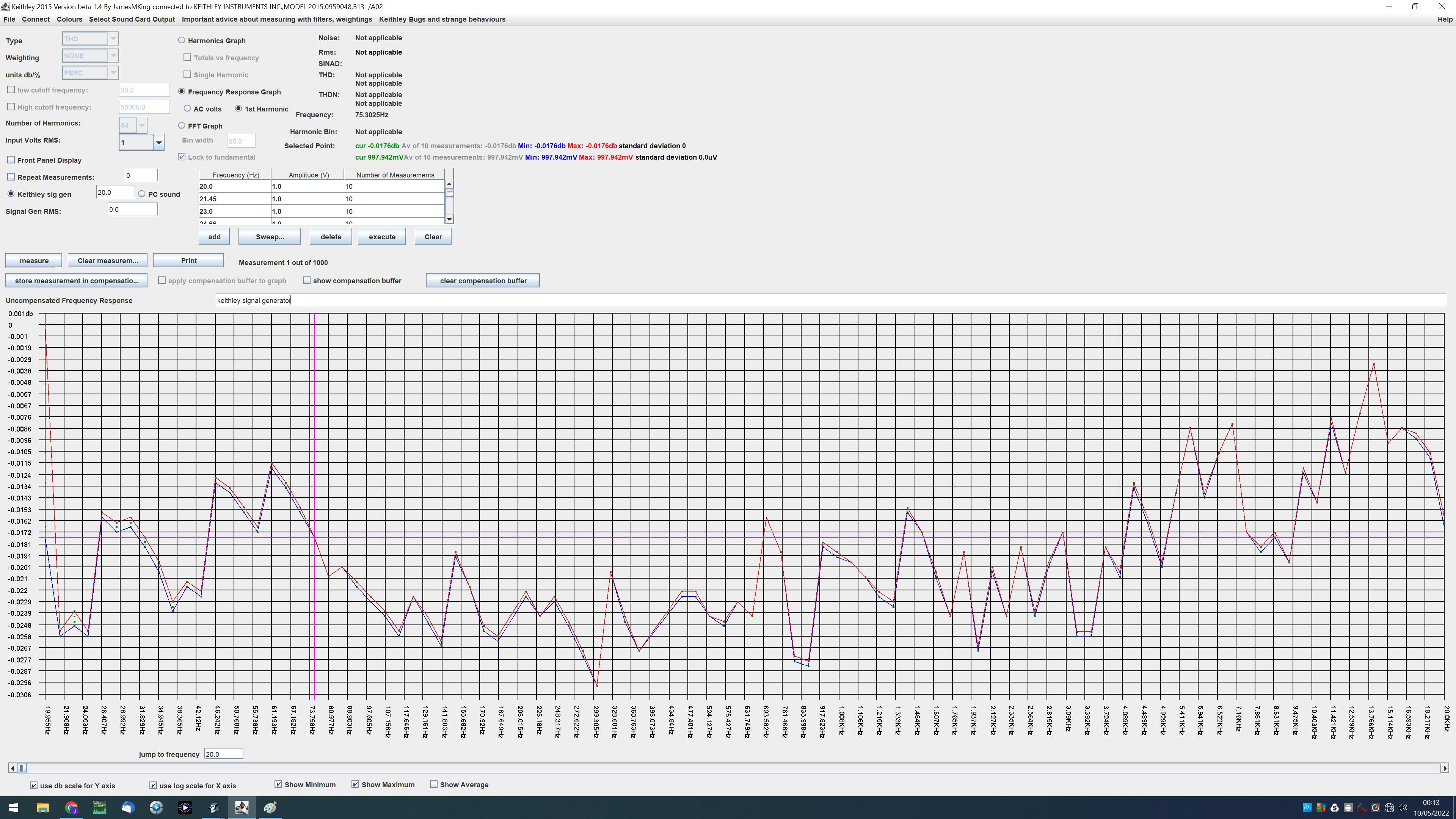
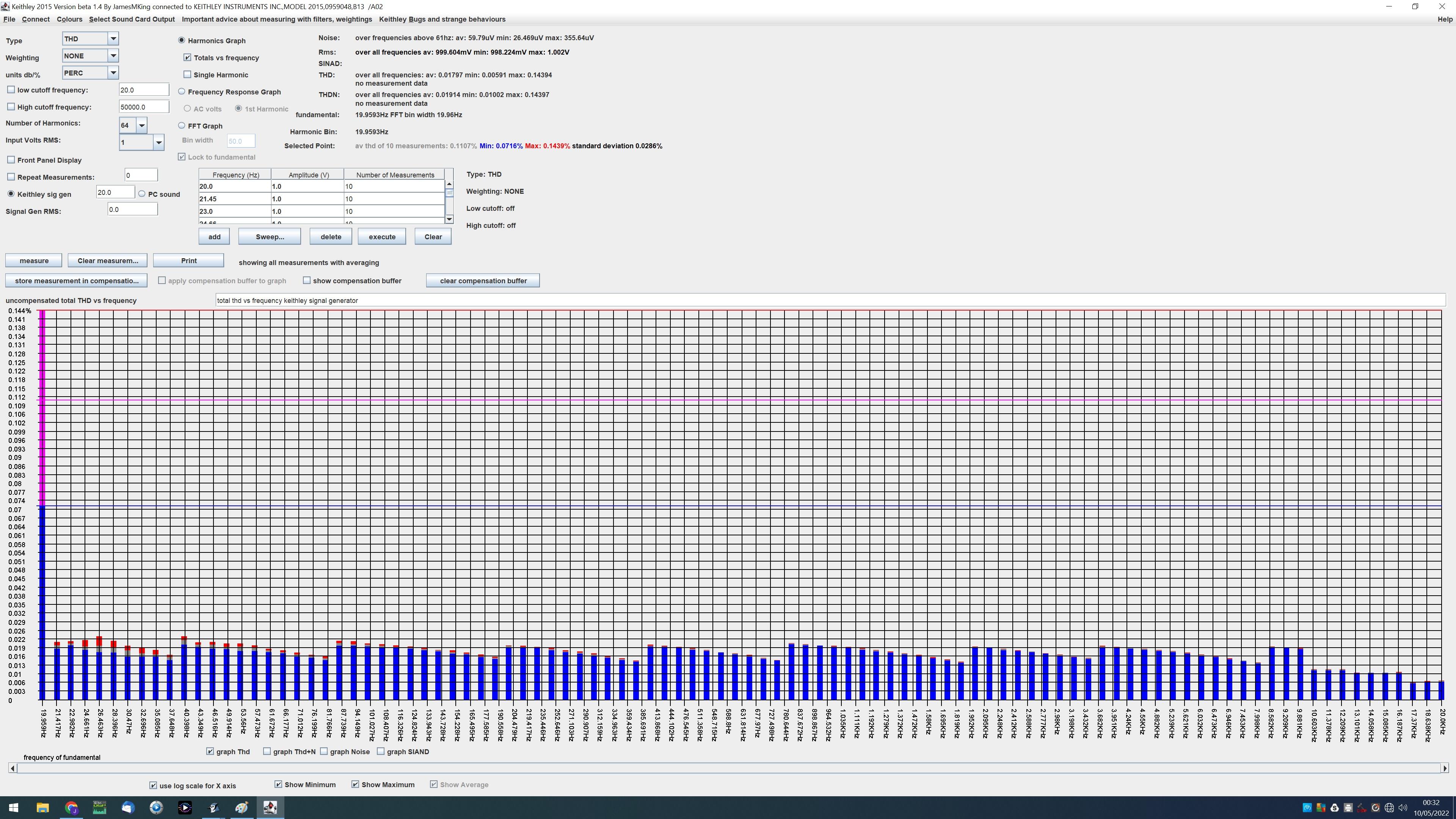
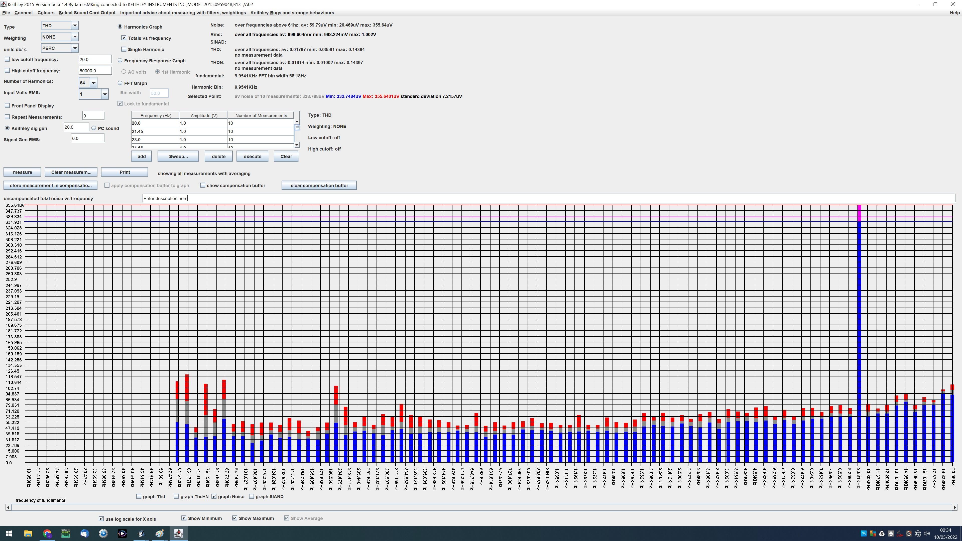
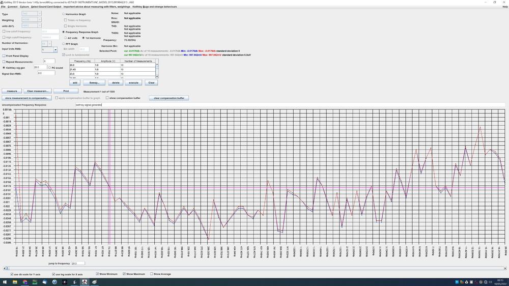
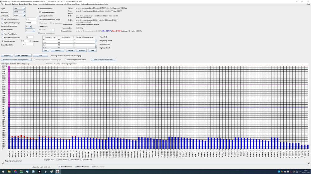
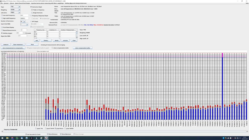
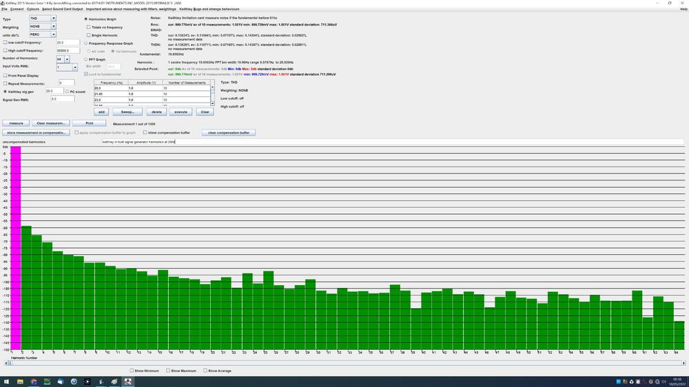
This is a very niche topic so if you are not planning to buy or write programs for the Keithley 2015 or 2016 thd or p multi-meters then this post will probably not be interesting to you - especially given their skyrocketing prices on ebay and their age. If you are planning to buy one because it has audio analysis built in then there are a number of limitations and issues you should be aware of before deciding to buy. Some of these limitations effect the accuracy and validity of its calculations and are not documented in the manual, some of the limitations effect usability and some effect it programmatically if you access it through gpib or rs232. If you look on the internet there is very little software written for these meters and you may be wondering why. Well now I have written some software for them I think I have a better idea... Here is an example of the "quality" of the manual "The Model 2015/2015-P/2016 can use up to the 64th harmonic of a signal (64 times the fundamental frequency) in the THD measurement, but only recognizes frequencies below 50kHz. Harmonics with frequencies above 50kHz are ignored, therefore acting as an adjustable lowpass filter." What do you mean by use? are the ignored harmonics included in the background noise measurement? or are they simply ignored completely? Well it turns out thd+n included the harmonics as does SINAD. ( I'm still trying to determine for background noise since my calculations do not match the Keithleys). Similarly the statement about the upper frequency is ambiguous for multiple reasons. Bellow 50khz is included and above 50khz is ignored... what about exactly 50khz? more importantly what about a harmonic bin that starts before 50khz but ends after 50khz? or has its centre frequency at 50khz? The 50Khz limit is NOT adjustable and is absolute. There is a separate low pass filter which is configurable and can be switched on and off. Once you dig into the detail the descriptions in the manual leave more questions unanswered than answered. Limitations the in built signal generator goes from 10hz to 20khz only and is flat to within only 0.02db it also has a noise spike at 10khz average noise is about 50uV noise spike is more than 350uV.... thd measurement is limited to a maximum of 64 harmonics. This means if you are measuring the thd a 20hz input, the bandwidth of the thd measurement tops out at 20hz*64 harmonics i.e. way bellow 5khz.. However, Sinad and thd+n not limited to 64 harmonics.... this is obviously inconsistent behaviour and if the harmonics higher than the 64th are large in magnitude then the thd will be underestimated but the sinad and thd+n will be good... it is possible to limit the number of harmonics calculated in the thd to less than 64 using the front panel or programmatically but this does not effect sinad or thd+n calculations. But if you do limit the harmonics and then programmatically ask for all the harmonics any above the limit are not returned - they are lost forever. thd cannot be measured for inputs bellow 20hz or above 20khz all audio analysis is bandwidth limited to 50khz or lower (in some cases the bandwidth limit is 20khz due to the limited number of fft bins) and it is not possible to get the actual bandwidth limit via the front panel or programmatically. If you want to know the upper limit you have to reverse engineer its behaviour - the behaviour is not documented. The fft and harmonics are bandwidth limited to 50khz so if you measure a 20khz fundamental thd is calculated on two harmonics only and one of them is the fundamental! the fft bin width automatically varies depending upon the input signal fundamental frequency for example at 20hz the bin width is 20hz at 1Khz the bin width is 66.6 recurring hz this is not documented and must be reverse engineered to workout the relationship between fundamental frequency and bin width. This is made more difficult when: it is NOT possible to get the bin width displayed on the screen of the keithley or get the bin width programmatically. it is not possible to get the starting or ending frequency of a bin it is not possible to get the number of fft bins used in the thd, thd+n, sinad or noise calculations it is totally unclear from the manual if the rms value for the signal returned in audio analysis mode is the rms value of the entire signal, the signal plus harmonics or just the first harmonic. The manual simply says the result will be different from measuring the ac volts value of the input... Extensive experiments seem to indicate it is the rms of the 1st harmonic. The slowest part of a program communicating with the Keithley is transferring the fft bins especially using rs232. But the keithley does not provide a way for you to obtain the number of fft bins which contain valid data so you have to get all the bins. This increases an fft transfer time by up to 25% (in the case where bandwidth limits the number of valid bins) compared to only fetching the bins with valid data and the situation is far worse if weightings or low and high cut filters are used. you can improve performance across the gpib bus by setting the keithley to transfer floating point numbers rather than number in their text representation however not all measurement returns actually support this so you have special cases all over your program to determine if it should be reading a float or the ascii representation of a float. The manual is also not accurate ascii rather than a float is returned in float mode. If you apply a weighting filter such as C-message which only has a bandwidth from 60hz to 5khz the keithley does not reduce the fft bin width to provide higher FFT resolution. As a result, a 1khz input FFT with C-message results in only 300 valid bins out of 1023 and uses a bin width of 66.66hz when the keithley could have chosen a bin width of 33.33z and doubled the resolution.... or picked a bin width of 20hz and triple the resolution. The weighting filters have brick wall filters attached which is not documented in the programming and user manual. However a promotional document for the keithley does have graphs for the weightings but the actually implemented brick walls are not consistent with the promotional material graphs for CCIR and CCIR/ARM. Experiments show the brick walls are at: CCIT low cut 50hz high cut 5khz CCIR low cut 31.5hz high cut 20khz - this is not consistent with the keithley promotional documentation which shows the weighting graphs and shows CCIR extending to 30khz CCIR/ARM low cut 31.5hz high cut 20khz - this is not consistent with the keithley promotional documentation which shows the weighting graphs and shows CCIR extending to 30khz A weighting low cut 20hz high cut 20khz C message low cut 60hz high cut 5khz It is not possible to get the rms value of a harmonic or fft bin - the only option is to get the result in dbc relative to the first harmonic/fundamental frequency rms value. there is a limit of 1023 fft bins as well as a bandwidth limit of 50khz which means some measurements are only performed on around 735 bins because the bin width is large for example 68hz and more than around 735 bins exceeds the 50khz bandwidth limit - the keithley does not try to minimise the bin width to maximise the resolution and the algorithms used are not documented. As a result at input frequencies bellow 50hz you run out of bins before you reach 50khz and above 50hz you run out of bandwidth and lose bins. The bin width behaviour is very dependant upon the fundamental frequency and so two frequencies close to each other can result in radically different bin widths. you can manually set the bin width BUT if the largest input frequency is not a multiple of the bin width the FFT analysis produces poor results. for input frequencies bellow 61hz the bin width equals the input frequency i.e. all fft bins are harmonics so measuring the noise is impossible since there are no noise bins... However, at least with my firmware, the keithley reports a bogus noise value for frequencies of 60.8 to 61hz even though all bins are fundamantals. there are multiple features which you can only access programmatically: noise measurement (only for input frequencies above 61hz) fft bin values low and high cut filters The keithley has a programmable capture window for acv measurements. A too long window results in slow readings, a too short window results in errors in calculating the frequency of the signal. This capture time is NOT programmable in audio analysis mode and is set to a too short value for low frequencies and results in frequency measurement errors at 20hz to about 30hz resulting in incorrect ffts and high distortion values The signal generator is not particularly low noise or low distortion - about 50uV noise at 1V output and about 0.02% distortion (1khz 64 harmonics). My pc sound card analogue output managed almost an order or magnitude lower distortion when measured by the keithley. The programming manual is misleading and varies in quality and detail from section to section. For example equations are provided for thd, thd+n and sinad but not for its noise calculation or its weightings e.g. A, C-message, CCITT etc. Nowhere does the manual mention fft bin width or number of bins varies with fundamental frequency or provide the equations to work out the number of fft bins or fft bin width for a given fundamental frequency - and reverse engineering this was complicated the algorithm changes 3 times over the frequency range 20 to 20khz... For thd, thd+n and sinad I implemented the equations in the user/programming manual and came up with identical answers to the keithley to around 8 significant digits - the rest being rounding errors. For noise I assume all valid non harmonic bins are noise but my calculations do not match the Keithley... I get around a 1% underestimate so the keithley is finding extra noise from somewhere! But my thd and thd+n calculations match the keithley. If I calculate THD+n - thd should just be the noise and this matches the value I get from calculating on all valid bins minus the harmonic bins and still does not match the keithley. If the keithley was finding noise from somewhere then my thd+n calculation should not match the keithley. I.e. the keithleys (thd+n - thd) and noise calculations are not consistent with each other. Sinad also takes into account noise and again my sinad calculations match the keithleys. The keithley has built in averaging but can only apply this to the thd measurement and NOT noise, sinad, thd+n, fft or harmonic measurements. The keithley uses the SAME command to inform it of the fundamental frequency as it does to set the fft bin width (if you choose to hardwire the binwidth)! This has the effect that if you hardwire the bin width the keithley thinks that value is also the value of the fundamental frequency! it is also not possible on screen or programmatically after the fact to separately get and disambiguate the set hard wired bin width from the fundamental frequency - again the same command is used to get both! if a low or high cut filter cut off frequency is part way into an fft bin the fft ban is not excluded. This is not documented. However possibly my biggest issues with the keithley is that it appears that it does not store raw measurement values and then apply filters, weightings sinad, thd thd+n calculations. Instead it stores the final processed values so there is no way to undo a setting or examine how a setting effects the result. For example if you set a low or high cut filter this effects all calculations. Harmonic bins and fft bins excluded by the filters are lost forever and can not be recovered... changing absolutely any setting invalidates the current reading and requires a new measurement to be taken! i.e. you cant change the weighting filter, cant change the low or high cut filters, can't change the measurement type from thd+n to sinad or vice versa, can't change the number of harmonics included in the thd calculation can't even change the returned thd and thd+n values from db to percent or visa versa. Absolutely any setting change results in you needing to make a new reading. To summarise The signal generator is poor, audio analysis is difficult to control, difficult to understand how it works under the hood, has multiple low frequency measurement limitations, only saves processed values is missing multiple commands for getting useful information about fft bins and has poor documentation on the detailed workings and interactions between settings - especially when multiple settings effect a calculation. Conclusion The keithley hardware is not an audio percision on the cheap. I don't know if any of this will ever be useful to anyone, but I have said it now - perhaps this is more or a rant because of the amount of time and effort I have had to go through to reverse engineer its behaviour and algorithms. If you are insane enough to want to write program(s) for the Keithley I can provide you code for calculating the bin width vs fundamental frequency, number of expected valid bins returned vs fundamental frequency, etc. P.S. AC current limitations the 2015 and 2016 also only have two ac amps ranges 1A and 3A so they are not great choices for low current ac measurement. In contrast the older and more humble keithley 197a has a AC current ranges from 200uA to 10A! here is the frequency response of the keithley signal generator100 frequencies log sweep 10 measurements per frequency. notice at 20hz the standard deviation is almost 1mv on a 1v output and varies by 0.015db over the 10 readings . This is not the signal generators fault - it is a issue with the way the keithley measures frequencies bellow 30hz in audio analysis mode. If you measure in ac volts mode almost all of this variation is gone here is the total thd vs frequency for the inbuilt signal generator. Again notice the disproportionally high thd at 20hz (10 times that of 1khz) and large variations in the 10 measurements min reading at 20hz 0.07% max at 20hz 0.14% at that frequency: The+n looks simular and other signal generators feed in to the keithley also show high 20hz thd and thd+n results. and the harmonic analysis of the 20hz measurement: and the noise vs frequency with the 10khz noise spike:
-
stax headphones are naturally balanced. There are two grids that high voltage audio is sent to. Between the grids there is a very thin statically charged sheet. To make the sheet move correctly one grid most have the opposite audio to the other so that one grid attracts the sheet while the other repels. If only one grid had audio (single ended output) the electric field created by the grid would drop off with square of the distance from the grid. So when the sheet is repelled it would move further away from the grid and be less effected by the voltage on the grid resulting in a loss of linearity. With two grids opposing each other the effect of moving away from one grid is directly counter-balanced by the effect of sheet moving closer to the other grid as well as creating a much more uniform electric field between the two grids. Thus maintaining linearity and improves efficiency - the same effect happens in electrostatic loudspeakers. So to drive the stax properly you need a balanced output. there are of course other advantages to balanced such a greater immunity to noise, longer permissible cable lengths, common mode noise cancellation etc etc. for the input to the Stax amp you can use single ended or balanced, however the single ended has to be converted to balanced at some point... disadvantage to balanced you need twice the amp components (excluding power supply which is usually shared between + and - halves of a channel)- if the amp balanced all the way through and probably a phase splitter to provide support for single ended inputs to the amp.
-
the main reasons for an external supply are 1. you are worried about induced hum from the transformer(s) 2. you simply can't fit the power supply in the same case as the amp It is perfectly possible to build a complete blue hawaii with golden reference power supply boards, shielded transformer, high voltage delay etc into a single 400mm deep case saving money over buying two cases and the fiddle of creating a cable run between the psu and amp... I did this in my build. building an amp (if you have the skills, time and test equipment) is considerably cheaper than buying one pre made...
-
drive for the sr007a mk2. I'm sorry I cant comment of the x9000s but if they have simular drive requirements to the sr007mk2 then they are going to sound awful with an underpowered energizer.... I ran the sr007mk2 (very power hungry) on srm006t mk2 - (one weak 6cg7 per channel) and the result was awful, muddy bass that did not get louder as you increased the volume - it just got even more muddy and indistinct. No bass detail no bass extension, poor macro and micro dynamics overall a very unsatisfying sound experience with jazz and classical music. Soundstage lacked air and it was impossible to tell what magic the sr007 would provide when driven properly. Tube rolling did little to help since the problem was lack of drive and all the same design tubes had approximately the same drive. I could effect the treble changing tubes but the bass changed very little. Trying to "improve" the bass elsewhere did not work because the underpowered energizer just could not deliver the bass to the earspeaker anyway. In going to something with 2 EL34s per channel, fully regulated power supplies and constant current anode/cathode sink and sources like the T2 is necessary to get the best out of the 007s and is revelation in sound quality. regards James
-
I am afraid don't have any experience of the T1s, or ecc99. Constant current is going to help the T1S. My guess would be that the high amp psu is better but in the forum people have reported considerable sound quality upgrades moving from resistor load to CC so the T1s with CC would probably be better than the Antares. T1 with CC vs Centauri (centauri is two 6sn7 per channel so more current potential and runs high voltages too) so more difficult to predict a winner. (some of the other forum members like spritzer have massive amounts of experience and would almost certainly be able to provide more solid info than I can from guesswork). some of the choice is going to be down to what you want the amp for... do you want something pre made and plug and play, or do you want to modify an existing T1s or do you want to have a go at building something fairly simple from scratch, plus it depends on your budget.
-
I have not tried the Antares, but I did build an alpha Centauri... which was my first even stax amp build. All of the high-amp designs are similar in that they use resistors for the anode load rather than a constant current source and have relatively limited voltage swings. The high voltage power supplies are ok - they don't use a precision voltage reference like the golden reference series but they are better than the supplies found in most(all?) of staxes offerings and they have very good short circuit protection and robustness. The headphones bias is regulated (unlike most/(all?) of staxes offerings) and correctly has a ~5Meg ohm current limit resistor and is the correct 580Voltage too. Overall I would say the designs are competent but certainly not for state of the art. I did find a few errors in the schematic and gerbers for the Centauri but the designer was very helpful and I got the amp working with minimal pcb hacks. My issue with the centauri and antares is that the 6sn7 does not have a lot of current drive or voltage swing compared to the EL34 which is favoured in Kevnis value designs and coupled with a resistor network instead of a constant current source you lose even more drive so its going to struggle with hard to drive headphones like the sr007a... looking at Antares its a single value version of the centauri with lower voltages, so less drive than the centauri. Front end looks very similar, if not identical to the Centauri. I found the centauri to the better than the Stax srm006mk2 - more drive, better bass and dynamics but still nothing close to a blue hawaii, mini T2 or a T2. looking at the specs its got a fairly wide frequency response with not a lot of low frequency cut off - which is typical for dc coupled amps. Distortion is high for 300V swing - but that's to be expected given the low drive voltages and a single 5sn7 per channel. So if you want a relatively robust and simple to build starter project the Antares might be an option. If you want a replacement for a srm006 it might be better given the better power supply. If you want high end sound on a budget you are not going to get it from this amp.
-
all the golden reference I have built (both low and high voltage) produce the expected output with no load. (unlike some 78 or 79 series voltage regulators) if you build the smd versions of the golden e.g. the gr78xx they are not stable until you have output caps as well. 16R load is way way to low resistance for anything except fireworks/smoke.... to make the maths easy say the HV is 160V and 16R. V/R = I so thats 160V/16R = 10A... NO way a GR hv is going to provide that and if it could.... power = I * V = 10A * 160V = 1600W..... or 1.6KW... thats going to be one BIG load resistor.... the figures will be worse with even higher voltages e.g. 450V 1.6K resistor would give you 160V/1600R = 0.1A and 16W which is still a fairly big resistor at 160V output.... 16K seems more reasonable for higher voltages than that.... for the gr lv, assuming 16V output and the same 16ohm resistor, you would still pull 1A and get 16W... and worse at higher voltages.... For testing the LV I use a electronic DC load I never power up newly built power supplies without using a variac to give me at least some indication of issues at lower voltages. you could temporarily put a resistor in parallel over the voltage setting resistor(s) to reduce the output voltage to more "safe levels" e.g. say 50V output on the grhv. (variac recommended to you don't get too much voltage drop and therefore heat in the pre regulation stages and across the pass mosfet).
-
ideally there should be no dc offset. However without an active offset servo, offset will change as the valves\transistors age and as they warm up and is to be expected. The headphones can take hundreds of volts of audio input without damage and have a very high input impedance so an offset of 10VDC or so is not a big issue since it represents a negligible current flow, will not cause any arcing and will not damage the headphones.