jamesmking
High Rollers
-
Joined
-
Last visited
Everything posted by jamesmking
-
I am sorry for your loss. Its difficult to evaluate what could have gone wrong, if the psu worked without being connected to the amp then the possibilities are bad wiring between psu and amp board(s) or an issue with the amp board(s)... generally it is a high risk strategy to power up the entre amp to full voltages immediately... during building I hand measure *every* component to make sure it is what I think it is. I have once received different transistors from what I ordered (from a reputable supplier) in bags marked with the components I thought I was getting... turned out to be a picking error... Putting them through a component tester alerted me to the fact they were not what I was expecting. I use an insulation tester to verify there is no leakage between wires within the cable(s) that go from psu to amp. I use a pat tester to verify no leakage from transformer(s) to the psu case no leakage primary to secondary within the transformer(s). before power up I check there is no continuity between any metal tab on the transistors and the L brackets that connect to the heatsinks. I also check the ground wiring very carefully to make sure the amp pcb(s) amp pcbs share a common ground point with all the psu pcb(s) after that I connect the psu to one amp channel only (if possible) and check for continuity between each voltage rail on the psu and the appropriate voltage input on the amp board. This makes sure the wiring to the psu socket, the cable from psu to amp and amp socket to amp pcb is correct. I then do the same for the other amp channel. If the amp connects a voltage rail to the heaters of a valve, I also check for continuity between that voltage rail and the appropriate pins of the valve socket. I prefer to test the psu by itself and run it for several hours not connected to an amp. I bring the psu up slowly on a variac and monitor output voltages and their drift over time. I also use a thermal probe and (carefully) check for overheating components. When possible I power test up one amp channel at a time (again with the psu on a variac) and monitoring voltages on the amp board as I slowly increase the voltage to the transformers. If I don't see all the voltages increasing at about the same rate I abort because a voltage rail is being too heavily loaded - probably by a short.. If I hear the variac buzzing loudly I have a short and abort. I also monitor DC offset and DC ballance on the amp audio output. If this goes well I leave the channel for an hour or so again periodically monitoring voltages, temperatures and DC offset, ballance etc. I then power down, disconnect that channel and test the other amp channel (if possible) before testing both amp channels at the same time. After a few hours powered up I proceed to sine wave testing using a signal generator and monitoring using an oscilloscope. Connecting headphones does not happen until I am very sure the am is stable and reliable. Its much slower this way but provides more opportunity for catching a fault early and less damage if a fault does occur.
-
mouser and element14 are both reputable suppliers. Your connections to the centre tap input on the grlv is correct . please check the ac voltage from the centre tap to each of the ac voltage inputs. I.e. multimeter from ct (red and orange wire) to the black wire and multimeter probes from ct to yellow wire. This will check your transformer is ok then check the dc voltage across the plus and minus terminals of each of the large input caps. this will check your bridge head rectifier diodes are ok also please take a photo of the underside of the board. If you have a dry joint its possible to get behaviour where you initially get some voltage and then it drops away.
-
1. check your transformer, you need a centre tapped secondary and make sure the centre tap is going to the CT terminal. If you wire the transformer to the grlv incorrectly you can can one rail working and the other not. 2. measure the ac voltage going into the board (centre tap to one ACV input and then centre tap to the other) to make sure the AC voltage is about the same on both. 3. check the voltage references are outputting 10V 4. carefully check the underside for solder bridges and dry joints. 5. are all the transistors, opamps and voltage refs from reliable suppliers and not off ali express or ebay? - there are lots and lots of fake parts floating around... here is a link to my build and troubleshooting guide: https://www.head-case.org/forums/topic/12269-goldenreference-low-voltage-power-supply/page/27/
-
😬 either someone just purchased almost 2K in one go or the stock notification I got was an error, or the shipment to farnell got hijacked 😞 digikey still says expected stock around 26th june...
-
in USA the company is called newark rather than farnell: https://www.newark.com/onsemi/ksc5026mos/trans-npn-800v-1-5a-150deg-c-20w/dp/50H4689?ost=ksc5026mos is the USA link to the same.
-
the ksc5026mos is back in stock at farnell https://uk.farnell.com/on-semiconductor/ksc5026mos/transistor-npn-800v-1-5a-to-126/dp/2825105?ost=ksc5026mos almost 2K in stock at the moment
-
almost no authorized seller except farnell has MJF15030G in stock at the moment. Farnell has 347 https://uk.farnell.com/on-semiconductor/mjf15030g/transistor-npn-150v-8a-to220fp/dp/9556303 meanwhile the nonauthorized sellers claim to have about 300000 in total between them - I call BS... using a atlas dca75 pro I get hfe values of 89, 79, 87, 87, 95, 91, 98, 75, 108 for the 9 in my current stock (from radio spares, all purchased at the same time) - known good and used in GRLV. test conditions are: Ic 5mA, VBE 0.675V IB 5mA NPN silicon BJT. Spec sheet says 40hfe minimum for sensible currents.. no range or max is given.... My MJF15031 (from mouser) measure much higher hfes than the MJF15030. hfe 265, 263,264, 270, 263, 265,265, 269, 264, 266. So im getting a similar difference in hfe between the 30s and 31s as you are and a similar spread of hfes.
-
Happy birthday Kevin. Enjoy some: 🎂 You share a birthday with Samuel Morse inventor of the telegraph, Ulysses S. Grant, Sheila Scott (first woman to fly solo around the world) and of course Casey kasem (the voice of Shaggy and Scooby-doo)
-
Will the stn9360 still be ok as a substitute for the 2sa1968?... it would be nice for the megatron 300B to use in production parts...
-
FQPF8N80C is still available from radio spares: https://uk.rs-online.com/web/p/mosfets/1454316 and https://uk.rs-online.com/web/p/mosfets/6715326 and https://uk.rs-online.com/web/p/mosfets/6715326P KSC5027 might be an alternative to KSC5026 in the longer term - different package TO-220, higher current and wattage BUT different pinout
-
radio spares and farnell has STN9360 IXCP10M90S and KSC5026M have been out of stock for a while and look to be out of stock for sometime. 😞
-
if you make the bias voltage too high there will be a spark from the diaphragm to one of the audio grids. This will burn holes in the diaphragm and result in a very costly strip down and repair not to mention the possibility of damaging the Stax amp. Stax choose 580V bias for a reason it works and is reliable.
-
DAT stands for Data All Trashed
-
in general there are no build guides unless a forum member explicitly makes one. Here is the link to the forum thread for the amp. I strongly suggest reading through it all... the threads document the evolution, modification and problems builders have. https://www.head-case.org/forums/topic/9768-kg-balanced-dynahi-build-discussion-thread/#comment-468974 schematics can be found at https://drive.google.com/drive/folders/0B7egryukiT7_TFlEQlBRejdVdDQ?resourcekey=0-nGWwBYQ_Uivj-ciBLYMeaA and gerbers to have pcbs made: https://drive.google.com/drive/folders/1r3g2TAtBUaBdiMorTWX7yYgeJ7maQbYW Also consider that people post schematics, their own gerbers etc in the thread sometimes. Also be aware that if you need transistors which are no longer manufactured and only available as new old stock, there are many many sellers on ebay etc selling FAKES, which are look alike transistors with the original markings removed and the markings of the NOS transistor silk screened or laser etched on to them. These fakes of course will fail on first switch on... So if you need NOS components consult the forum before buying from a seller. Sometimes there are more then one version of an amp, one using NOS and one using modern components, but the speed through hole transistors are being marked as obsolete or end of life by the manufacturers mean that its a constant struggle to have amp designs that only use modern available parts. There are some forum members with stocks of NOS components who are sometimes willing to sell to members, in general what they don't want to do is to sell to someone who will then just resell the components at higher prices on ebay etc, if they are going to supply they expect the components to go into a build or be held as spares for an existing build since the supply of many genuine NOS components is getting very very low and often there are no modern drop in substitutes. So sometimes you have to be in the forum for a while and post pictures of your builds so you can show you are a genuine DIYer and not a high price reseller scalper. often builders get the bare pcbs made by Chinese companies like JLCPCB who have a minimum order quantity of 5, so sometimes people have spare pcbs, so its often worth asking in the forum if anyone has a spare. There are also on going parts shortages so sometimes its possible to do a parts swap with another DIYer is they have spare of what you need and you have something they need.... Good luck and welcome. (P.S. the moderators do a very good job of keeping junk sellers, bots, scammers, advertisers, spammers etc out of the forum. There is a wide range of threads not all DIY related and its generally frowned upon to do politics etc in a build thread.).
-
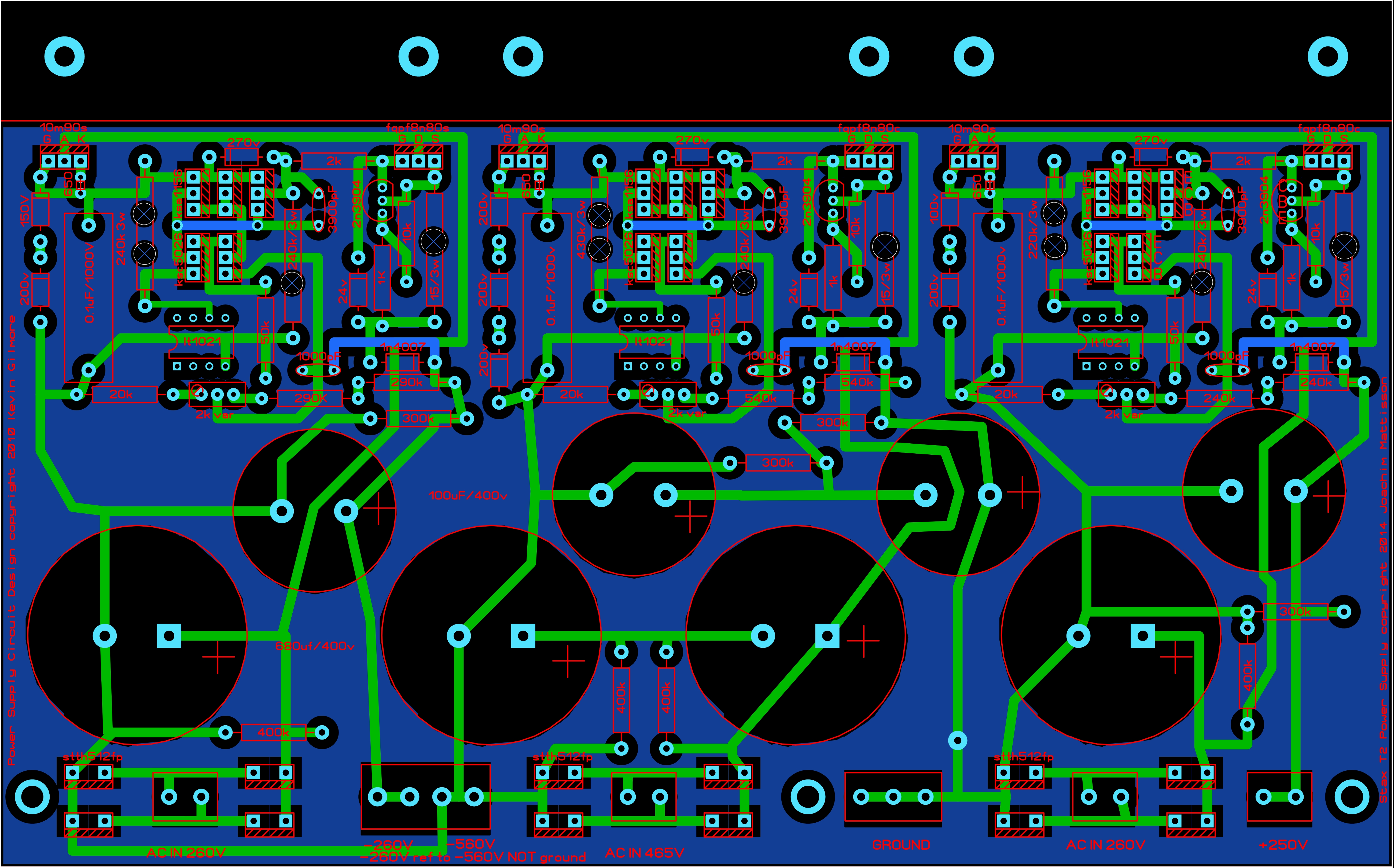
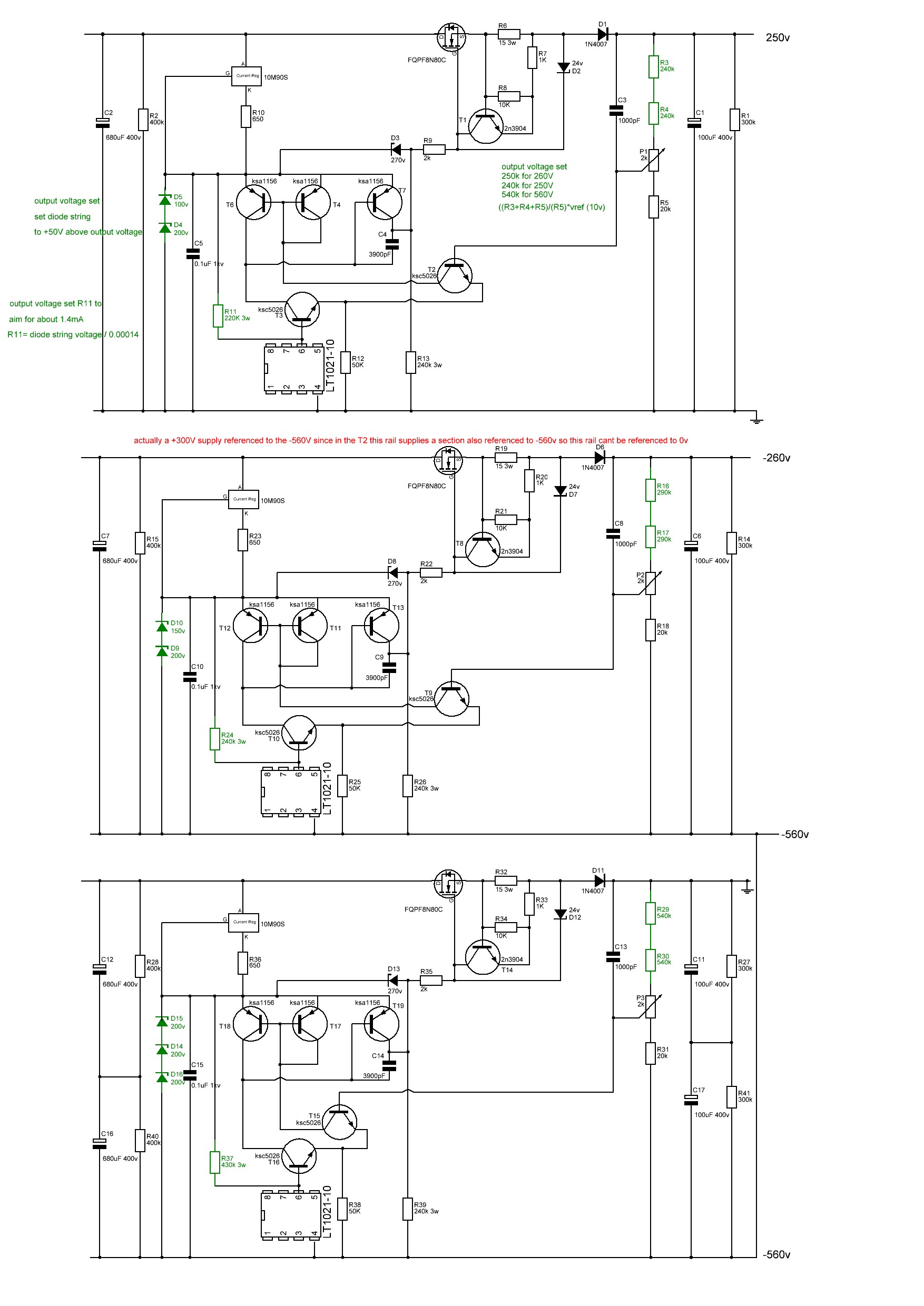
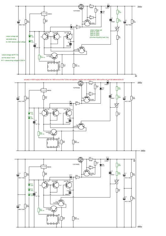
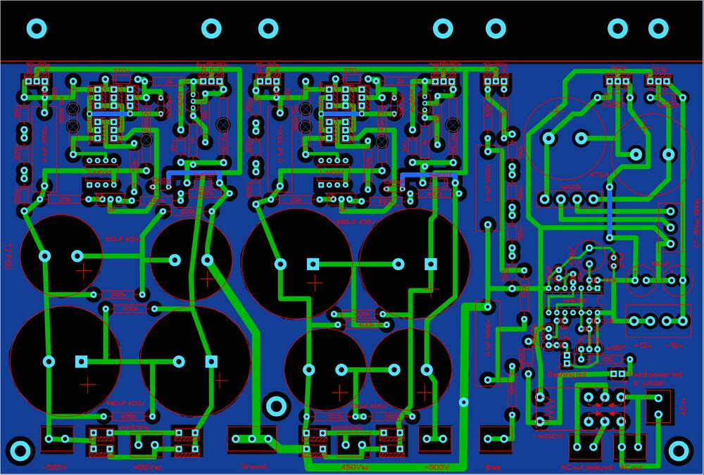
The original published gerbers has All the rails running at around 1.8mA through the R11 resistor except the +-500V rails at almost 2.3mA! The original published gerbers has: +250V rail (300V zenner string) using 160K so 1.875mA, 0.56W -260V rail (actually a +300V supply (with 350V zenner string) ) using 200K so 1.75mA, 0.61W -560V rail (600V zenner string) using 330K at 1.82mA, 1,09W +-500V rails (550V zenner string) using 240K almost double the required current at 2.29mA... and around 90C+ temperature with the lid off dissipating 1.26W... so if we set a target of around 1.4mA to provide a little headroom and go for values in the vishay PR03 resistor range available at mouser or radio spares: +250V rail 220K (available mouser and radio spares) for 1.36mA 0.41W -260V rail 240K (available mouser) for 1.46mA 0.51W or 270K (available radio spares) for 1.3mA 0.45W -560V rail 430K (available mouser) for 1.395mA 0.84W or 470K (available radio spares) for 1.28mA 0.77W +-500V rails 390K (available mouser and radio spares) for 1.41mA 0.78W... that's half a watt reduction in dissipation 🙂 compared to the original published gerbers. These lower dissipations might even allow the use of Vishay PR02 2W resistors instead of the 3W... time to update the gerbers and schematic again. I will update my gerbers and schematic post.
-
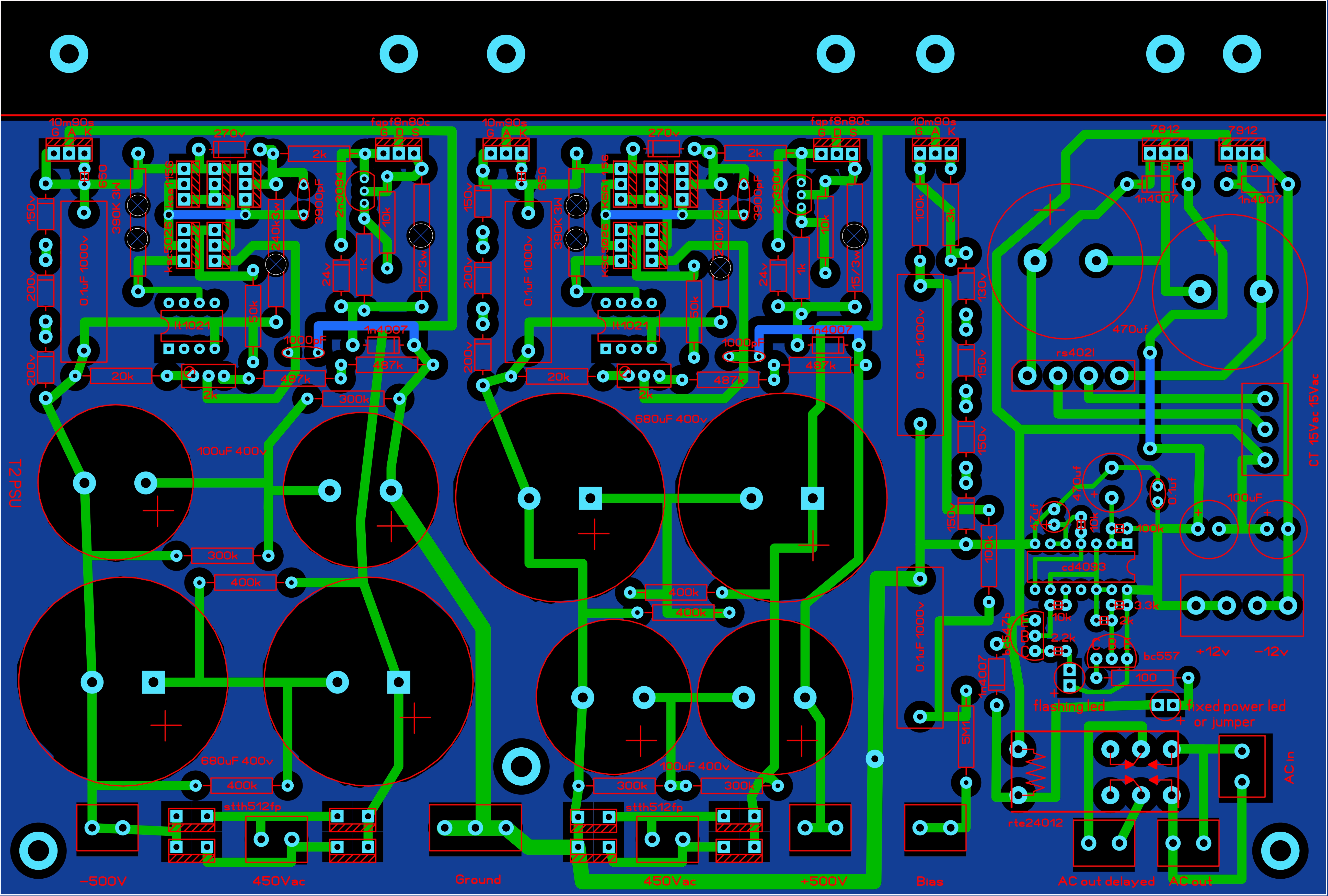
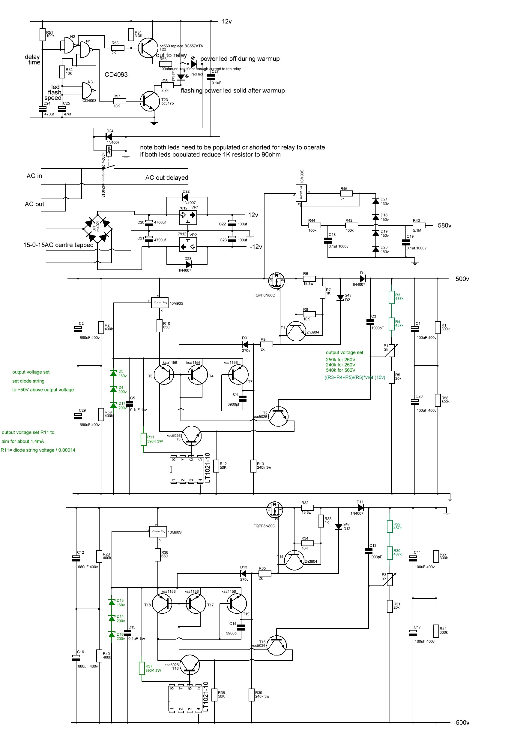
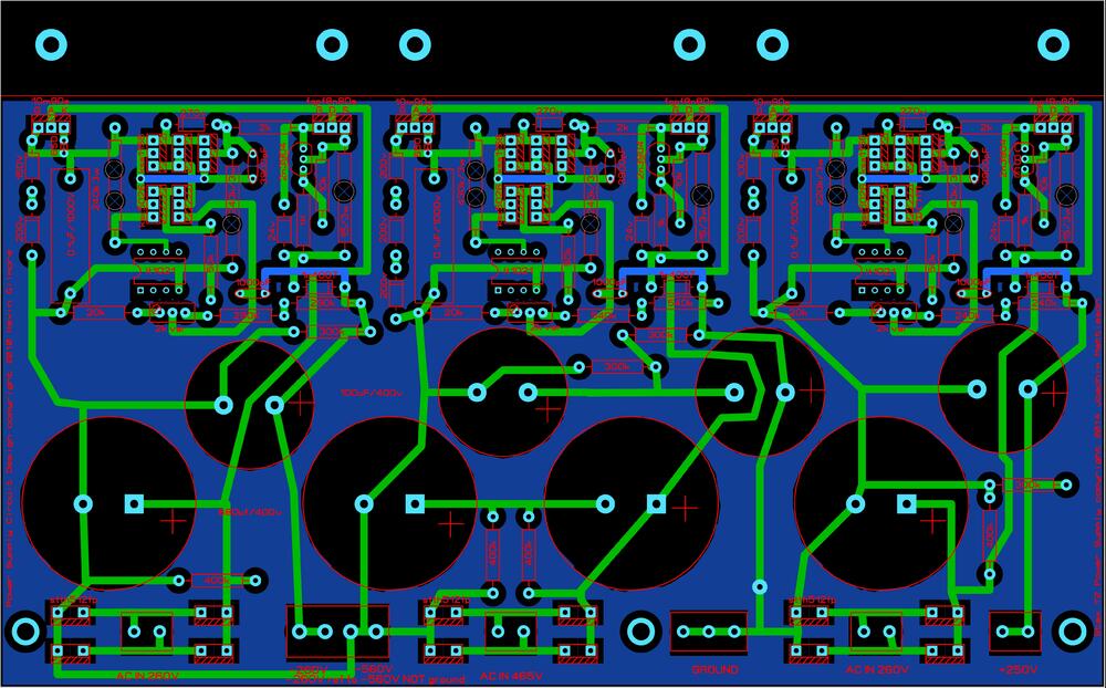
Here the latest T2 psus, I have modified the layout to provide more space around the rather hot R11 3W resistor and added vent holes to the pcb. The pcbs, transformers etc still fit inside a 400mm deep case without issue. I noticed that the R11 equivalent resistor on the + and - 500V rails runs considerably hotter than the equivalent resistor on the other rails (which also run quite hot).... doing some quick maths, R11 is approximately 1000ohms * the value of the zener serial train /1.818 on all the psus rails except for the +and -500V... Using this formula gives 300Kohms for the + and - 500V rails but in the original gerbers I worked from only have 240K there. This results in higher current flow through the resistor and more power dissipation and hence the higher temperature. EDIT: thank you Joamat for suggesting the current through R11 should be 1.1mA or more. The R11 values here on all rails are based around 1.4mA with values available in the PR03 Vishay range or 3W resistors. Resulting in lower power dissipation on all rails and especially the +-500V The gerbers with the vents have been used to make functioning psus and can be considered tested. This pcb is 220mm wide by 137mm deep and contains the -260V, -560V and +250V rails t2 kgsshv 250v -260v -560v corrected.zip ---------------------------------------------------------------------------------------------------------------- This pcb is 220mm wide by 148.5mm deep and contains the low voltage rails, delay and the +-500V rails with the adjusted 3W resistor t2 kgsshv +-500v, lv, bias and delay corrected.zip

-
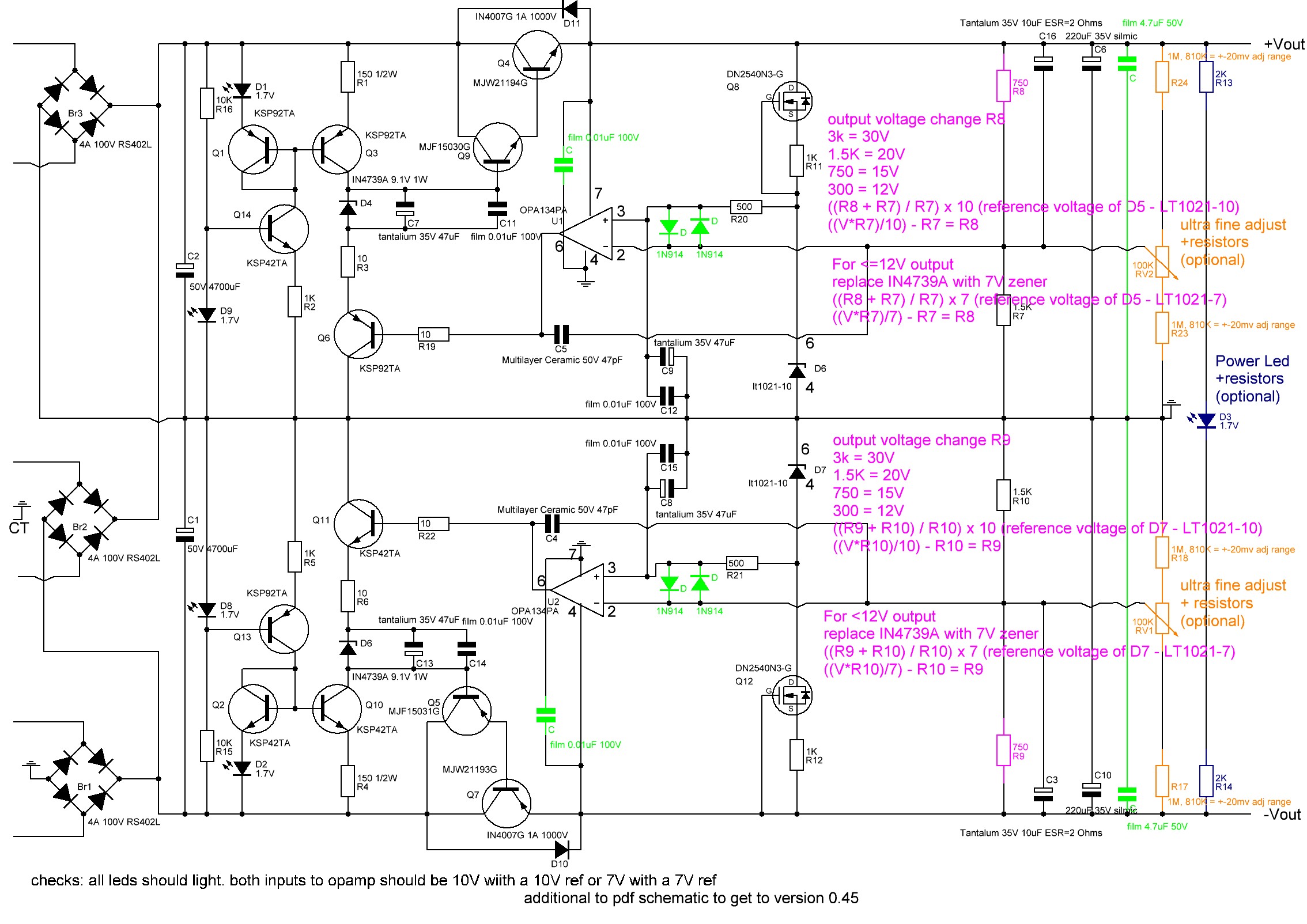
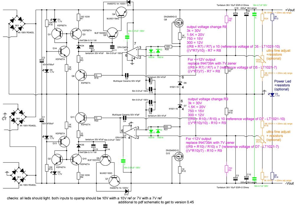
The output voltage is set by two resistors R8/R7 and R10/R9 (see schematic below). the trim pots make only very small adjustments - a few mV for those who want spot on voltages - there is a trade-off between adjustment range and temperature stability. If you want more adjustment range decrease the value of R24,R23,R18,R17. 810K instead of 1M for each gives about + and - 20mV adjustment range. If you want reasonably accurate voltages AND lower temperature drift you can use 0.1% resistors for R8,R7,R10 and R9 with low temperature coefficients (stock resistors are usually about 100ppm, 0.1% are usually around 25ppm) and omit the 1M ohm resistors and trim pot.
-
Simplified explanation: There are multiple methods for changing how a transistor or valve conducts. You can vary the voltage on valve grid or current on the transistor base. Another way is to vary the current supply to the transistor emitter, collector or valve anode or cathode, another way is to vary the voltage at the valve cathode. .. Just because the valve grid or transistor base does not have audio directly applied does not mean that there is no audio passing through the device.... Q1 is constant current. Since its emitter has a constant load and voltage applied and so has a constant current available and the base also has a fixed resistor and fixed voltage. Rv1 can adjust slightly the overall emitter resistance and therefore available current to each half of Q1 so some current balancing can be done to compensate for mismatches in the halves of V1 and V2 etc. The Q1 current is shared between the second 6922 (V2) (the one which does not have its grids connected to the audio input) and Q4/Q5. If second 6922 (V2) pulls more current then less current must be available to Q4 and Q5 since the total current available is constant and visa versa is true if the 6922 pulls less current. So the current through Q4/Q5 is effected by the current pull from second 6922 (V2) whos current draw is effected by the audio on the grid 1 of the input 6922 (V1) . Since the second 6922 (V2) supplies the anode current to the input 6922 (V1). if Q4/Q5 are effected by input 6922, Q11 and Q12 must also be since they get their current directly from Q4/Q5 and the base of Q11 and Q12 is held constant by the resistor string .. R36, R49,50,60 If Q11/Q12 have current draw effected by the audio input 6922 then the voltage drop across R11 and R12 and current through R11/12 must also be based on the audio input... since the current through R11 and R12 is directly controlled by the current through Q11 and Q12 The current through R11 and R12 control the current at the base of Q8 and Q9 and therefore control the current through Q8 and Q9. Q8 and Q9 control the voltage at the EL34 cathode and that's how the audio gets into the EL34s and that's the AC audio voltage than can be measured with an multimeter at the cathode of the EL34s.
-
-
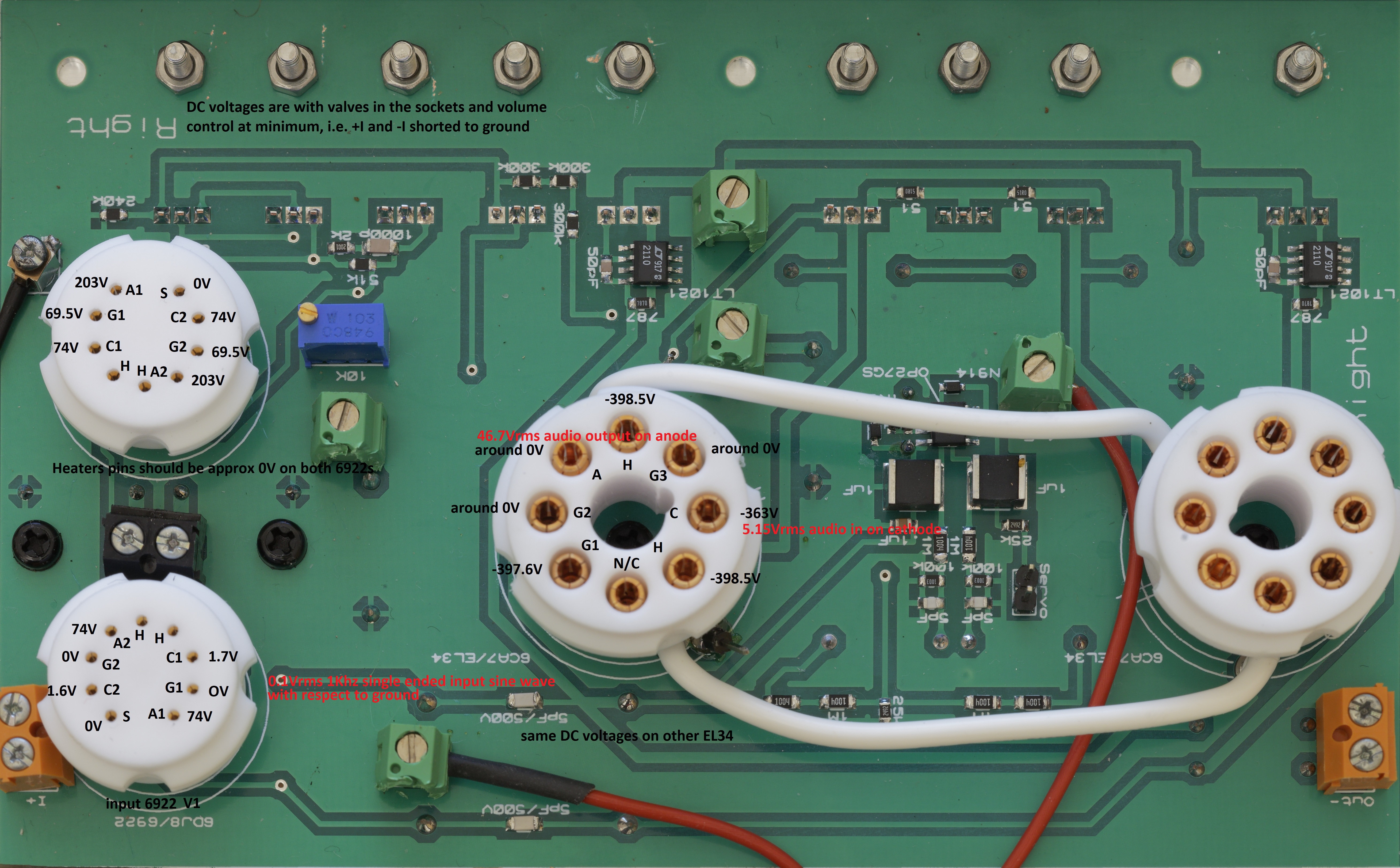
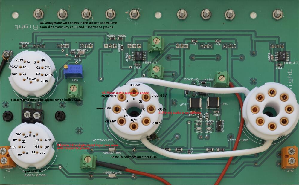
To help people with troubleshooting here are the valve DC operating points measured with respect to ground on a known good stock mini T2. Inputs are shorted to ground. No load on output. All components stock values and DC PSU voltage rails within 1% of schematic when under load. Obviously the two el34s should have identical DC operating points and so should each half of a 6922, the other channel should also match. Exact measured values are going to vary a bit depending upon the valves, exact PSU voltages component, tolerances etc etc. NOTE the EL34 heaters sit at approximately -400VDC. The 6922 heaters are approximately at 0VDC I get a signal gain of approximately 940x with a single ended 1Khz sine wave 0.1Vrms input and an output of 94Vrms between the + and - output pins into a 10Mohm (multimeter) load. Audio enters the EL34s on the cathode and for 0.1Vrms 1khz input I get approximately 5.17Vrms of audio on the cathode, the EL34 amplifies this by about 9 times and gives 46.7Vrms on the anode with respect to ground. The other EL34 operates similarly but opposite phase.
-
you need to consider the current flow.... audio goes into the grid of the input 6922 and the audio effects how much current the valve allows to flow from its anode to its cathode. The input valves anode current supply comes from the second 6922 cathode... therefore the current flow through the input 6922 effects the current flow through the second 6922... I guarantee to you (in a properly working min T2) the audio goes through the el34s... think about it.. how do we get 500Vrms audio output from a single 6922? A single 6922 can't do that kind of voltage swing.
-
i'm glad you are making progress. As originally designed the mini t2 should be able to output about 500Vrms with around 0.02% distortion with about a 0.5Vrms input. At 100Vrms output distortion should be about 0.004%.I think this is what you should be aiming for. I would also strongly advise that you build the golden reference HV power supply for the amp. Its an extremely high performance power supply and is the core of most of the headphones amps designs here. Its also all through hole and easy to build. It will also provide the 580VDC bias needed for the stax headphones.
-
-
-
the psu clearly has poor voltage regulation. The voltages have not all decreased by the same percentage but I don't think this is why you have almost no voltage amplification. if you connect the test signal to the + input and ground the - input do you get a similar output on both out + and out -? if you connect the test signal to the - input and ground the + input do you get a similar output on both out + and out -? how are the + and - 15V dc rails under load? (the -15v also acts as the input 6922 anode current sink) and what frequency is the oscillation when both + and - input are grounded?