jamesmking
High Rollers
-
Joined
-
Last visited
Everything posted by jamesmking
-
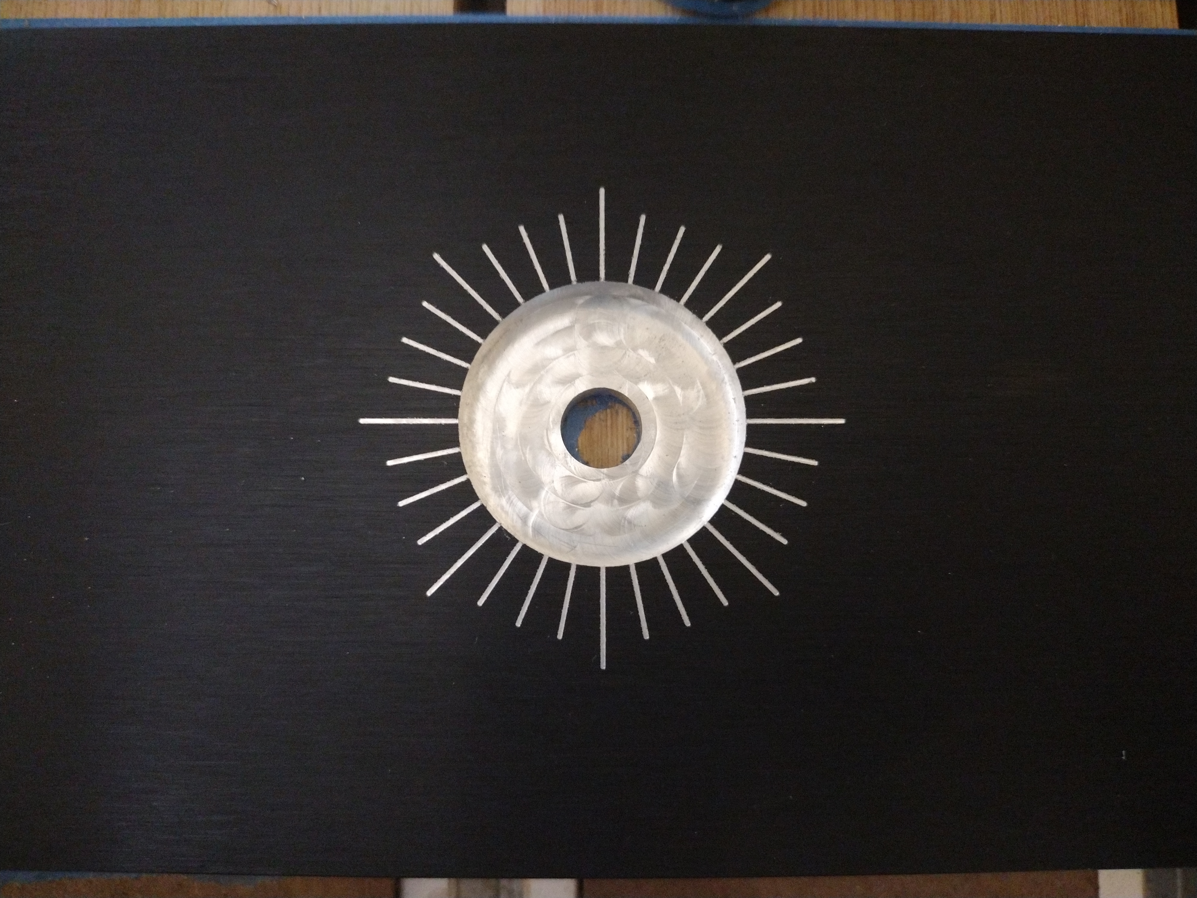
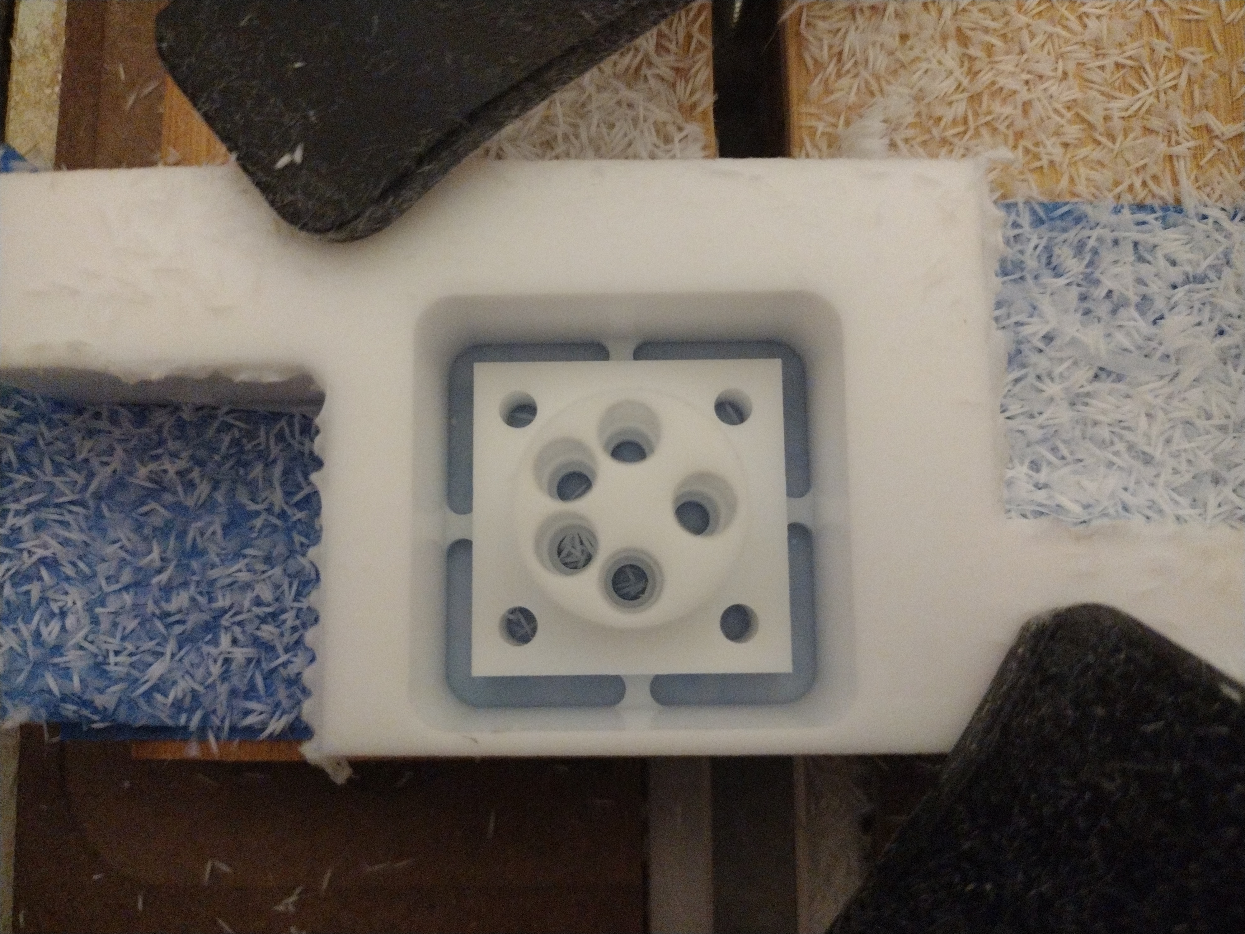
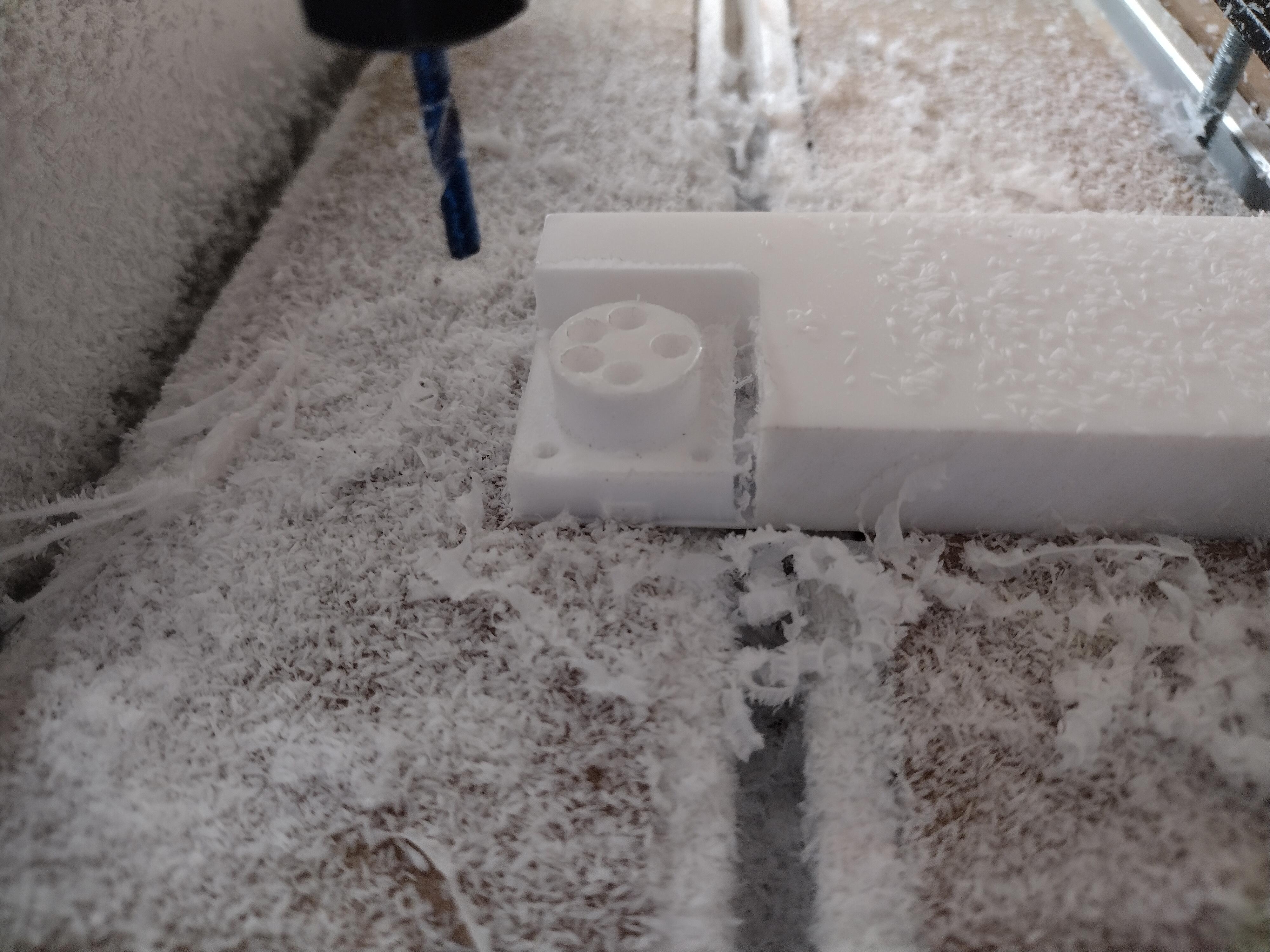
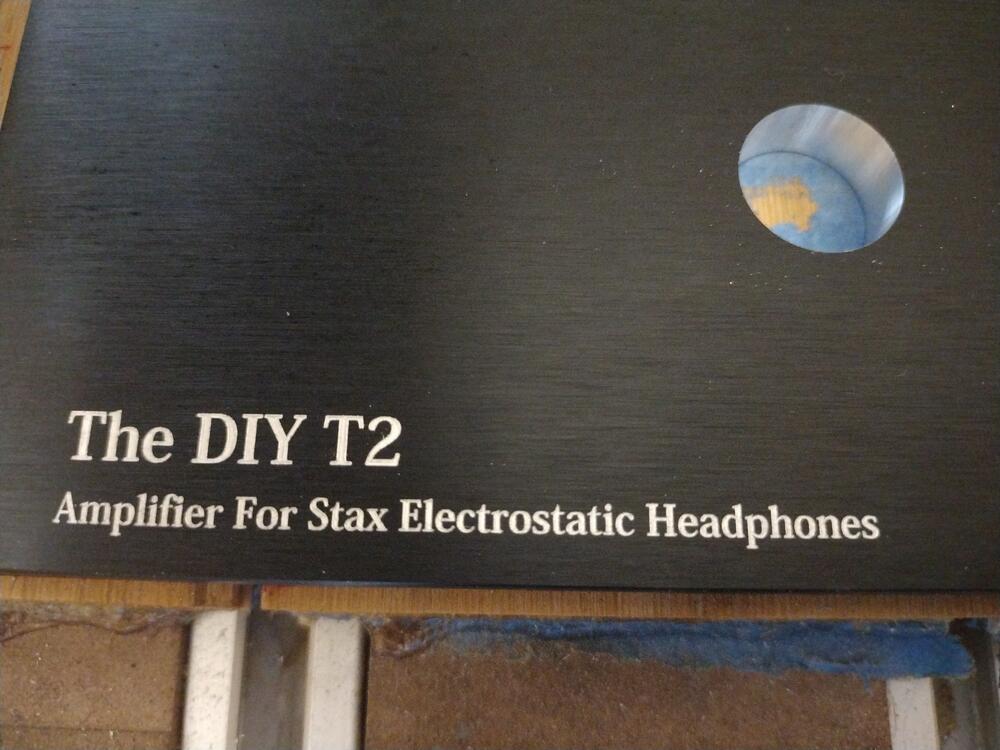
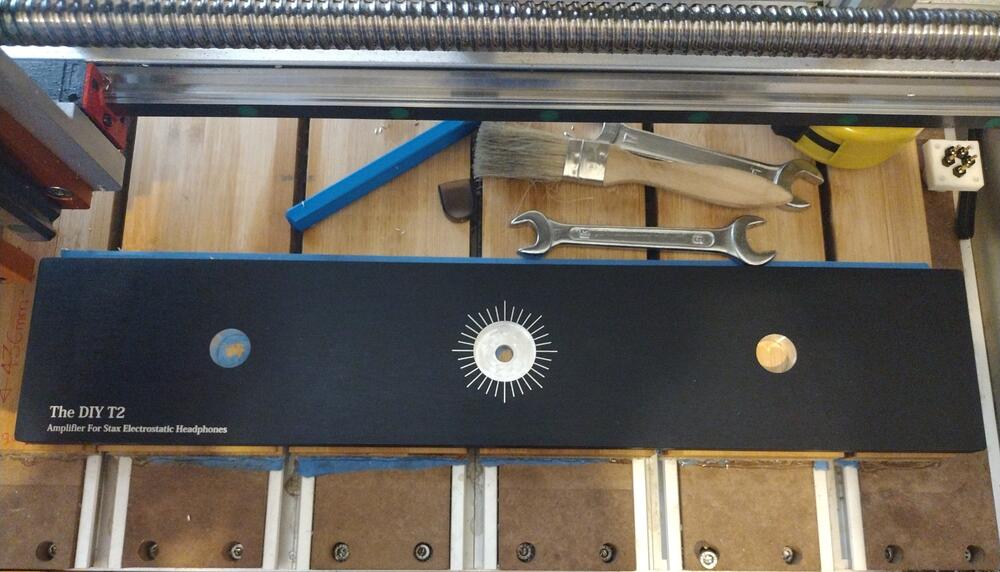
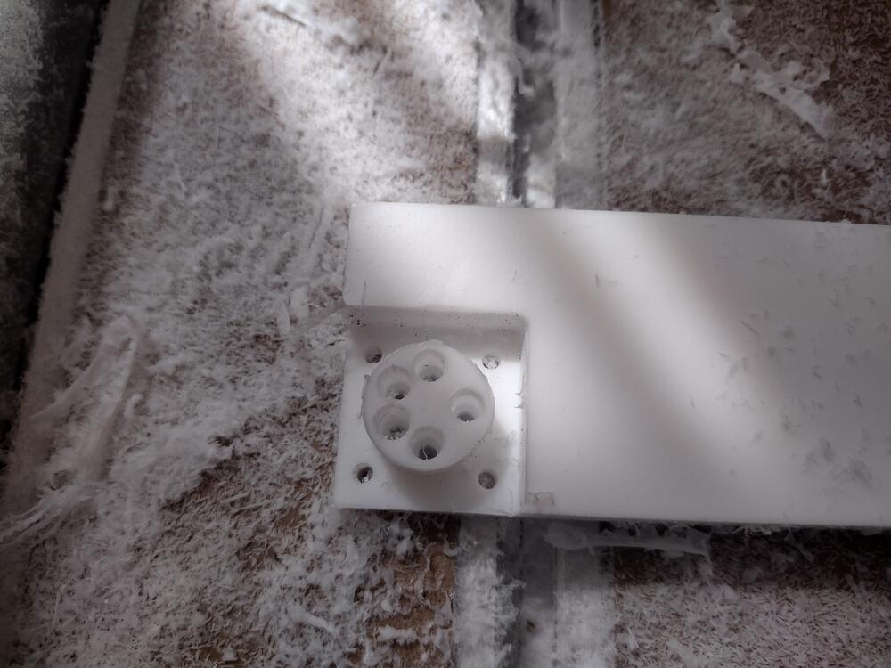
First attempt at a complete front panel. Single flute 6mm end mill and 0.1mm V bit used. Depth of cut 0.02mm on the engraving. I also used tape and CA glue as the hold down method for the first time - I really like it. Much less vibration and far quieter when cutting in the middle of the work piece compared to just clamping the corners. As usual no deburring or finishing pass. The surface finish on the volume pot pocket is silky smooth - the photo does not do it justice. Very happy with the results. Not so happy that I have zero artistic talent for cool looking front panel designs.... Another go at a Stax socket with the better quality end mills. Much better surface finish than my previous attempt cheapo mills and I'm using faster feeds and speeds this time. Just shows that a crap end mill gives inferior results even on soft plastics. There are no burs around the edges of the cuts and the surface is smooth.


-
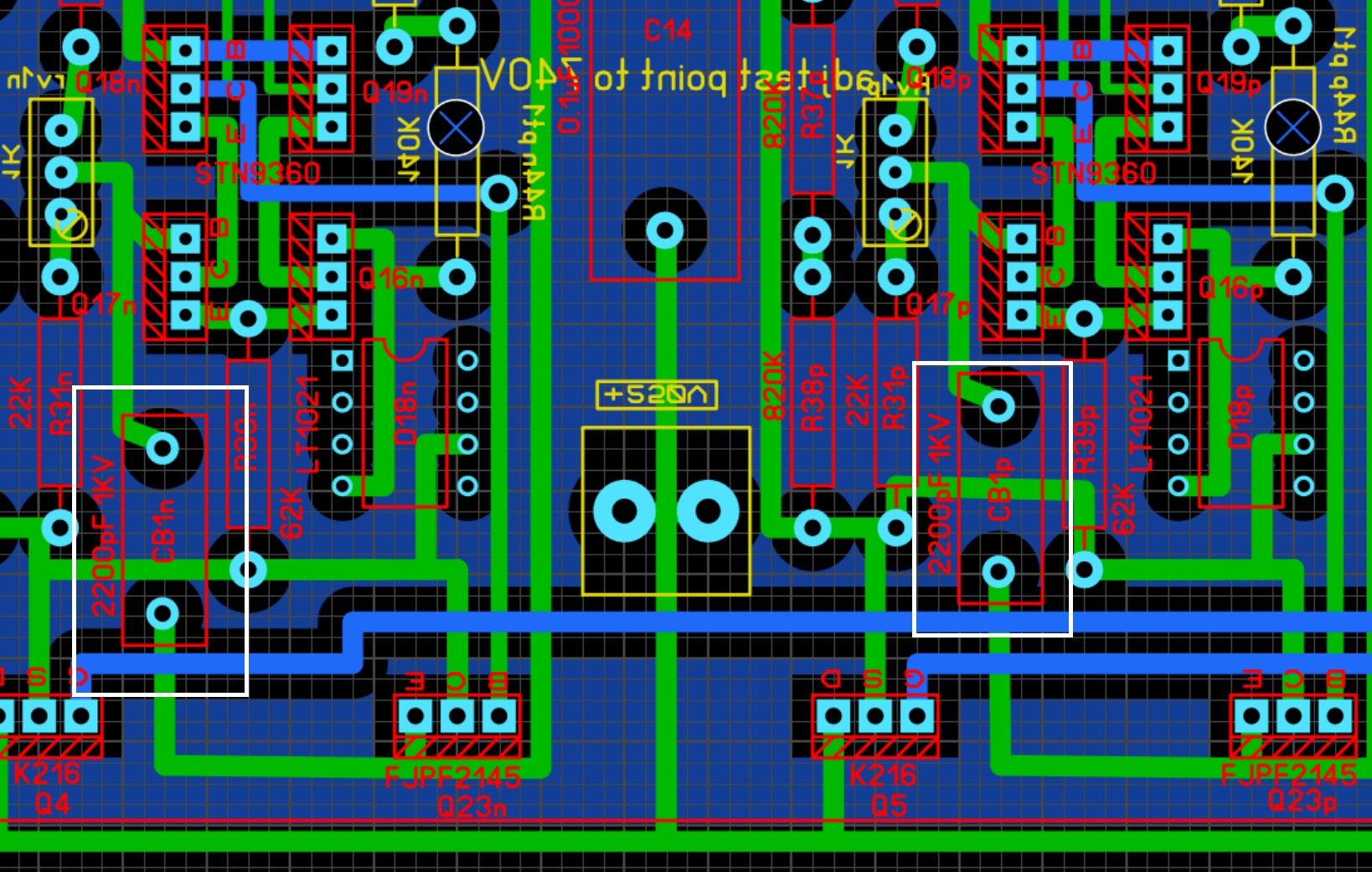
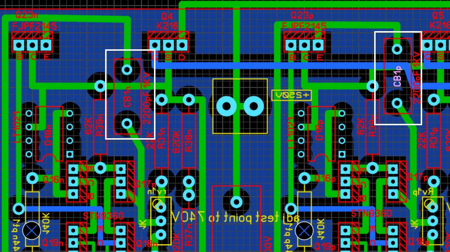
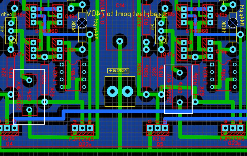
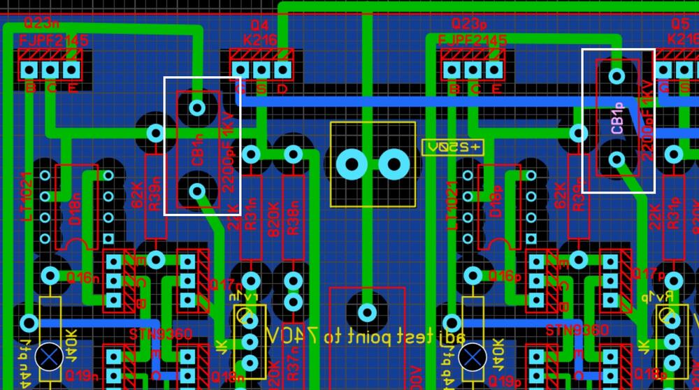
I would not want to speak for Joamat, but the impression I got was that the mini T2 was an attempt to simplify the complex design and make it as small as possible by going surface mount whenever possible. Ther is not a lot of space around Q17n but I think a 13mm by 4mm 1KV 2200pF (10mm lead spacing) film cap like a wima MKP1O112203C00JSSD will fit and there are film caps of the same size and rating ranging from 1000pF to 6800pF. The area around Q17p is more problematic due to an extra track which results in one tracking having to be rerouted. Channel 1: channel 2:
-
Nice work, its always good to see progress and new ideas for the T2. Just to clarify. I did not design the mostly modern T2 or its battery. I simply created a series of posts on my build and posted my modified gerbers and updated and clarified schematics. I have been trying to collate the information scattered over years and years of posts into one or two long posts to provide a detailed starting point for new builders. I would not want to take credit away from the people who actually did the hard work of designing and testing. Your battery looks promising. If I could suggest, PTFE caps of sufficient voltage are quite large and not easily available new. I think it would be possible to find a place on the amp pcb for 1KV film caps e.g. wima. I would also be interested in the effect on the existing mostly modern T2 battery if just the cap is fitted - since such a modification would be very cost effective for existing mostly modern T2s. If the cap mod is shown to be stable and reliable I would be happy to update my existing post to include it in the schematic as a option and update the gerbers to make a place for adding the cap. regards James P.S independently of your effort MLA and I think Joamat have been working on a variant of the mostly modern T2 amp board that replaces the unavailable new 79 and 216 transistors with tta004 and ttc004, which if they prove stable, could result in a T2 only using current production components. (the pinout of the tta/ttc is different to the originals but they have not so far had to make any other changes).
-
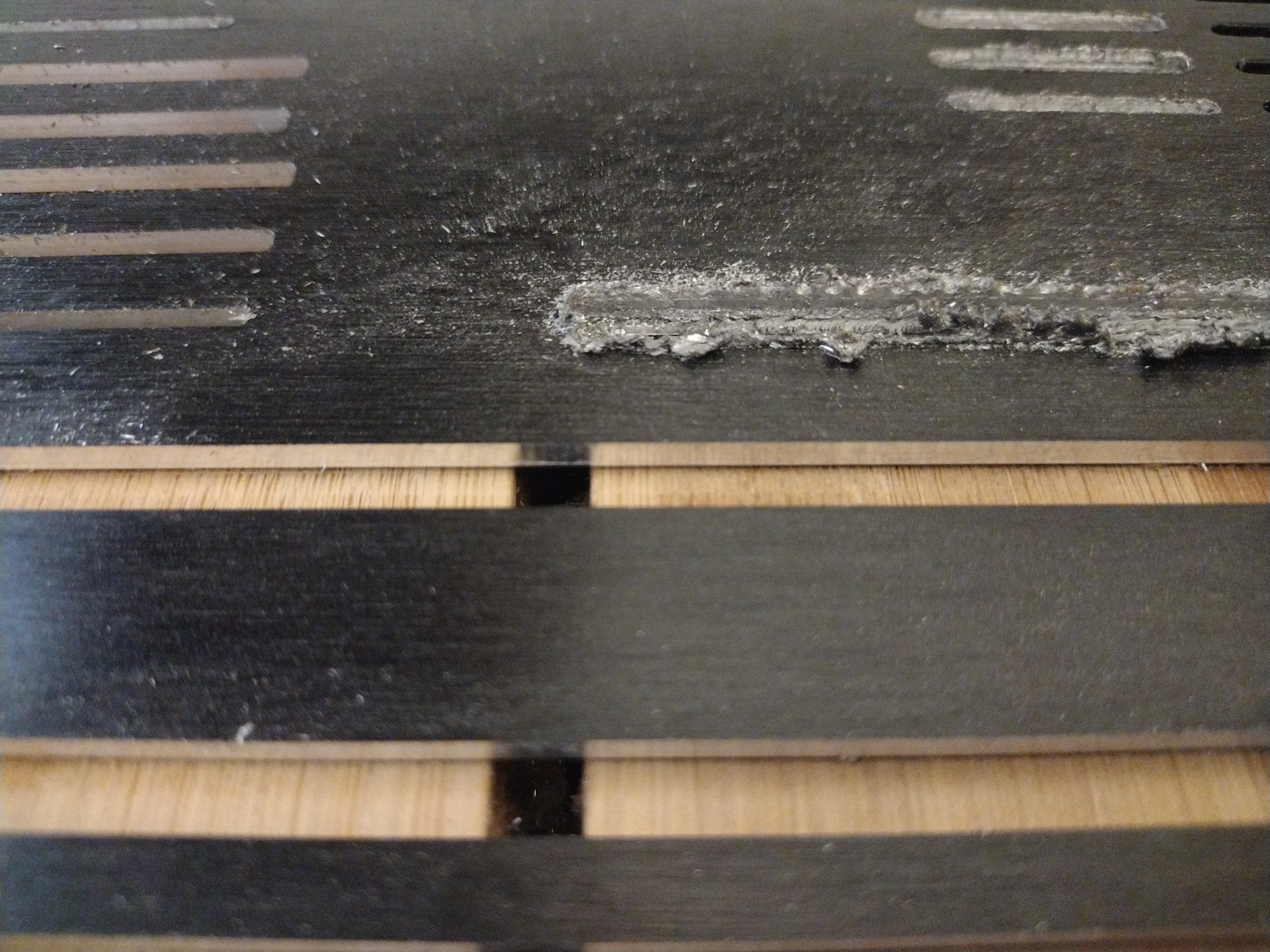
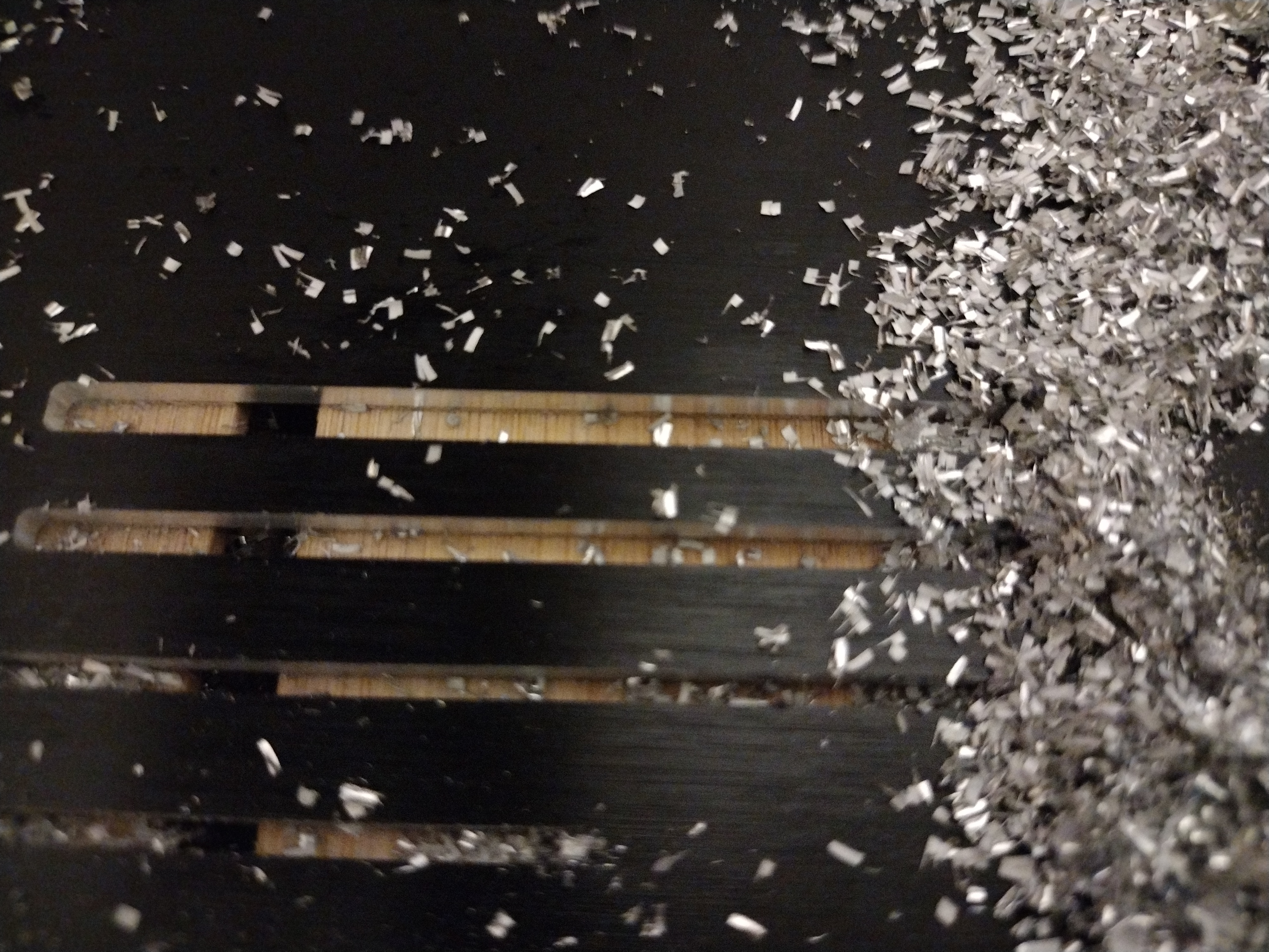
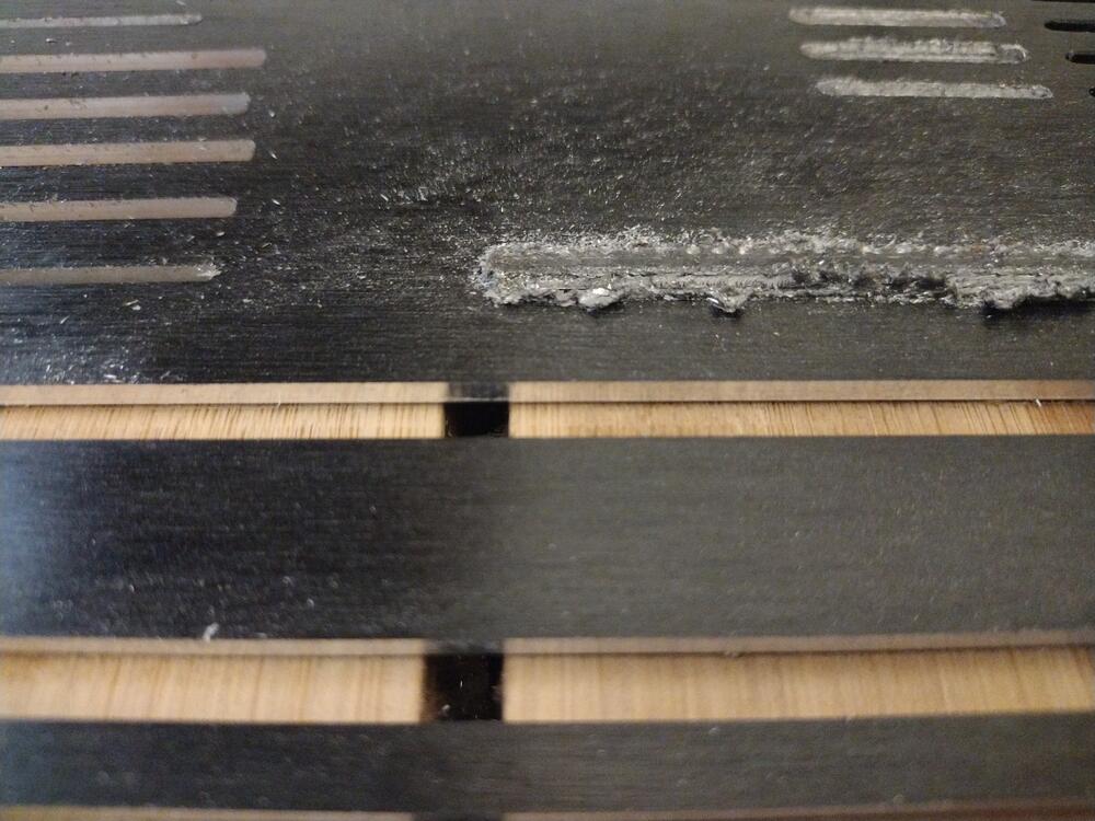
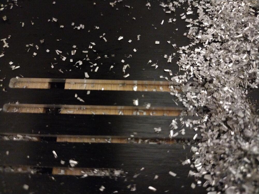
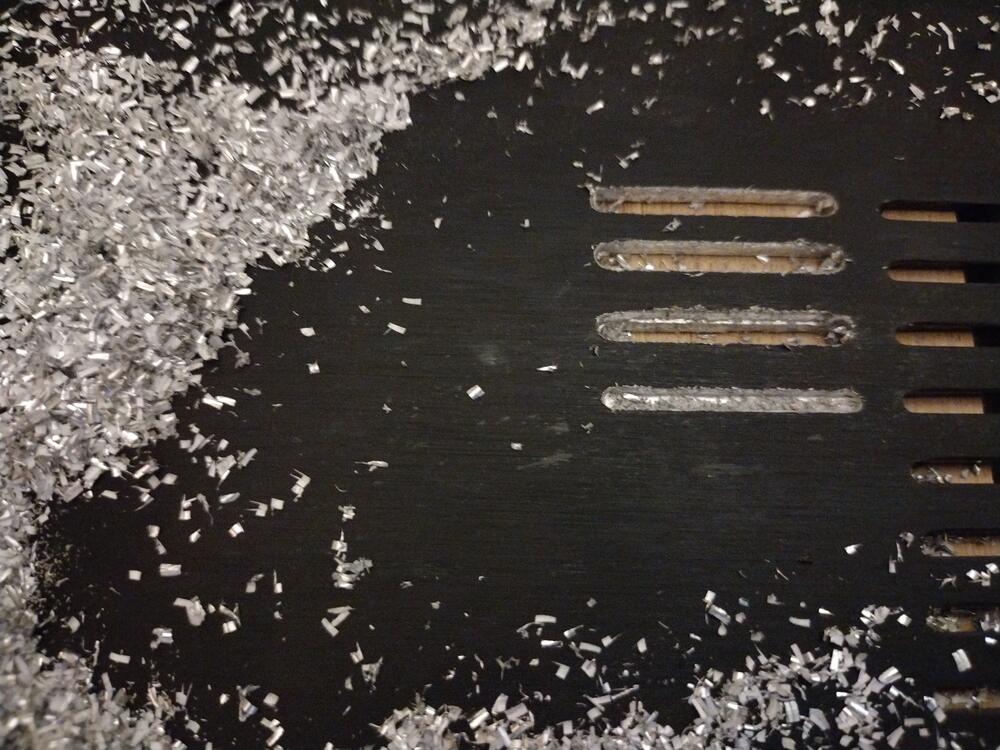
Things are looking up again... I just took delivery of some 6mm single flute DLC coated end mills, selling says they are designed to cut aluminium without liquid lubrication. Initial testing looks very good, absolutely throws chips out of the cut into near earth orbit when doing a full width slot. Zero chip welding. Surface finish as good if not slightly better than the 2mm end mill (So far got the speeds and feeds for the 6mm up to 400mm/min feed rate, 1.5mm DOC and 11K rpm). Cutting is very quiet and almost silent at 1mm DOC... The vfd and control box fans are louder than the cutting noises. I am sure there is much more to be got out of this end mill, but I'm progressing conservatively because these 6mm end mills are not cheap and I don't want to push it to destruction. The biggest take away for me is that buying cheap end mills from the manufacturer of the cncs website is not the best move and that end mill quality absolutely radically effects what you can do. I also think i'm going to invest in a oil/air mist system... (the hideous grey mess is the 3.175mm POC (piece of crap) end mill WITH cutting fluid dripped onto the cut... .) middle slot is 6mm end mill 1.5DOC 3mm total depth 11Krpm 400mm/min no cutting fluid no finishing pass no deburring... front slot same settings as middle slot but 1mm DOC and 10Krpm.
-
i have no idea of the type of aluminium, its a disapante case I purchased some time ago from modshop. The fact I got such good results with a 2mm end mill, especially on chip removal and surface finish on it makes me suspect the 3mm end mill is just crap (the 3mm comes from a different supplier and is a different brand to the 2mm). So I have ordered some 3mm end mills of the same brand as the 2mm. The spindle does not seem to be slowing down, vibration was low, cutting noise was low and I did not use any coolant with the 2mm... as far as I can see if I can go 300mm/min 1.6mm depth of cut on a 2mm end mill with zero issues, low cutting noise and no lubrication, (I managed to break it at 500mm/min 1.6mm DOC but I was deliberately seeing how fast I could go), I should be able to do similar with a 3mm end mill of similar geometry (both single flute and both DLC coated)... but the best result I got with the 3mm was 0.2mm DOC, poor top edge and much reduced rpm compared to the 2mm. Any time I tried to increase the rpm chip welding became worse and chip evacuation did not improve, any DOC above 0.2mm I got lots of vibration and nasty noises.... looking carefully at the cutting the 3mm was not pushing material up the flute instead material was wrapping itself around the outside of the cutter and then welding itself to the top edges of the slot. I did not seem to be cutting so much as ploughing. Slower feeds resulted in the chips becoming like power and welding themselves all over the cut like fur... I tried cutting oil with the 3mm and this did not stop the welding. Feeling the edge of the flutes the 2mm feels super sharp all the way up whereas the flute the 3mm only feels sharp right at the bottom tip of the flute and the rest of the flute all the way up does not feel more than moderately sharp. I suspect this is why I cant get any sort of depth of cut. Even plunge cuts at the beginning of the slotting sounded much nicer on the 2mm than the 3mm end mill. (plunges straight down at 25mm/min)
-
Short answer: in almost all cases high accuracy is not required unless specified otherwise in the bill of materials or schematic. Most builders are using 1% tolerance resistors up to about 1W, except in the most critical of uses, and high wattage resistors are usually 5% or so. Longer answer: There are several factors to consider. A "7K" 1% resistor could actually be between 7.07K and about 6.93K and still be in spec. Similarly 4.2K could be between about 4.24K and 4.16K and still be labelled as 4.2K 1% resistor. So if you are lucky with your 4.22K and 6.98K resistors they could fall within the specs of the 7K and 4.2K anyway. If you have a good LCR meter or multimeter you could buy multiple resistors, measure and hand select the closest match to the values you want. But this is usually not necessary and requires a highly accurate measuring device. If you need accuracy without measurement you can go for 0.1% parts but they cost more, typically don't come is as wide variety of wattages and often have lower voltage ratings. Also consider that all resistors heat up when current passes through them and the heat changes their resistance. The amount the resistance changes depends on the materials and manufacturing of the resistor and is usually specified in ppm per degree of temp rise (lower is better i.e. more stable but also more costly). Unless the use of the resistor in the circuit is critical, around 50 to 200ppm is fine for low wattage resistors and multiple hundred ppm is common for higher wattage... So in circuit, depending upon the power the resistor is dissipating, its resistance will vary from that measured when cold anyway... It is vital you don't exceed the voltage or wattage rating of a resistor and it is good practice to operate them bellow their ratings for safety and long term reliability. When looking at the voltage rating look for working voltage - this is the maximum voltage it can handle continuously. Some specs don't tell you working voltage but rather the maximum voltage just before failure which is a lot less useful. Some specs don't tell you if the voltage rating is maximum or working... so assume its maximum and the working voltage will be a lot lower.
-
Thank you Kerry, however, yesterday I then tried an uncoated 2 flute 2mm slotting endmill... the results was not good at all.... very poor chip evacuation and lots of chips welding to each other. Almost no chips get thrown clear of the cut. I'm not sure if the end mill is garbage or if something else is wrong.... I was looking online for some kind of guide that had photos of poor results and what to do about them... but there seems to be very little information other than feeds and speed calculators which seem to suggest parameters that I cant get close to. I tried to extrapolate settings from the great results I got from the single flute 2mm end mill to a single flute 3.175mm end mill but to no avail. The 3.175 end mill could not run at anywhere near the rpm or depth of cut of the 2mm end mill without welding, vibration and large burns on the edges of the cut.... Perhaps the 3.175mm end mill is just crap (its not the same brand as the 2mm)... wow cnc aluminium is frustrating...
-
I'm starting to get the feeds and speeds dialled in now I have a 1.5Kw water-cooled spindle and some good spoil board bed rigidity, properly levelled and trammed the machine. I'm slowly gaining confidence and beginning to believe the reviews that said the Vasto can cut aluminium... I managed to cut ventilation slots in aluminium using a 2mm diameter single flute DLC end mill with 300mm/min feed rate, depth of cut 1.6mm, 50% overlap, 18000rpm. The test slots were 160mm long, 3mm deep, I tried 2mm, 3mm and 4mm widths.... surface finish is like a mirror, no burs and no chips welding themselves to anything. No cutting fluid was used and there was no finishing pass: Thats so better than my first attempts with the 400W motor and a corn cob end mill which produced garbage surface finish at much lower surface speeds, much lower depth of cut and destroyed the end mill very quickly:
-
I entirely agree, for me the object of listening to music is emotional involvement and enjoyment. The combination of the mostly modern T2 and the SR007 does this for me in a way nothing else I have listened to can. It makes music rather than throwing detail and frequencies at you. I don't care if its not as "accurate" as something else or technically or measurably not as good. I know of no measurement or technical specification that correlates with enjoyment or musicality. I think the general trend in hifi has been for things to get brighter and brighter in the search for more "resolution" and "speed" and more "high end" sound, hence the trends for metal drivers, more silver plated/solid silver things like wires/fuses caps etc etc. If you like brighter then the sr007 is not for you, if you don't like modern sound then the sr007 can be wonderful - if driven properly and the standard stax energizers can't drive it property at all.
-
my solution to have solid brick between me and the laser. I run the laser in one room with the room door closed and control/monitor it from the adjoining room using a cheap web camera. I don't put any faith in it or the goggles that came with the laser....
-
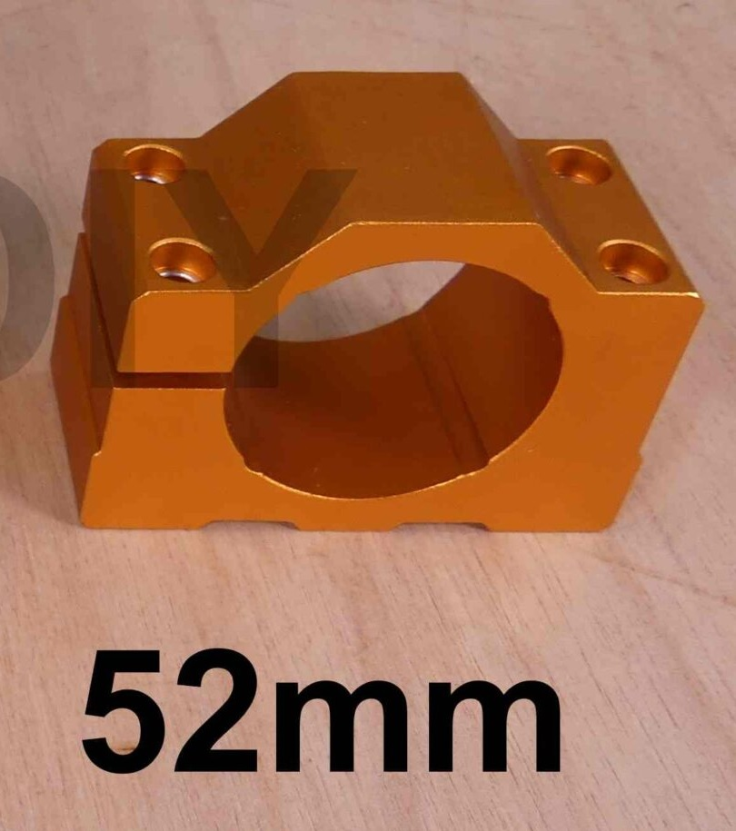
the diode lasers tend to come in rectangular aluminium blocks which have fins and act as heatsinks with a fan blowing downwards through the heatsink and a small controller on the top. The standard 400W spindle mount on my machine has 4 small notches in it so it can also mount the laser just by holding on to the corners. You don't need a high clamping force. So you could probably 3d print something if necessary. The hole is 52mm diameter. If you are planning to engrave or cut wood then additional air flow is recommended to clear the smoke (which would otherwise scatter the laser light) for aluminium engraving there seems to be no smoke. wow that spindle with quick change costs more than my entire cnc machine with the upgrades I have done so far.... My vfd and spindle is cheap chinesium, the only issues going that route is that there is a general lack of documentation and the seller could not help so i had to guess, experiment and look at you tube videos of similar setups for the vfd settings etc to get things to work. The vfd did come with a manual which was mostly understandable but although I purchased the spindle and vfd as a bundle the spindle had zero documentation and no information on how to set it up the vfd for it... the seller could not even tell me the diameter of the tubing required to fit the compression fittings on the spindle for the water cooling... so I had to guess and fortunately got it right first time. I also had to guess how many poles the motor had and use a tachometer to verify.... So if you are going chinesium I would ask the seller some questions about the tube diameters, motor poles, vfd settings etc and see if they have a clue before purchasing from them... Also I have found a general lack of attention to detail going chinesium, for example the vfd has three terminals marked earth. Two are totally isolated from everything including each other. Only one actually connects to the earth pin of the mains plug and the spindle takes a 4 pin plug, 3 for the power phases and you would assume the 4th pin is to ground the spindle body, nope no continuity to the body. Also on the vfd it has a temperature readout for the driver mostfets... always says 0C googling says this is normal temp never implemented....

-
i have the foxalien 20W which is a single diode with 5W actual optical output. https://www.foxalien.com/en-gb/collections/cnc-accessories/products/foxalien-20w-fixed-focus-blue-laser-module-kit fox alien also sell a 40W which is dual diode and about 10W optical output. You need a cnc controller which has a laser output. The fox alien is 3 pin - 0V dc power ( I think 12 or 24V) and a pwm for laser power control. Im using lightburn software which works well and has some laser test and calibration templates built in. General consensus on the internet seems to be that if you run a diode laser at full output you wear out the diode very quickly. So im tending to go slower movement and lowish power. The cnc controller board takes the spindle speed control commands and converts them to pwm signals for the laser output power control. On the fox alien vasto this requires setting a slide switch on the back of the controller to laser mode AND sending a G code command to go into laser mode. The slide switch disables the 48VDC motor output via a relay, disables rpm control via the speed potentiometer and enables the 3 pin laser output. The g code command tells the cnc controller to convert g code rpm commands to a pwm laser power control signal. I have also changed the stock 400W 48VDC air cooled spindle for a 65mm diameter er11 1.5Kw water cooled and a vfd. I would have preferred 80mm diameter er16 as suggested in this thread but I don't have an 80mm mounting bracket and the Z axis of my cnc does not look like it will take a bracket for 80mm spindles. Initial results are promising compared to the 400W. I still need to tweak the vfd settings for accel, breaking and torque. The stock spindle is cheap and nasty. I took it apart and it has two small bearings and the case is thin and the entire thing is held together with two long bolts. Its not very rigid at all and certainly seems to be one of the weaknesses of the machine along with the spoil board.. The 1.5Kw feels far more rigid and is 3 phase 220VAC.
-
normally if you go from 120V to 240V you half the current draw power = current * voltage so you may have a problem. Assuming the amp did not blow fuses when set to 120V the same value fuse should not blow at 240V... fuses can weaken over time and they do vary considerably. EEV blog on you tube did some interesting experiments and found the fuses ratings to be at best a guestimate. With large variations in the fail current for fuses from the same batch. There are multiple versions of the DIY T2 and the choice of valves effects power consumption a little. My T2 consumes about 205W once warmed up (mostly modern T2 with tung-sol el34 and genalex 6922, kghssv psu). there is a high voltage delay built in to allow the tubes some warm up before applying high voltages. When the high voltage psu switches on it initially has to fill the filter caps and this makes short duration current surge of more than 4A. Assuming there is no short circuit in your high voltage rails and you have not wired up your transformer incorrectly, its this initial charge that's blown your fuse. I am currently running 5A slow and that been fine for many months. 4A slow blow might be ok too. Having said that I always specify my transformers with resettable thermal fuses built in for a bit of extra protection.
-
The 12900k is very good at single threaded performance, multi threaded is good BUT its value for money is poor and the motherboards are not cheap.... yes you get newer versions of pcie but apart from a few expensive M.2 ssds nothing really takes advantage of the new pcie. the 12xxx series have performance cores and non performance cores and it makes the operating systems task scheduler much more complex because it now has to decide which tasks should go on the high performance cores vs which go on the lower performance cores.... and the new scheduler is only available in windows 11, so if you stick with 10 you potentially can lose some performance 12xxx series support both ddr5 ram and ddr4 but not at the same time (so your choice or ram and motherboard are tied together) ddr5 ram is almost twice the price of ddr4 for perhaps a 10% performance up lift... also most 12xxx motherboards don't have a lot of sata connections so if you have lots of physical drives you may have issues and require an additional sata or HBA expansion card... all in all 12xxx is a hot running expensive platform, slowly dropping sata support for more and more m.2 drives.. so if you don't need the horsepower stick with what you have. I would also mention AMD as a more cost effective option BUT: The only "modern" system I have is an amd 5900x and I would hessite to recommend it because of hardware and driver bugs that have persisted for years. I tried raid, stuttering, drives completely dropping out and only reappearing on reboot, terrible performance unless I loaded down one core... then it just worked... I guess it was power save and frequency scaling bugs. As soon as all the cores dropped bellow 3.6ghz drives vanished or hung. I ended up having to go non-raid. AMDs non raid drivers where SO bad AMD dropped the drivers and just provide Microsofts' ancient standard sata drivers with no chipset specific optimisations. After this I still got occasional random stuttering and random short duration windows freezes... turns out the amd equivalent of TPM (trusted platform) had bugs. I was using it for boot drive encryption... That bug was present from the beginning and only got fixed a month ago. After they fixed it they admitted there was a problem if they had admitted earlier I would have tried an add on TPM rather then the in built one but I had no way of knowing what was causing the freezes. Then I got audio issues, random stuttering unless I loaded down one core. Paradoxically increasing the soundcards hardware buffer (which should have reduced the stuttering actually increased it).. I ended up using tiny hardware buffers. Timing errors, dma or interrupt issues I guess. Same soundcard worked flawlessly on multiple intel platforms. Before all of these issues there was widespread well documented issues with usb randomly dropping out... but I purchased after that got fixed so I did not experience it myself. I was very happy with the cpu performance and value for money but the overall experience was not at all polished amd left a sour taste in my mouth. My 5900x experience was the most frustrating of any build I have done over the last 20 years and the lack of timely updates and acknowledgments of issues from AMD did not help... My experience with Intel is it just seemed to work. Now with the latest fixes from AMD things are not bad but I don't have confidence another driver or hardware related issue with not magically appear and take multiple years to fix... I just cant trust the platform in the way I can with intel. Oh and I almost forgot to mention 13 gen intel is around the corner... it will only be an incremental upgrade since it will be a refinement of 12 gen but that might explain why the seller is pushing hard for you to upgrade - so they can shift stock before it gets obsoleted in a few months. Unless you want the features of 12 gen intel stick with what you have and save a ton of cash for DIY builds or music. Long gone are the days of upgrading from say a 286dx 12Mhz to a 386dx 40Mhz and seeing a 2-3x performance uplift in a single cpu generation... now its more like 25% increase in 4 generations. Yes you get more cores in each generation but very little software will exploit all the cores so unless you are doing coin mining, massively parallel video rendering etc most of the cores will just sleep...
-
mono has a multitude of advantages over stereo, both in terms of economics and practicality: mono is more "pure" than stereo. for sessions recorded on tape full width mono had better signal to noise ratio than half track stereo. you have more control over speaker placement, you get no cross talk, you can buy better sounding mono components for the same money as the stereo equivalents, your interconnect and speaker cable costs are halved as is the cable clutter almost all recordings before about 1958 are mono anyway, you can store twice as much music on your harddisk/ssd as stereo, stereo recordings often had mono mixes - because at the introduction of stereo many studios where unsure of if stereo would be popular due to its higher cost, and of course, had much more experience recording with mono. Many of the mono mixes are better regarded and more sought after than the stereo mixes from the same sessions. e.g. the Beatles... (https://www.chicagotribune.com/opinion/editorials/ct-beatles-mono-mixes-lennon-edit-20141003-story.html) do you critically listen and prefer music in 7.1 surround sound? no why because its artificial, complex and detracts from the music, its a gimmick.. then why listen in stereo,? Apply Occam's razor reduce to the simplest form use the original and best form... mono... mono ©️ the way it was meant to be played ... 🙂
-
C2M1000170D has just become available again from radio spares. if you want to avoid mouser (currently out of stock anyway) or digikeys current pricing gouging of $9+ EACH. In radio spares select production pack not standard pack to see 1213 in stock minimum purchase 5 the price is still more than pre-silicon shortage levels but is low compared to other sellers.
-
unfortunately now mouser, farnell and digikey now have the FQPF8N80C as obsolete and no longer manufactured...
-
0. lose your conscience 1. get an oem to make the thing for you (cheap as possible no need for quality/performance) 2. attach pointless bling to the oem thing (if you are out of ideas for bling try a university art department, get the students to do it as a project for zero cost. Offer the students a 10% discount on the final product as an incentive) 3. get a e commerce web site (students studying computer science should be able to make it for you again offer 10% discount) 4. bribe some reviewers (give them the product so they can give it to their mistresses) 5. get lots of media exposure (talk BS about your innovative product) 6. create a cult following (amongst the rich and famous. limited editions, special one offs etc) 7. sit back and watch the money roll in.... (get a swiss or caiman islands bank account) 8. get a good accountant and avoid all taxes 9. get your product ridiculed on head-case (who cares your are now a millionaire) 10. go back to step 1 when sales of your current product start to drop 11. if income still falls make a NFT version 12 if NTF does not make enough money invest in bit coin, lose all you money and go back to step 1 I hope this plan is detailed enough for you.... 🙂
-
I'm tempted, it must be decades since I went to a hifi show of any sort. But I'm not sure of the point i am very happy with my mostly modern t2 and sr007 combination....
-
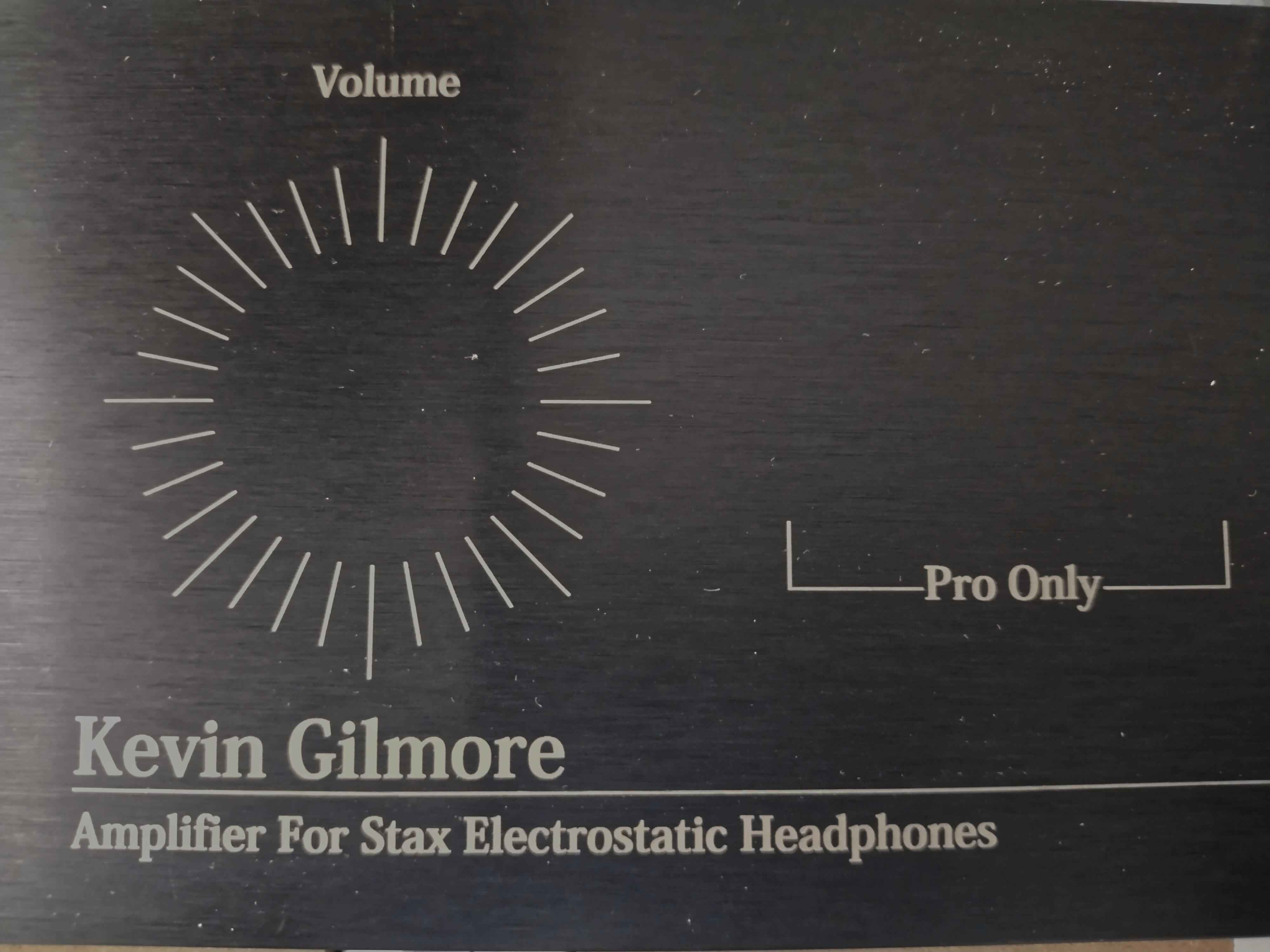
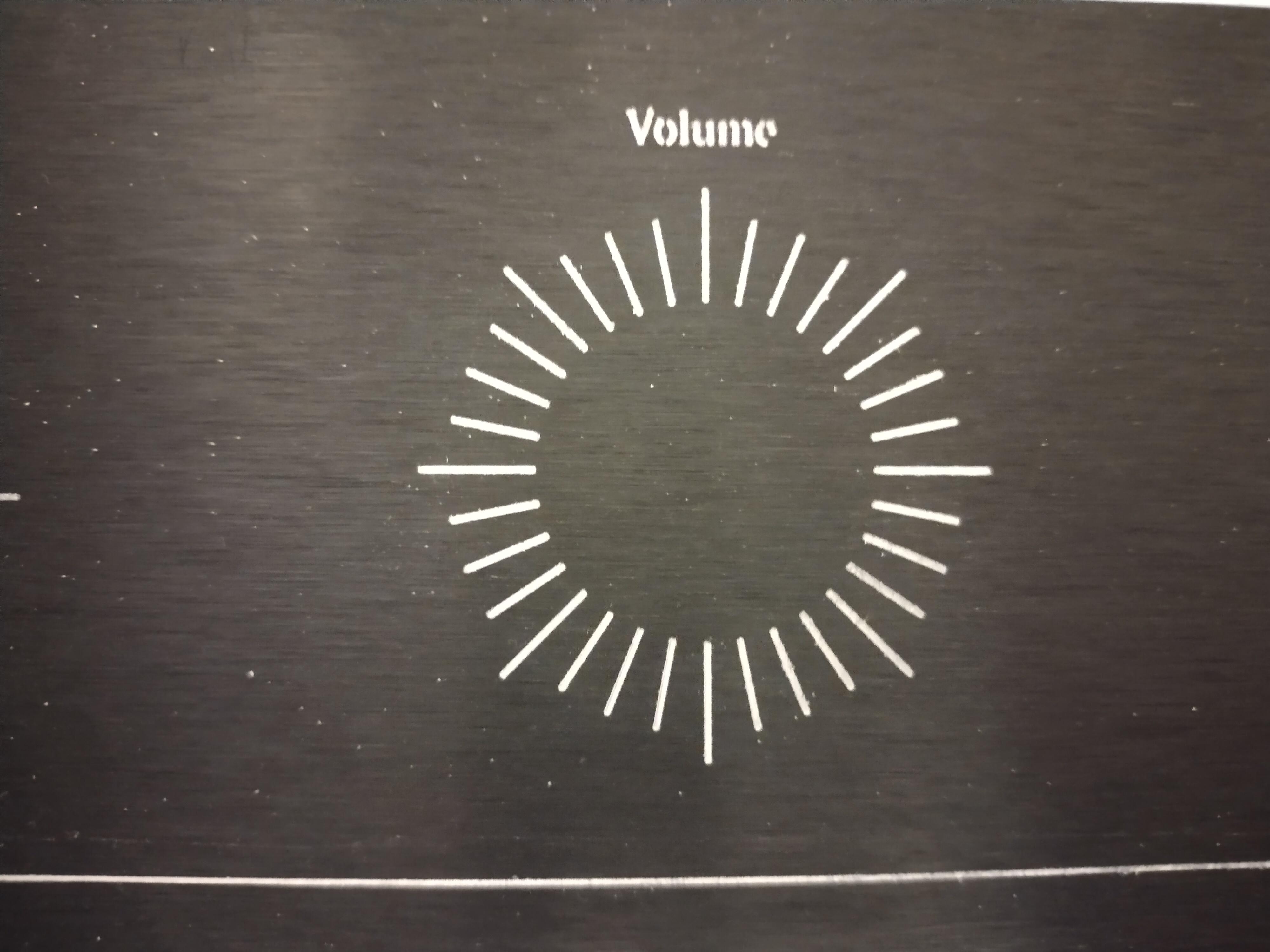
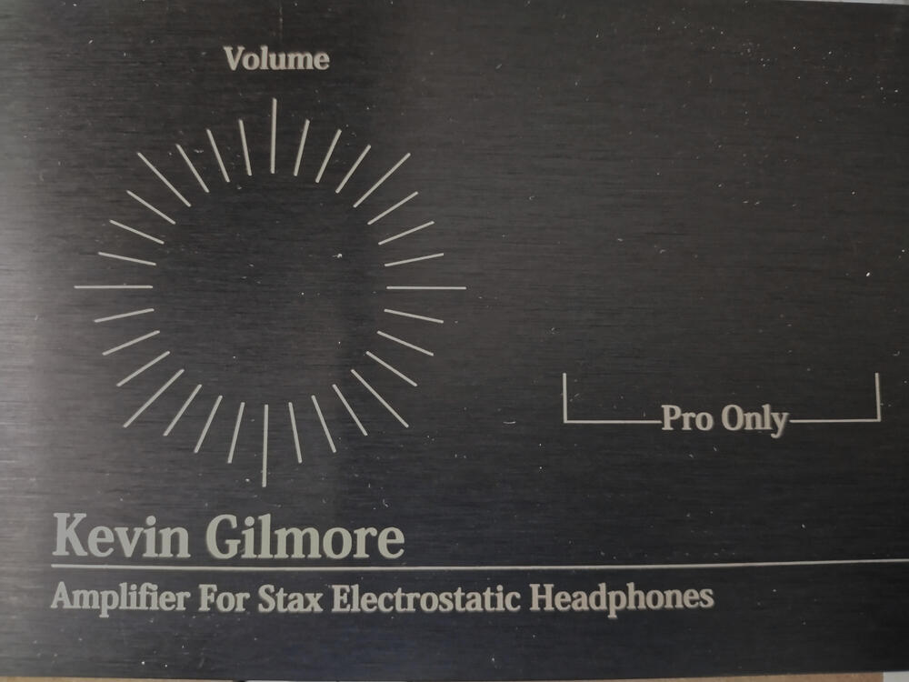
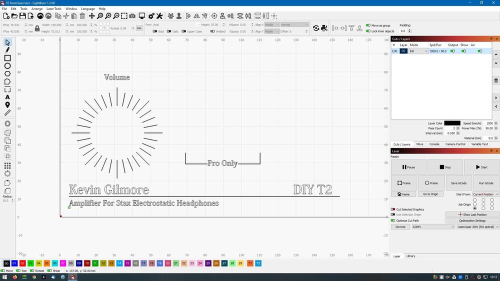
well the missing bolts arrived and the free 20W laser... so I had some fun trying to burn front panel markings. After a few experiments I realised the default settings in light burn are insane...6000mm/min movement speed no way! and 0.1mm between steps does not provide good resolution and gives a streak effect on text and slightly jagged lines... I improved by changing the settings to two passes at 90% power, 0.05mm stepover and 1000mm/min. This gives a crisp result (crisper than my camera phone can show). The result is not a shiny as engraving with an actual 10degree 0.1mm engraving tool, so I will experiment a bit more. I guess I am still not quite getting all the way through the anodizing.
-
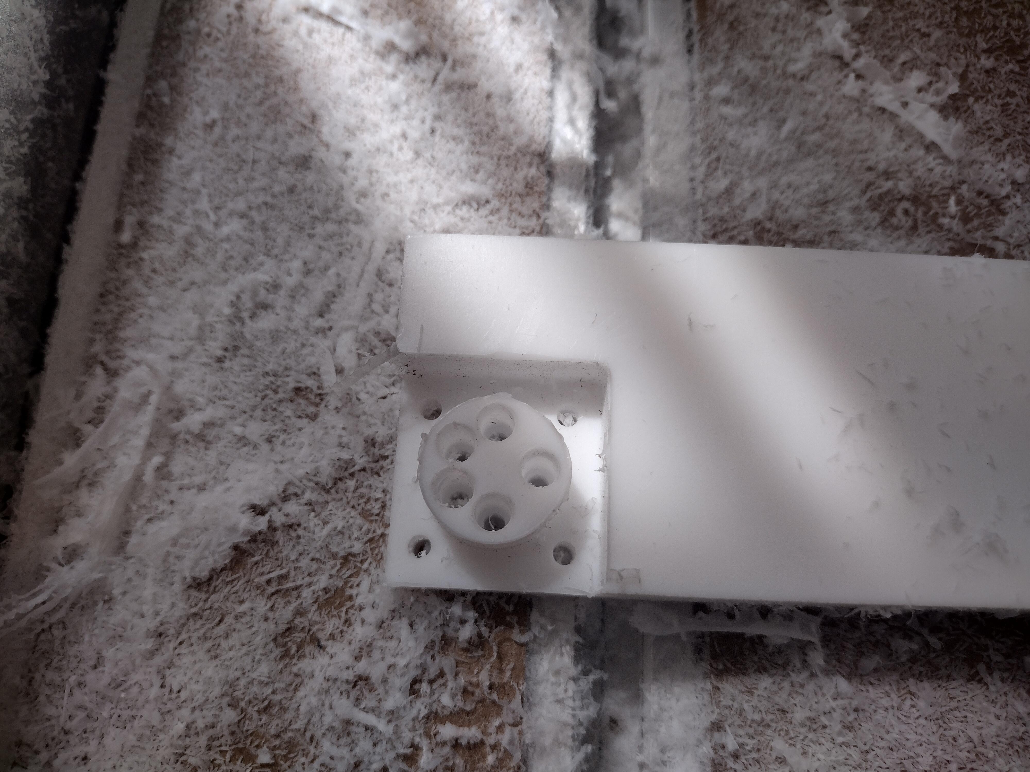
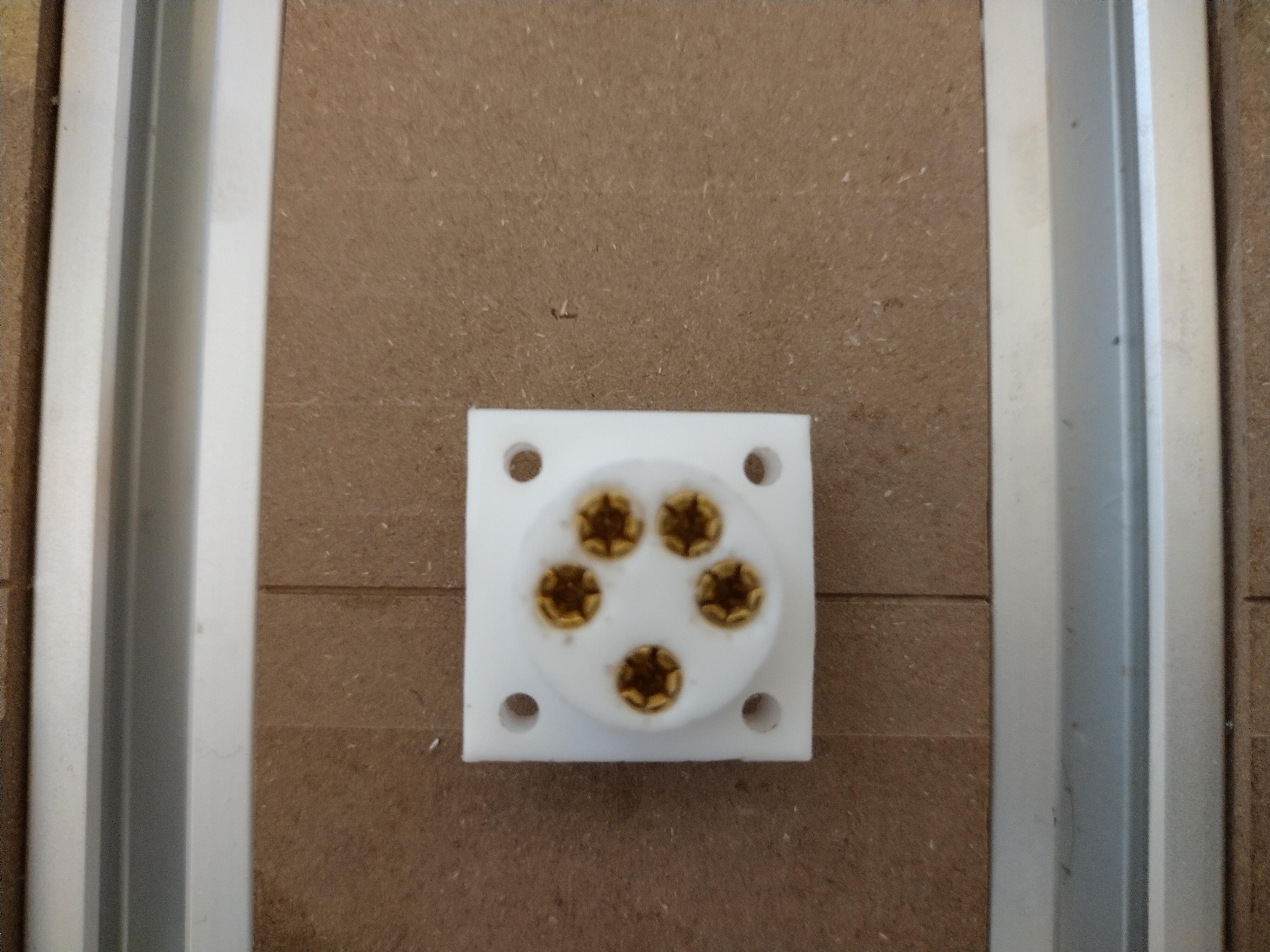
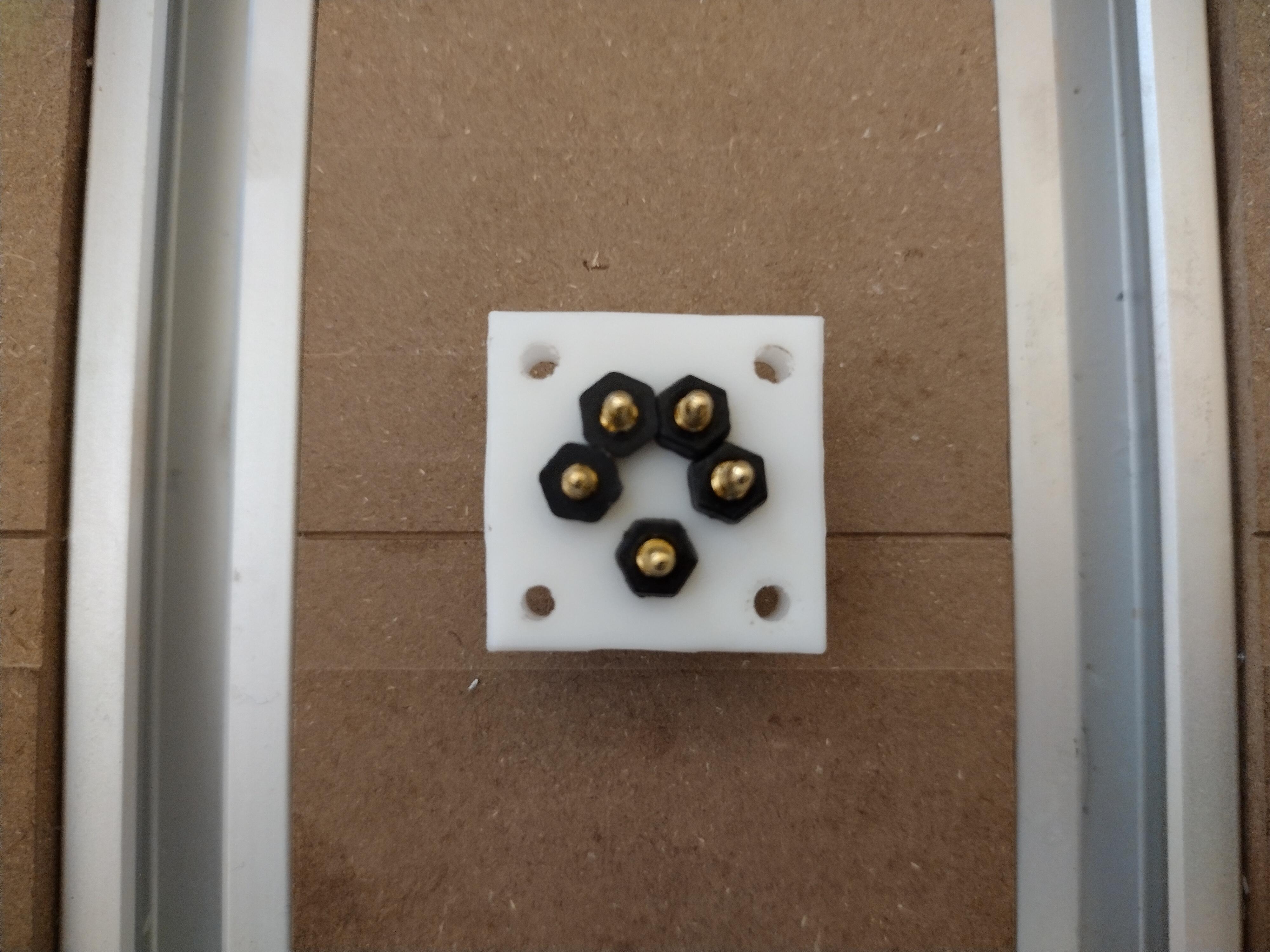
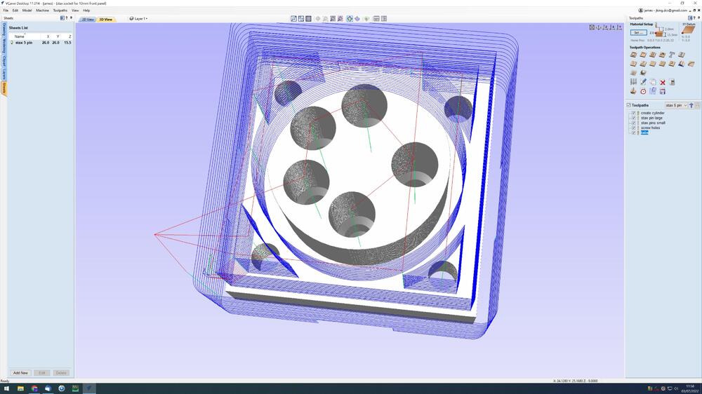
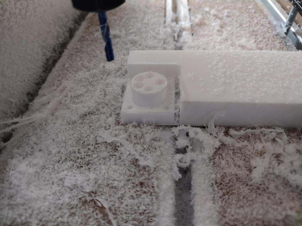
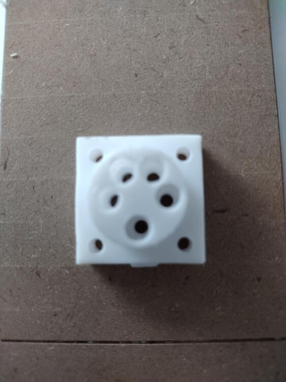
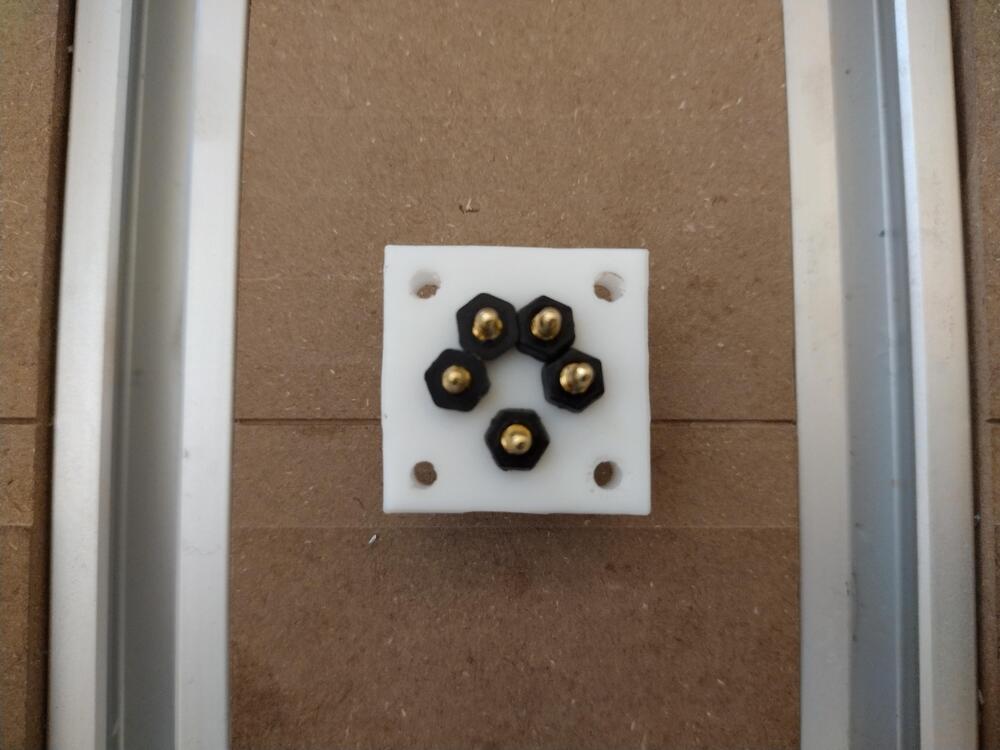
I got bored waiting for the replacement bolts to arrive and so purchased my own and finished installing the missing bolts. Here is my first CNC project: Making my own Stax 5 pin sockets using ptfe design in vectric vcarve desktop: making some (ptfe) chips and no router bits broken... final result after deburring and running the drill holes all the way through: overall I am happy with the result. The tabs holding the piece into the material could have been smaller and after test fitting the pins the holes should have been 4.6mm rather than 4.5mm but I don't have a 4.6mm drill yet. other than that I have a working Stax socket 🙂 This first version uses 3 tools: 3.175mm end mill, 3mm drill and 4.5mm drill.... its slow and boring changing tools, so I remade the tool paths only using a 3.175mm end mill, ran the code and found the drill holes were smaller than expected. I measured the 3.175mm end mill... 3.13mm... hmm... so I updated the tool data base with the correct diameter and re-ran the cut again.... I realise now I have to measure all my tools and not rely on the size they claim. I could not find any metal m3 nuts that fit the threads but are small enough not to touch each other so I used nylon nuts instead. I tested the insulation between the closest pins pairs to each other and got 300Gohm at 5.5Kv.

-
on further inspection the clamps held the work down ok, but the table is bowed downwards in the middle, hence the vibrations in mid way. I will experiment with the tape and ca glue. I also have purchased a thick spoil board which I will attach very firmly to the bed and level that. But I don't see much point in doing the levelling until I have put in the missing bolts which I cant do without some disassembly anyway. I also need to square the Y axis (dual motor) and square the spindle... all the axis come pre assembled - no bolts missing there and I did check all the bolts were tight. almost all the missing bolts are to things like limit switches, drag chain rails, thin guards to stop chips jumping onto the axis threads, bolts for the additional spindle holders etc. I would not run the machine if it did not feel the structural parts were not well bolted together. I could stop all the vibrations by putting weight into the middle of the work piece. The machine (other than the standard spoil board) feels really solid. the laser should arrive in 2 weeks or so. I hope 20W will be powerful enough, but its a free gift from foxalien for the missing bolts and scratches to the controller box.... I don't mind taking things slowly including the speeds and feeds i'm in no hurry - I have a lot of learning to do and a lot of experience to get. I know i'm going to break bits, ruin some work etc.. and im ok with that, hence the cheap bits and working a scrap materials. I was fascinated by wood work and metal work when at secondary school but I ended up studying computer science and university. I like the idea of making things, (I guess it was having lots of lego when I was a child) - and like the idea of making better looking front, top and back panels for my stax amps, so i'm viewing the entire thing as a learning experience a to keep me occupied now I have built all the stax amplifiers I wanted to.
-
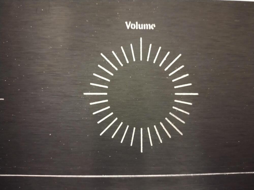
Thank you for the advice and support Kerry, I suspect the chineseium 2mm end mill is the problem.... rather than single flute it has lots of little burs on it and was garbage at clearing chips and sounded like shit at 10mm min cutting speed. I'm hoping single flute will be better. I have some single flute chinesium 3mm end mills and 6mm but I have not been brave enough to try them yet. Once I have got some experience I will get some good quality mills. I tried some engraving with a 30degree 0.2mm chinesium engraving bit and this worked much better no breakages and a lot nicer cutting sounds. I did some rate tests and got up to 160mm 0.022mm depth of cut without breaking anything. I found the line quality slightly degrades as the cutting speed goes up so I settled on 100mm min. I have not tramed the mill yet or made a spoil board or levelled it so I was not expecting perfect results but the engraving is not bad. The lines are a little thick for my liking (I made them 0.4mm wide in the cad) but I managed to cut through the anodizing without an issue at 100mm per min and 0.022mm depth of cut. Part of the e is missing in the volume text, but the text is quite small (which I knew would happen from the cutting simulation. I need a smaller angle engraving tool for the fine detail on the e, so I have ordered some 10degree 0.1mm engraving tools which the simulation shows will fill out the entire e). (sorry its slightly blurry just used my cheap phone could not be bothered to go slr and tripod) For software I tried fusion360 - gui and user experience is diabolical as a lecturer I can get it for free but I hated it. I settled on paying for vcarve desktop - it does what I want, is easy to use - I just wish it had adaptive tool paths. For sender software i'm using candle although I will probably go universal gcode sender. I just tried 3.175mm single flute end mill and got chatter and lots of vibration of the aluminium I was cutting when going above 0.1mm DOC at 250mm/min. I suspect this is because: 1. I have not levelled the supplied spoil board, 2 I only used 4 hold cheap down clamps (material 430mm long, 90mm deep and 10mm thick) and I think painters tape + superglue might be better, 3 my machine is missing half the bolts. (carton containing all the bolts and washers split open in shipping and about half of everything must have fallen out of the box on route) 😞 On the other hand I did not break the tool 🙂 So I'm pausing experimentation until the rest of the bolts and a thicker spoil board arrive, then I can level and make more meaningful experiments...
-
Well I'm no longer a cnc virgin finished building the machine yesterday. Broke my first end mill today. 2mm carbide endmill trying to mill 27mm long ventilation slots in 3mm thick aluminium... first two slots went ok taking tiny nibbles at 0.2mm depth of cut and a feed slow increasing from between 10mm to 100mm per min. Then I got a little too ambitious with the feeds going for 200mm feed and 0.4 and then 0.6mm depth of cut. Instant SNAP I guess this is to be expected.... I did hear the sound of the cutting change a little before hand but did not react in time...Post mortem on the end mill shows it got clogged up... guess I need cutting fluid a single flute end mill and more experimentation... I literally had to use plyers to extract the broken end from the aluminium it got welded in. well just broke a second bit... 100mm feed 0.3 depth of cut is too much for the cheap chinesium 2mm endmill again the end mill bound and clogged up.... need to wait for some (hopefully better) single flute 2mm to arrive....
-
a speed and feed calculator. https://fswizard.com/