

Leaderboard
-
Voltron
High Rollers29Points34512Posts -
Grahame
High Rollers6Points16720Posts -
Craig Sawyers
High Rollers5Points5495Posts -
morphsci
High Rollers5Points13301Posts


Popular Content
Showing content with the highest reputation on 04/27/23 in Posts
-
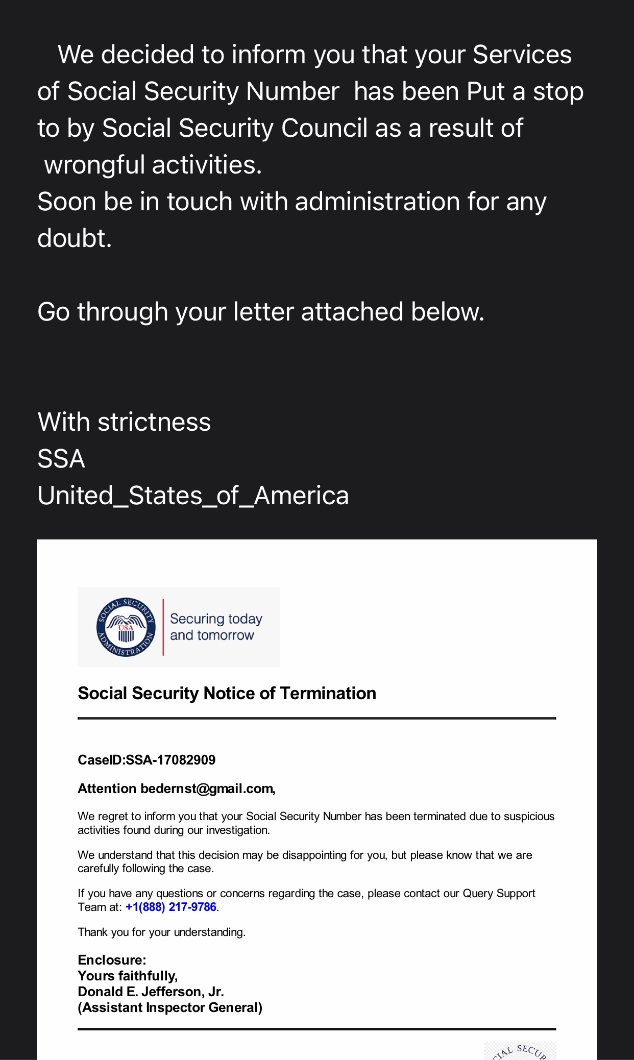
5 pointsOh no! My social security services have been put a stop to! I better soon be touch because the notice was sent with strictness!
 5 points
 -
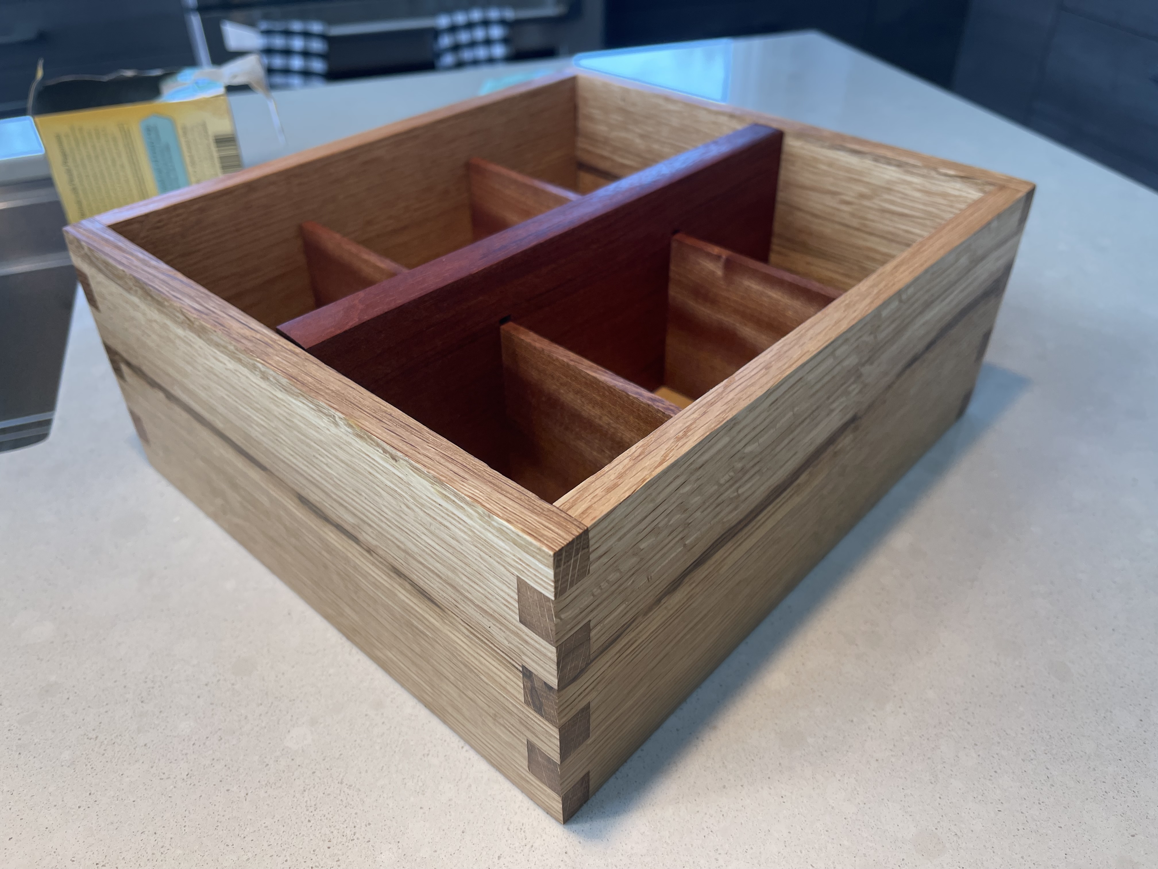
4 pointsThrew together a little quartersawn tea box today with box joints and dado for the bottom all done with the Shaper.
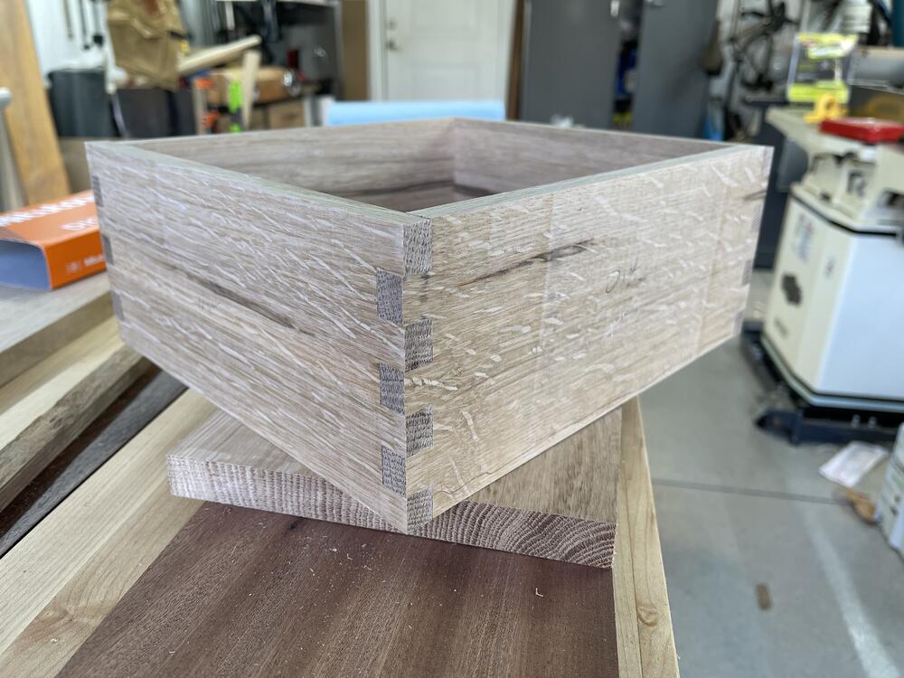
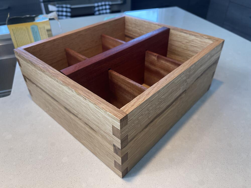
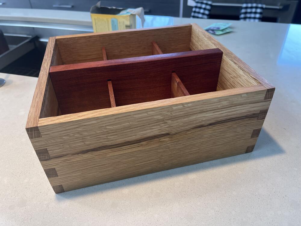 4 points
 -
And this is the story of Abraham Wald and survivorship bias https://medium.com/@penguinpress/an-excerpt-from-how-not-to-be-wrong-by-jordan-ellenberg-664e708cfc3d2 points
-
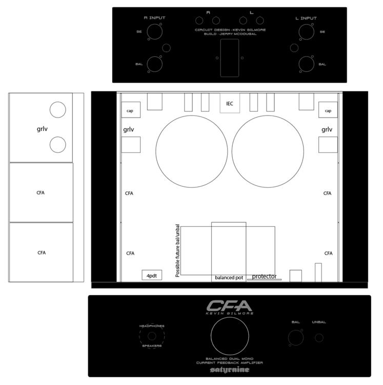
2 pointsI would not stack anything, at least not horizontally. In addition to what John already said, the upper board will always run hotter and also its transistor will be on the upper part of the heatsink already heated up by the lower row of transistors. Stacking boards vertically on the heatsinks is much better, thus the reason for the CFA split boards. Make sure you mount transistors to the lower on the sinks as heat moves from bottom to top.1 pointI would use different layout. Move transformers and grlvs to the front. Move cfa to the rear. Keep DC protection board where it is at the front. Use extension shaft to mount volume pot at the rear close to inputs. Side notes: move ac inlet to the left or right, it doesn't have to be on the center, it gives nothing. Stack the upper cfa higher so that transistors are distributed more evenly over heatsinks area. Move inputs closer to center (and to the pot) and move speaker terminals to outer edge of the chassis. Cause your speakers will be placed to the left and right and maybe quite far away from the amp. Consider stacking transformers on top of each other, you have 120mm clearance if you don't use steel chassis. That way you will have space to mount grlvs horizontally. After all I don't think that amp with bjt output transistors is good to drive speakers. I would consider omitting speaker terminals completely.1 pointhaving the amps boards stacked like that you won't be able to bias the lower board if needed. Just ensure there’s adequate space, maybe longer standoffs.1 point1 point1 pointI use 2SA1413 (It is the same transistor in a different package).1 point1 pointHappy birthday Kevin. Enjoy some: 🎂 You share a birthday with Samuel Morse inventor of the telegraph, Ulysses S. Grant, Sheila Scott (first woman to fly solo around the world) and of course Casey kasem (the voice of Shaggy and Scooby-doo)1 pointYou might want to consider having only balanced inputs and *if* you need to connect a single ended cable to it, then use external Neutrik NA2 MPMF to convert a chinch cable. Will make things simpler. The mount-from-inside version for the 3-pin XLR connectors for the inputs on the back would be the Neutrik NC3FBH2-B or the NC3FBV2-B with vertical pins. For the speaker terminals, personally I would use the Neutrik SpeakOn. Would keep your back plate clean and can be mounted from inside as well into a round hole and are the best speaker wire connectors anyway. NL2MP or NL4MP-ST depending on what kind of connection from the inside you want and bi-wiring (4-pole) or not. This will clean up your back panel with only 2 holes on the left and 2 on the right side. In the middle you can have the IEC inlet. Just a thought...1 pointThat was very cool (sampled through it but will watch in full later)! Loved that they did Swamp Thing by The Chameleons!1 pointAlmost ready to start building my CFA2/3! Dual Mono, 2x GRLV, 4x CFA2 boards, and maybe a bal/unbal down the road. I plan to use this with my LCD-2's (orig), and my desk monitors via added speaker outs. I have all the components on hand but the chassis so far. Details: Dissipante 3U chassis. Mounting boards directly to heatsink. 2x Antek 100VA 30V trafos with steel covers MUR820 Ultra Fast diodes on daughterboards vs standard GBU4 package rectifiers for GRLV boards Goldpoint quad/balanced stepped attenuator KG Headphone Protector Board (just had a set made at Oshpark) Options for Bal and SE in Bal and Unbal outs (unbal out only works with se ins in CFA2 mode obv) Dale RN60 resistors throughout, Used Pars's BOM Here's what I have drawn up so far for Front/Rear panels I'm having made at Modushop, as well as internal layout plan thus far. Getting panels engraved/machined, with the "CFA" cut deeply at a bevel. Large circle where vol knob is is just a placeholder for the largest possible size knob. Dotted line around headphone/speaker switch is a rear recess since front panel is 10mm thick. Many Thanks to the infamous Dukei/Miroslav and Pars for guidance, as well as arteom from diyaudio for generously supplying boards, and of course the man himself for this awesome design.
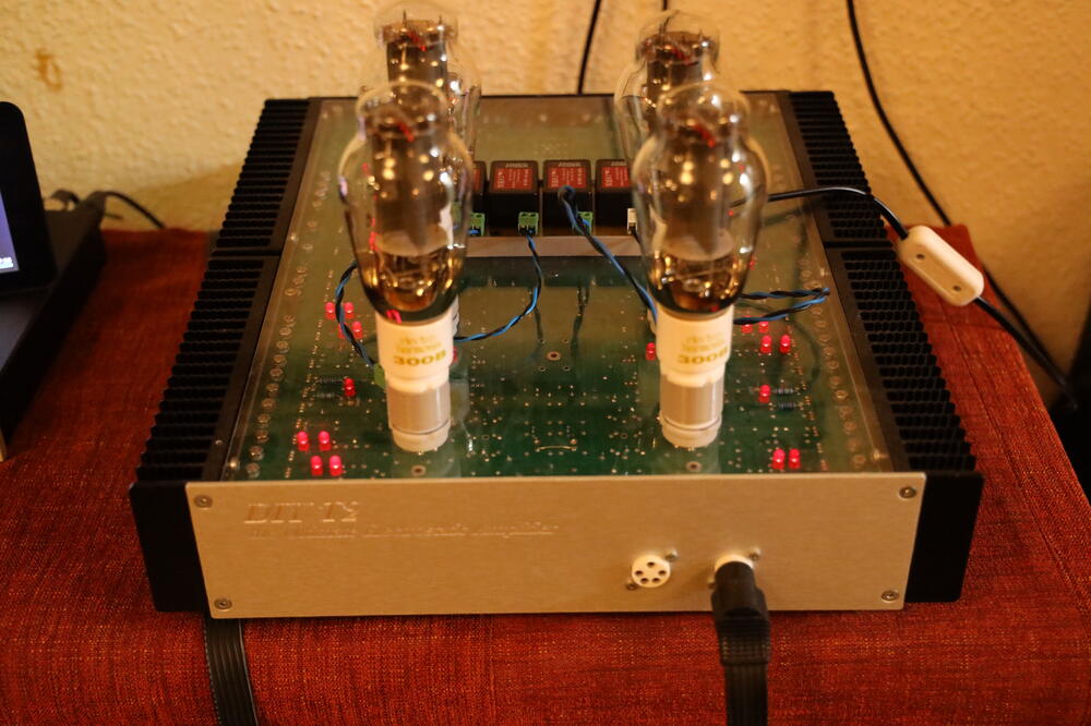
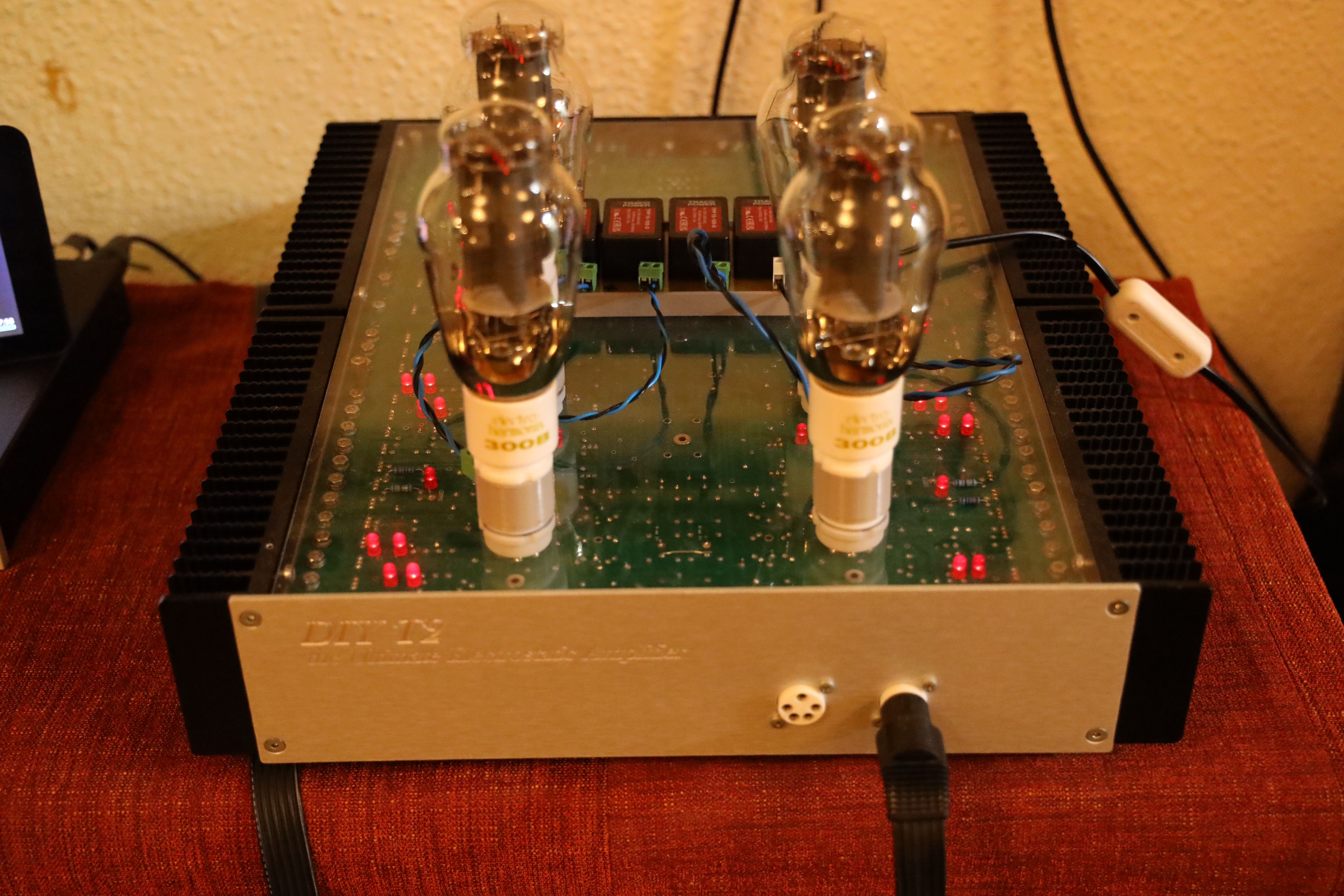
 1 point1 pointDIY T2 amplifier with 300B tubes. Amplifier is built on Kevin’s board. Only modification is decreased high voltages, +/-400V instead of +/-500V. Homemade 300B to EL34 adapters connected to four Traco 5V switched PS for filament power. I only replaced the EL34 with 300B along with the filament power supply. No other adjustments. It works – I’m in no harry to change back to EL34.
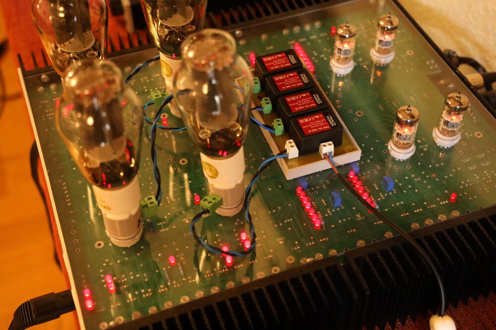
 1 point0 pointsLaser surgery left eye to reduce pressure. This is my third time for my glaucoma but it has been almost 6 years since the last one. Right eye to be done middle of May.0 points0 pointsRIP Jerry Springer. BBC News - Jerry Springer: Era-defining TV host dies aged 79 https://www.bbc.co.uk/news/entertainment-arts-65415348 Without whom we would not have https://en.m.wikipedia.org/wiki/Jerry_Springer:_The_Opera0 points


Important Information
By using this site, you agree to our Terms of Use.